RIDGID CM1450 User manual

• Français – 13
• Castellano – pág. 27
WARNING!
Read this Operator’s Manual
carefully before using this tool.
Failure to understand and fol-
low the contents of this manu-
al may result in electrical
shock, fire and/or serious per-
sonal injury.
14″Abrasive
Cut-Off Machine
OPERATOR’S
MANUAL
CM1450

Ridge Tool Companyii
CM1450 14″Abrasive Cut-Off Machine
Table of Contents
Recording Form for Machine Serial Number..............................................................................................................1
General Safety Information
Work Area Safety........................................................................................................................................................2
Electrical Safety..........................................................................................................................................................2
Personal Safety ..........................................................................................................................................................2
Tool Use and Care......................................................................................................................................................3
Service........................................................................................................................................................................3
Specific Safety Information
Machine Safety ..........................................................................................................................................................3
Description, Specifications and Standard Equipment
Description..................................................................................................................................................................4
Specifications..............................................................................................................................................................4
Standard Equipment ..................................................................................................................................................5
Accessories ................................................................................................................................................................5
Machine Assembly
Removing The Abrasive Cut-Off Wheel......................................................................................................................5
Installing The Abrasive Cut-Off Wheel........................................................................................................................5
Down Stop Adjustment ..............................................................................................................................................6
Inspect Cut-Off Machine ..............................................................................................................................................6
Machine and Work Area Set-Up ..................................................................................................................................7
Operating Abrasive Cut-Off Machine
Clamping Workpiece ..................................................................................................................................................8
Inspecting Workpiece..................................................................................................................................................8
Cutting With Abrasive Cut-Off Machine......................................................................................................................9
Removing The Workpiece ..........................................................................................................................................9
Tips For Using Abrasive Cut-Off Machine ..................................................................................................................9
Transporting The Cut-Off Machine ............................................................................................................................9
Maintenance Instructions
Replacing Carbon Brushes ......................................................................................................................................10
Lubrication ................................................................................................................................................................10
Machine Storage..........................................................................................................................................................10
Service and Repair......................................................................................................................................................10
Troubleshooting Guide..........................................................................................................................................11-12
Wiring Diagram............................................................................................................................................................12
Lifetime Warranty ........................................................................................................................................Back Cover

CM1450
14″Abrasive Cut-Off Machine
CM1450 14″Abrasive Cut-Off Machine
Record Serial Number below and retain product serial number which is located on nameplate.
Serial No.

Ridge Tool Company2
CM1450 14″Abrasive Cut-Off Machine
General Safety Information
WARNING! Read and understand all instructions. Failure
to follow all instructions listed below may
result in electric shock, fire, and/or serious
personal injury.
SAVE THESE INSTRUCTIONS!
Work Area Safety
•Keep your work area clean and well lit. Cluttered
benches and dark areas invite accidents.
•Do not operate tools in explosive atmospheres,
such as in the presence of flammable liquids,
gases, or dust. Tools create sparks which may ignite
the dust or fumes.
•Keep by-standers, children, and visitors away
while operating a tool. Distractions can cause you to
lose control.
•Protect others in the area from debris such as
sparks and chips. Provide barriers or shields as
required.
Electrical Safety
•Grounded tools must be plugged into an outlet,
properly installed and grounded in accordance
with all codes and ordinances. Never remove the
grounding prong or modify the plug in any way. Do
not use any adapter plugs. Check with a quali-
fied electrician if you are in doubt as to whether the
outlet is properly grounded. If the tools should elec-
trically malfunction or break down, grounding pro-
vides a low resistance path to carry electricity away
from the user.
•Avoid body contact with grounded surfaces. There
is an increased risk of electrical shock if your body is
grounded.
•Do not expose electrical tools to rain or wet con-
ditions. Water entering a tool will increase the risk of
electrical shock.
•Do not abuse cord. Never use the cord to pull the
plug from an outlet. Keep cord away from heat, oil,
sharp edges or moving parts. Replace damaged
cords immediately. Damaged cords increase the risk
of electrical shock.
•When operating a tool outside, use an outdoor
extension cord marked “W-A” or “W”. These cords
are rated for outdoor use and reduce the risk of elec-
trical shock.
•Use only three-wire extension cords which have
three-prong grounding plugs and three-pole recep-
tacles which accept the tool’s plug. Use of other
extension cords will not ground the tool and increase
the risk of electrical shock.
•Use proper extension cords. (See chart.) Insuf-
ficient conductor size will cause excessive voltage
drop and loss of power.
Personal Safety
•Stay alert, watch what you are doing and use
common sense when operating a power tool. Do
not use tool while tired or under the influence of
drugs, alcohol, or medications. A moment of inat-
tention while operating power tools may result in seri-
ous personal injury.
•Dress properly. Do not wear loose clothing or jew-
elry. Contain long hair. Keep your hair, clothing,
and gloves away from moving parts. Loose clothes,
jewelry, or long hair can be caught in moving parts.
•Avoid accidental starting. Be sure switch is OFF
before plugging in. Plugging in tools that have the
switch ON invites accidents.
•Remove adjusting keys before turning the tool
ON. A wrench or a key that is left attached to a rotating
part of the tool may result in personal injury.
•Do not over-reach. Keep proper footing and bal-
ance at all times. Proper footing and balance enables
better control of the tool in unexpected situations.
•Use safety equipment. Always wear eye protec-
tion. Dust mask, non-skid safety shoes, hard hat, or
hearing protection must be used for appropriate con-
ditions.
Grounding prong
Cover of
grounded
outlet box
Grounding prong
Minimum Wire Gauge for Extension Cord
Nameplate
Amps Total Length (in feet)
0 – 25 26 – 50 51 – 100
0 – 6 18 AWG 16 AWG 16 AWG
6 – 10 18 AWG 16 AWG 14 AWG
10 – 12 16 AWG 16 AWG 14 AWG
12 – 16 14 AWG 12 AWG NOT RECOMMENDED

Ridge Tool Company 3
CM1450 14″Abrasive Cut-Off Machine
Some dust created by power sanding,
sawing, grinding, drilling and other construction activi-
ties contains chemicals known to the State of California to
cause cancer, birth defects or other reproductive harm.
Some examples of these chemicals are:
•lead from lead-based paints
•crystalline silica from bricks and cement and other
masonry products
•arsenic and chromium from chemically-treated lumber
Your risk from these exposures varies, depending on
how often you do this type of work. To reduce your expo-
sure to these chemicals: work in a well ventilated area and
work with approved safety equipment such as those dust
masks that are specially designed to filter out micro-
scopic particles.
•Never stand on tool or its stand. Serious injury could
occur if the tool is tipped or if the cutting tool is acci-
dentally contacted. Do not store materials on or near the
tool such that it is necessary to stand on the tool or its
stand to reach them.
•Keep guards in place, in working order, and in proper
adjustment and alignment.
Tool Use and Care
•Use clamps or other practical way to secure and
support the workpiece to a stable platform. Holding
the workpiece by hand is unstable and may lead to
loss of control.
•Do not force tool. Use the correct tool for your ap-
plication. The correct tool will do the job better and
safer at the rate for which it is designed.
•Do not use if switch does not turn it ON or OFF.
Any tool that cannot be controlled with the switch is
dangerous and must be repaired.
•Disconnect the plug from the power source before
making any adjustments, changing accessories or
storing the tool. Such preventive safety measures
reduce the risk of starting the tool accidentally.
•Store idle tools out of the reach of children and
other untrained persons. Tools are dangerous in
the hands of untrained users.
•Never leave tool running unattended. Turn power
OFF. Do not leave tool until it comes to a complete
stop.
•Check for misalignment or binding of moving
parts, breakage of parts and any other condition
that may affect the tool’s operation. If damaged,
have the tool serviced before using. Many accidents
are caused by poorly maintained tools.
•Use only accessories that are recommended by
the manufacturer for your model. Accessories that
may be suitable for one tool may become hazardous
when used on another tool.
•Inspect tool and extension cords periodically and
replace if damaged. Damaged cords increase the
risk of electrical shock.
•Keep handles dry and clean; free from oil and
grease. Allows for better control of the tool.
Service
•Tool service must be performed only by qualified
repair personnel. Service or maintenance performed
by unqualified repair personnel could result in injury.
•When servicing a tool, use only identical replace-
ment parts. Follow instructions in the Maintenance
Section of this manual. Use of unauthorized parts or
failure to follow maintenance instructions may create a
risk of electrical shock or injury.
Specific Safety Information
WARNING
Read this operator’s manual carefully before using
the CM1450. Failure to understand and follow the
contents of this manual may result in electrical
shock, fire and/or serious personal injury.
Call the Ridge Tool Company, Technical Service Depart-
ment at (800) 519-3456 if you have any questions.
Machine Safety
•Wear proper apparel while using an abrasive cut-
off machine. Safety goggles or safety glasses with
side shields that are in compliance with ANSI or CSA
standards, dusk mask, ear protection, leather gloves
and a shop apron capable of stopping small wheel or
workpiece fragments.
•Only use a 14 inch abrasive wheel rated for use at
3900 RPM. Do not use larger wheels or worn down
damaged wheels from larger cut off machines.
Wheels running over their rated speed can fly apart
and possibly striking you or a bystander. Wheels
intended for larger tools are not suitable for the higher
speed of the smaller tool.
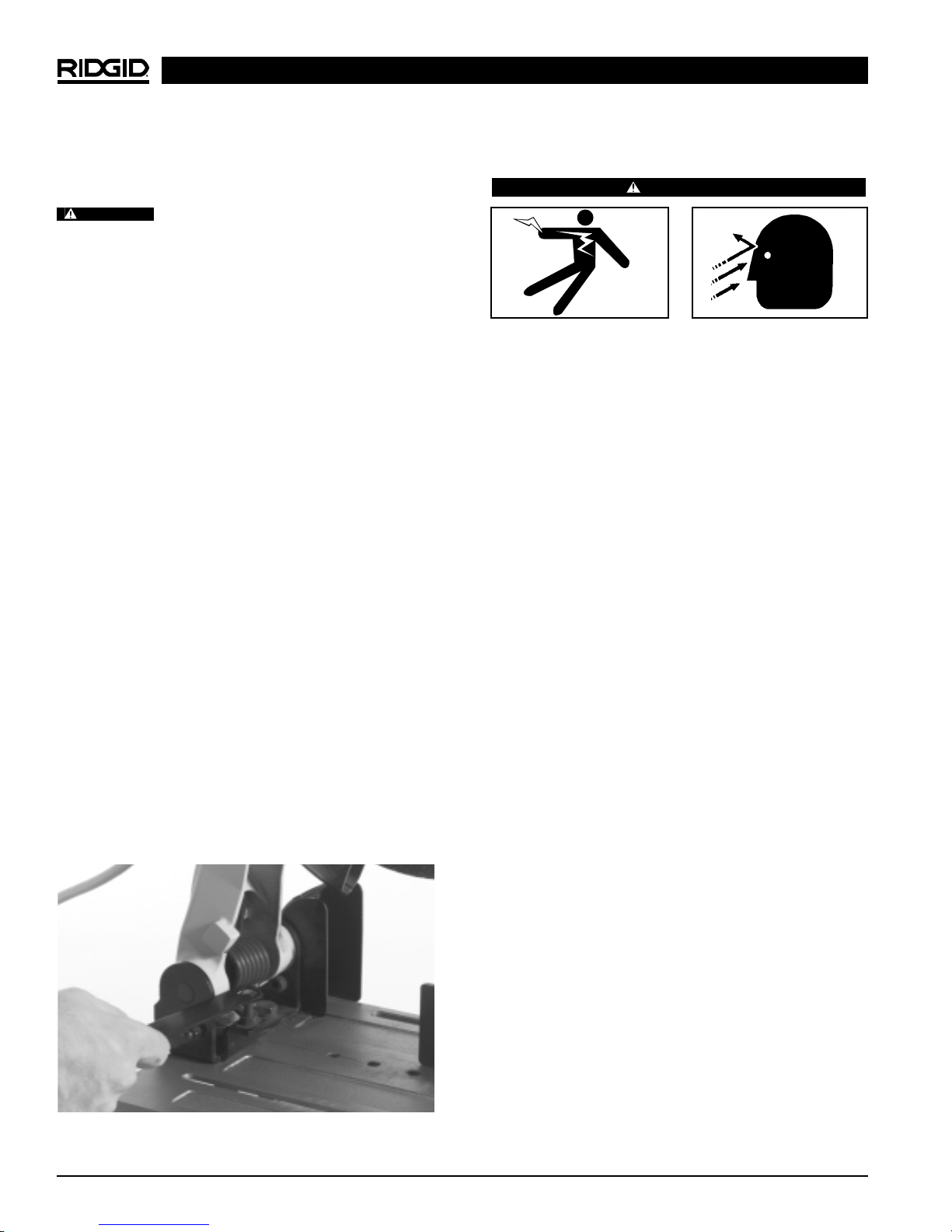
•Keep hands away from the cutting area and the
wheel. Never place your hand behind the wheel. Do
not attempt to remove or clamp material when
the wheel is moving. Contact with the spinning wheel
may cause serious injury.
WARNING

•Do not use any type of cutting lubricant with this
cut-off tool. Lubricant may enter motor resulting in an
increased risk of electrical shock.
•Do not cut or attempt to cut masonry, stone or
ceramic. The fine dust created when cutting will dam-
age the motor.
Description, Specifications and
Standard Equipment
Description
The RIDGID CM1450 Abrasive Cut-Off Machine is
designed to cut ferrous and non-ferrous material such as
the following:
•Gas pipe, electrical pipe and conduit.
•Steel and aluminum angle, channel and bar
A quick lock release vice clamps the workpiece and
allows an angle cut from 45°to 90°. The motor oper-
ates with 115 volt, single phase, 60 Hz, AC current.
Specifications
NOTE! Maximum width capacity is approximately 81/4″
at 90°and 5″at 45°.
Use of tool for cutting larger than recom-
mended shapes may lead to motor burn-out and possible
electrical shock.
Motor
Type ..............................Universal
Volts ..............................115AC, 60Hz
Amps.............................15
No Load Speed .............3900 RPM
Rotation Of Shaft...........Counterclockwise
Blade Size.....................14″Diameter with 1″Arbor
Hole
Weight ...........................54 lbs. (24 kgs.)
•Keep the lower wheel guard attached and working
properly. Keep your body position to either side of
the wheel, but not in line with the wheel. Is important
to position your body and the guard to minimize body
exposure from the possible fragments of a burst wheel.
•Do not grind against the side of these abrasive cut-
off wheels. Do not allow the wheel to twist or bind.
Side forces applied to these wheels may cause them
to shatter.
•Before each use inspect the cut-off wheel for
chips and cracks. Do not use a wheel that may be
damaged. When installing a new wheel carefully
handle individual cut-off wheels to avoid chip-
ping or cracking. Run the tool at no load for one
minute, holding the tool’s cutting head down and
in the direction away from people. Wheels with
flaws will normally break apart during this time.
Fragments from a wheel that bursts during operation
may strike you or bystanders.
•Do not “jam” the abrasive wheel into the work or
apply excessive pressure while using this ma-
chine. Avoid bouncing and snagging the wheel,
especially when working corners and sharp edges.
If the wheel is damaged due to misuse it may develop
cracks and eventually burst or shatter without warning.
•Always use the vice to clamp the work and prop-
erly support the over-hanging portion of the work-
piece level with the base of the machine. Proper
support of workpiece is important to keep the cut-off
and overhanging pieces from falling.
•Do not use this tool with “wood carving” blade or
standard wood cutting toothed blades. These
blades are not intended for this machine and can cre-
ate loss of control during use.
•This tool and abrasive wheel are not intended to
cut wood or wood products. Abrasive wheels cut by
grinding or fretting while in workpiece with the embed-
ded grit in the wheel. These grits may grab wood and
cause loss of control or could cause the wood to burn
due to friction heating.
•Do not set or mount the tool on a flammable sur-
face or use the abrasive cut-off machine near
flammable materials. During operation the wheel
ejects sparks and hot chips from grinding on the work-
piece. These sparks could ignite flammable materials.
•Never cut or attempt to cut magnesium with this
tool. The dust generated when cutting magnesium is
highly flammable and may be explosive under certain
conditions.
CM1450 14″Abrasive Cut-Off Machine
Ridge Tool Company4
WARNING
Applicable Wheel 355mm (14″) Outer Diameter x Less Than 4.5mm (3/16″)
Dimensions Thickness x 25.4mm (1″) Hole Diameter
Workpiece
Configuration
(Cross-Section)
Maximum 1/2″2″5″41/2″1/2″5″
Cutting Capacity (12.7mm) (50.8mm) (127mm) (114.3mm) (12.7mm) (127mm)
“a” Square or 1/2″wall 1/2″wall Solid
Round (12.7mm) (12.7mm)
thickness thickness

Ridge Tool Company
Standard Equipment
•CM1450 Abrasive Cut-Off Machine
•14″Abrasive Wheel (Installed)
•Arbor Wrench (Stored Under Base)
Accessories
Catalog No. Description
85232 14″Abrasive Wheel
96312 Arbor Wrench
Figure 1 – CM1450 14″Abrasive Cut-Off Machine
Machine Assembly
WARNING
Make sure machine is unplugged from power
source before installing a cut-off wheel or making
any adjustment to the machine.
Removing The Abrasive Cut-Off Wheel
1. Remove the arbor wrench located under the base of
the machine.
2. Lift the lower guard up and tilt the lower guard assem-
bly back so the arbor screw is exposed (Figure 2).
5
CM1450 14″Abrasive Cut-Off Machine
Figure 2 – Removing Cut-Off Wheel
3. Locate the lock pin under the handle. Press the lock
pin and hold in while turning the arbor wrench
counter-clockwise (Figure 2). The arbor will engage
after some turning of the wrench.
NOTE! The arbor screw has a right hand thread. This
helps prevent unwanted loosening of the arbor
screw during normal operation.
4. Remove the arbor screw, lock washer, arbor washer
and outer flange.
NOTE! Pay attention to pieces removed, noting their
position and direction they face (Figure 3). Wipe
the inner and outer flanges clean of any debris
before installing new cut-off wheel.
Figure 3 – Position Of Arbor Screw, Arbor Washer and
Outer Flange
Installing The Abrasive Cut-Off Wheel
WARNING
To reduce the risk of injury from a thrown work-
piece, use a 14″diameter abrasive cut-off wheel
that is rated for 3900 RPM.
NOTE! Choose the right 14″diameter cut-off wheel for
the material and the type of cutting you plan to
do. For example, when cutting steel, use abra-
sive cut-off wheel especially designed to be
used on steel.
Carrying
Handle
Upper Guard
Handle
ON/OFF
Trigger
Switch
Lock Pin
Lower Guard
Downstop
Arbor
Wrench Stationary
Vise Chain
Arbor Lock
Arbor Screw
Arbor Screw
Outer Flange
Abrasive Wheel

1. Inspect the cut-off wheel to ensure it is not warped or
cracked. Make sure that all wheel flanges and other
mounting hardware are in good condition.
Cutting with a damaged wheel is hazard-
ous. Do not use a wheel that has been dropped or shows
any damage.
2. Install the new 14″wheel.
3. Install the outer flange, washer, lock washer and
arbor screw (Figure 3). Press the lock pin and turn the
arbor wrench clockwise to secure the wheel. Tighten
arbor screw securely, but do not overtighten. Over-
tightening the bolt may damage the wheel or flanges.
4. Depress the lower guard. Make sure the lock pin is
released so the wheel turns freely and the flanges are
properly arranged.
NOTE! The arbor lock can be damaged by improper
use. If the arbor lock does not hold, lower the
wheel down on a scrap of wood positioned
against the fence. This will serve as an alter-
nate locking means.
5. Lower the wheel into the table slot and check for
any contact with the base or the surface which tool is
mounted on. If the cut-off wheel contacts the base,
the downstop must be adjusted.
Down Stop Adjustment
NOTE! The downstop should be adjusted so that the
maximum cutting capacity is maintained.
1. Lower cutter head until the arm hits the downstop.
2. Turn wheel by hand to verify maximum cutting capac-
ity. The cut-off wheel must not contact any part of the
base.
3. If contact occurs, adjust downstop screw and jam nut
until problem is corrected (Figure 4).
Figure 4 – Adjusting Downstop Screw For Optimum
Cut-Off Wheel Height
Inspect Cut-Off Machine
WARNING
To prevent serious injury, inspect your Cut-Off
Machine on a regular basis. The following inspec-
tion procedures should be performed before each
use of the tool:
1. Inspect the power cord and plug for damage. If the
grounding prong is missing or the cord is damaged,
do not use the tool until the cord has been replaced.
2. Make sure the switch turns the tool ON and OFF. If
broken, do not use until it is replaced.
3. Inspect the machine for any broken, missing, mis-
aligned or binding parts as well as any conditions
which may affect the safe and normal operation of the
tool. If any of these conditions are present, do not use
the tool until the problem has been repaired. Do not
use damaged blades.
4. Make sure all guards are in place and in working
order.
NOTE! To check the operation of the lower guard, push
the arm all the way down, then let it rise up until
it stops by itself. The lower guard should now be
in the fully closed position. If not, follow the
instructions in the Troubleshooting section of
this manual. Do not use the saw until the guard
has been fixed.
5. Clean any oil, grease or dirt from the handles. This
reduces the risk of injury due to the tool slipping
from your grip.
6. Use only accessories recommended for your tool.
Accessories used for other tools may be hazardous
when used on this saw and lead to serious injury.
7. Make sure cut-off wheel is properly aligned with the
power head all the way down. Hand spin the cut-off
wheel and check for clearance. If the abrasive wheel
hits anything, make necessary adjustments to the
downstop.
8. Inspect the abrasive wheel for damage or wear. If
necessary, replace prior to using. Worn or damaged
wheel can lead to injury, tool breakage or excessive
heat build-up in the workpiece and the tool. Check
that the speed rating of the wheel is at least 3900
CM1450 14″Abrasive Cut-Off Machine
Ridge Tool Company6
WARNING

Ridge Tool Company 7
CM1450 14″Abrasive Cut-Off Machine
selected earlier. If the power cord does not reach the
outlet, use an extension cord in good condition.
To avoid electrical shock and electrical
fires, never use an extension cord that is damaged or
does not meet the following requirements:
•The cord has a three-prong plug similar to shown in
Electrical Safety section.
•The cord is rated as “W”or “W-A”if being used out-
doors.
•The cord has sufficient wire thickness (14 AWG below
25′/12 AWG 25′- 50′). If the wire thickness is too
small, the cord may overheat, melting the cord’s insu-
lation or causing nearby objects to ignite.
To reduce risk of electrical shock, keep all
electrical connections dry and off the ground. Do not
touch plug with wet hands. Make sure power cord is
clear of abrasive wheel.
NOTE! Use of extension cords over 50 ft is not recom-
mended. An improper extension cord will result
in deterioration of the performance of the cut-off
machine.
6. Check the unit to insure it is operating properly.
•To start the tool, firmly grasp the handle then depress
trigger switch (Figure 5). Keep your body positioned to
either side of the wheel but not in line with the wheel.
•Depress and hold the switch for one full minute. Inspect
the moving parts for misalignment, binding, odd noises
or any other unusual conditions that may affect the
safe and normal operation of the machine. If such con-
ditions are present, have the machine serviced.
•If abrasive wheel wobbles or vibrates discard and
replace immediately.
Wheels with flaws may break apart caus-
ing serious injury to you or bystanders.
•Release the trigger switch.
Figure 5 – ON/OFF Trigger Switch
RPM and is the right 14″diameter wheel for the
material and type of cutting you plan to do.
Do not use this tool with wood carving
blade or standard wood cutting tool blades.
Machine and Work Area Set-Up
WARNING
To prevent serious injury, proper set-up of the
machine and work area is required. The following
procedures should be following to set-up the abra-
sive cut-off machine:
Work Area
1. Locate a work area that has the following:
•Adequate lighting
•No flammable liquids, vapors or dust that may ignite.
•Grounded 15 amp electrical outlet.
•Clear path to the electrical outlet that does not
contain any sources of heat or oil, sharp edges or
moving parts that may damage the electrical cord.
•Dry place for machine and operator. Do not use
the machine while standing in water.
•Level ground where there is plenty of room for
handling and supporting workpiece.
Do not set or mount tool on a flammable
surface or use the abrasive cut-off machine near flam-
mable materials. Sparks and hot chips from grinding of the
workpiece could ignite flammable materials.
2. Clean up the work area prior to setting up any equip-
ment. To prevent slips and falls, always wipe up any
oil that may be present.
3. Place the machine on a flat, level table. Secure the
tool to its support if it tends to slip, walk, or slide during
use.
Failure to place the machine on a stable
surface may result in tipping and serious injury.
4. If workpiece extends beyond the table, use one or
more supports.
Failure to properly support the workpiece
can result in the unit tipping or the workpiece falling.
5. Plug the machine into the electrical outlet making
sure to position the power cord along the clear path
WARNING
WARNING
WARNING
WARNING
WARNING
WARNING
ON/OFF
Trigger Switch
WARNING

Ridge Tool Company8
CM1450 14″Abrasive Cut-Off Machine
Operating Abrasive Cut-Off
Machine
WARNING
Wear safety goggles, leather gloves, dust mask
and ear protection. Make sure guards are in place
and in working order.
Always clamp the workpiece with the vise. Do
not perform any operation freehand.
Keeps hands out of the path of abrasive wheel
Never reach around or in back of the wheel. Do not
attempt to remove or clamp material when wheel
is moving.
Clamping Workpiece
Always use the vice to hold the workpiece in place on the
cut-off machine table. The stationery vice moves back-
ward and forward and adjusts to any angle between 90 to
45 to the left or right (Figure 6). The maximum width
capacity is approximately 81/4″at 90 and 5″at 45.
When making cuts, the centerline of the wheel should con-
tact approximately the midpoint of the workpiece and it
should be midway between the stationary vice and the
adjustable vise plate.
1. To adjust the stationary vise, remove the vise adjust-
ment bolt. Loosen the miter lock handle and reposition
the stationary vice in one of the other two hole loca-
tions (Figure 6).
Replace and tighten the vise adjustment bolt.
Figure 6 – Stationary Vise Adjustment
2. To change the cutting angle, loosen the miter lock
handle by pushing down and rotating counterclock-
wise (Figure 7).
Reposition the vise at the desired angle and tighten
the miter lock handle.
Figure 7 – Cutting Angle Adjustment
3. Raise the quick release lever to disengage it from
the threads (Figure 6). Adjust the position of the
vise plate depending on the workpiece size. Place
the workpiece into the vise. If it extends beyond
the base, provide proper supports.
4. Lower the quick release lever to engage screw thread
and lock the vise. Turn vice handle clockwise to clamp
workpiece.
5. Position work in vise so that if jam occurs, the wheel
will not tend to move the workpiece in the vise. Clamp
it securely.
6. Clamp the material correctly in center relative to the
blade. Angles should be in an inverted position.
Generally, the cut-off machine will cut most efficient-
ly if the wheel is cutting the thinnest section at one
time (Figure 8).
Figure 8 – Clamping The Workpiece
Inspecting Workpiece
Consider the following when planning the
way you hold the workpiece from start to finish.
Planning your work reduces the risk of thrown pieces
caused when the workpiece binds on the cut off wheel and
is torn from your hands.
•Always clamp workpiece using the vice to hold the
work.
•Clamp your workpiece solidly against the fence and
tabletop so will not rock or twist during the cut.
•Make sure there are no debris between the workpiece
and its supports.
•Make sure no gaps between the workpiece, fence and
table will let the workpiece shift after it is cut in two.
Vise Adjustment Bolt
Miter Lock Handle
Vise Adjustment Bolt
Base
Miter Lock Handle
Screw Shaft
Stationary Vise Release
Lever WARNING
Adjustable
Vise Plate

•Keep the cut-off piece free to move sideways after it is
cut off. Otherwise, it could get wedged against the cut-
off wheel and could be thrown violently.
•Clear everything except the workpiece and related
support devices off the table before turning the machine
on.
Use extra caution with large, very small or
awkward workpieces:
•Use extra supports (tables, sawhorses, blocks, etc.) for
any workpieces large enough to tip when not held
down to the tabletop.
•Never use another person as a substitute for a table
extension, or as additional support for a workpiece
that is longer or wider than the basic cut-off machine
table or to help feed, support or pull the workpiece.
•Do not use this tool to cut pieces too small to let you
easily hold the work with the vise.
•When cutting irregularly shaped workpieces, plan your
work so it will not slip, pinch the cut-off wheel and be
torn from the vise.
Cutting With Abrasive Cut-Off Machine
WARNING
Never cut wood, magnesium, masonry, stone or
ceramic with this tool.
Keep your face and body to one side of the abra-
sive wheel, out of line with possible thrown sparks
or dust.
Do not use any type of cutting lubricant with this
cut-off tool.
1. To start tool, firmly grasp the handle and depress the
trigger switch. Be sure to allow the motor to reach
maximum speed prior to cutting. This will help reduce
the risk of thrown workpieces.
2. When beginning a cut with the tool, care should be
exercised not to bump or slam the wheel into the
work. Once it has entered the workpiece, continue to
cut with an even smooth stroke. Do not apply exces-
sive pressure.
If the wheel is damaged do to misuse, it
may develop cracks and eventually shatter without warn-
ing.
NOTE! The faster a cut is made the less heat is creat-
ed in the workpiece, preventing discoloring,
and wheel life is prolonged. Cut with a steady
force without overloading the machine.
3. When the cut is complete, raise the wheel com-
pletely from the workpiece before releasing the trigger
switch and allowing the motor to stop.
If material becomes jammed, release the
trigger switch immediately and wait for all moving parts to
stop. Unplug cut-off machine before attempting to remove
the material.
Removing Workpiece
1. Turn the vice handle counterclockwise to release
the workpiece. Raise the quick release lever and
pull back on the handle to allow the workpiece to be
easily removed from the vise.
2. Slide the workpiece out of the machine keeping a firm
grip on the workpiece as it clears the machine.
To avoid injury from falling parts or equip-
ment tip-overs when handling long workpieces, make
sure that the end farthest from the unit is supported prior
to removal.
Tips For Using Abrasive Cut-Off
Machine
Life of the abrasive wheel will depend on proper use of the
cut-off machine. Procedures that should be followed are
as follows:
•Do not “jam”the abrasive wheel into the work or
apply excessive pressure while using this
machine.
•Let the machine reach full speed before starting to
cut.
•Only cut the type and size of material specified for
this machine.
•Do not grind against the side of the wheel.
•Clamp the material correctly and ensure that it is
center relative to the abrasive wheel.
Transporting The Cut-Off Machine
Before moving this tool, lock the power head in the lower
position using the chain (Figure 1). Check to ensure the
machine is unplugged from the power source.
Lift the machine by using the hand-hold areas in each side
of bottom of the base or by the carrying handle (Figure 1).
Use proper lifting technique. Bend your knees so you
can lift with your legs, not your back. Hold the tool close to
your body when lifting.
Never carry tool by the power cord or the trigger grip of
the plastic handle. Carrying the tool by the power cord
could result in damage to the cord resulting in electrical
shock or fire.
CM1450 14″Abrasive Cut-Off Machine
Ridge Tool Company 9
WARNING
WARNING
WARNING
WARNING

Maintenance Instructions
WARNING
Always be sure that the tool is switched OFF and
unplugged before changing blade or servicing saw.
Keep the tool cleaned. Remove accumulated dust from
working parts.
Make sure that the tool operates properly.
Periodically check screws and bolts for tightness.
Replacing Carbon Brushes
The carbon brushes furnished will last approximately 50
hours of running time or 10,000 ON/OFF cycles. Replace
both carbon brushes when either has less than 1/4″length
of carbon remaining.
1. To inspect or replace brushes, first unplug the
machine. Then remove the black plastic cap on the
side of the motor.
This cap spring-loaded by the brush as-
sembly.
Then pull out the brush. Repeat for the other side.
2. To reassemble reverse the procedure. The ears on
the metal end of the brush assembly go in the same
hole the carbon part fits into. Tighten the cap snugly
but do not overtighten.
NOTE! To reinstall the same brushes, first make sure
the brushes go back in the way they came out.
Otherwise, a break-in period will occur that will
reduce motor performance and increased brush
wear.
Lubrication
Power Head Pivot (Figure 9)
Light machine oil or aerosol will penetrate from ends
and junction points near spring and pivot pin.
Central Pivot of Guard (Figure 9)
Use light household oil (sewing machine oil) on metal-to-
metal guard contact areas as required for smooth, quiet
operation. Reduce the risk of excess oil, to which cutting
debris will cling and a fire hazard from sparks could be
caused.
Vise (Figure 9)
Use light machine oil on rotating and sliding parts of the
vise.
•Rotary part of vise
•Slide way of vise
NOTE! All the motor bearings in this tool are lubricated
with a sufficient amount of high-grade lubricant for
the life of the unit under normal operating condi-
tions, therefore, no further lubrication is required.
NOTE! It is recommended that, at least once a year,
you take the tool to an Authorized Service Center
for a thorough cleaning and lubrication.
Figure 9 – Lubrication Points
Machine Storage
Motor-driven equipment must be kept
indoors or well covered in rainy weather. Store the
machine in a locked area that is out of reach of children
and people unfamiliar with abrasive machines. This
machine can cause serious injury in the hands of un-
trained users.
Service and Repair
WARNING
The “Maintenance Instructions”will take care of most of
the service needs of this machine. Any problems not
addressed by this section should only be handled by an
authorized RIDGID service technician.
Tool should be taken to a RIDGID Independent Auth-
orized Service Center or returned to the factory. All repairs
CM1450 14″Abrasive Cut-Off Machine
Ridge Tool Company10
WARNING
CAUTION
Lubrication
Points

made by Ridge service facilities are warranted against
defects in material and workmanship.
When servicing this abrasive cut-off
machine, only identical replacement parts should be
used. Failure to follow these instructions may create a risk
of electrical shock or other serious injury.
If you have any questions regarding the service or repair
of this machine, call or write to:
Ridge Tool Company
Technical Service Department
400 Clark Street
Elyria, Ohio 44035-6001
Tel: (800) 519-3456
E-mail: [email protected]
For name and address of your nearest Independent
Authorized Service Center, contact the Ridge Tool Com-
pany at (800) 519-3456 or http://www.ridgid.com
CM1450 14″Abrasive Cut-Off Machine
Ridge Tool Company 11
WARNING
Fuse
Brushes worn
Other
Low voltage
Normal automatic brake working properly
Low voltage
Excessive wheel pressure when cutting
15 amp time delay fuse, or circuit breaker
See “Maintenance”section
Get authorized RIDGID service
Check power supply for proper voltage and correct
as needed
None
Check power supply for proper voltage and cor-
rect as needed
Pull wheel through work at a slower pace
PROBLEM CAUSE CORRECTION
Motor does not start
Brush sparking when
switch released
Motor stalls easily
Chart I. Troubleshooting
Motor

CM1450 14″Abrasive Cut-Off Machine
Ridge Tool Company12
Misalignment
Downstop out of adjustment
Defective wheel
Work not positioned properly
Excessive wheel pressure
Lubrication needed
Part failure
Pivot spring or guard spring not replaced properly
after service
Dirt sticking to stops
Improper operation
Dull cut-off wheel
Improper cut-off wheel
Wheel not round
Wheel damaged
Wheel Loose
Other
Lube needed
Get Authorized Service
See “Alignment”section
Replace immediately
Position work properly
Lessen wheel pressure (Don’t push down on han-
dle so hard)
See “Lubrication”section
Get Authorized Service
Inspect/clean stops
See “Basic Operation”section
Replace wheel
Replace with 14″diameter wheel designed for the
material being cut
Replace wheel
Replace wheel
Tighten arbor screw
Get Authorized Service
See “Lubrication”section
PROBLEM CAUSE CORRECTION
Cut-off wheel hits base
or work surface
Cut is not square
Power head won’t fully
rise or lower guard won’t
fully close
Cut-off wheel binds,
jams, burns workpiece.
Rough cuts
Tool vibrates or shakes
Power head hard to
pull/push down
Wiring Diagram
Chart I. Troubleshooting (Continued)
General
Blue
Black
Ground N.O.
Brush
Armature
Brush
Black
White
Green
Black
Switch

Tronçonneuse à disque
Ø 14 po type CM1450
Tronçonneuse à disque Ø 14 po type CM1450
Inscrivez ci-dessous le numéro de série de la plaque signalétique l’appareil pour future référence.
N° de
série :

Ridge Tool Company14
Tronçonneuse à disque Ø 14 po type CM1450
Table des matières
Fiche d’enregistrement du numéro de série de l’appareil ......................................................................................13
Consignes générales de sécurité
Sécurité du chantier..................................................................................................................................................15
Sécurité électrique....................................................................................................................................................15
Sécurité personnelle ................................................................................................................................................15
Utilisation et entretien de l’appareil ..........................................................................................................................16
Service après-vente..................................................................................................................................................16
Consignes de sécurité particulières
Sécurité de la machine ............................................................................................................................................17
Description, spécification et équipements de base
Description................................................................................................................................................................18
Spécifications............................................................................................................................................................18
Equipements de base ..............................................................................................................................................18
Accessiores ..............................................................................................................................................................18
Montage de la machine
Retrait des disques de tronçonneuse ......................................................................................................................18
Installation des disques de tronçonneuse ................................................................................................................19
Réglage de la butée..................................................................................................................................................19
Inspection de la tronçonneuse ..................................................................................................................................20
Préparation de la machine et du chantier ................................................................................................................20
Fonctionnement de la tronçonneuse à disques
Arrimage du profilé....................................................................................................................................................21
Examen du profilé ....................................................................................................................................................22
Utilisation de la tronçonneuse à disque....................................................................................................................23
Retrait du profilé........................................................................................................................................................23
Conseils pratiques ....................................................................................................................................................23
Transport de la tronçonneuse ..................................................................................................................................23
Entretien
Remplacement des balais de carbone......................................................................................................................23
Lubrification ..............................................................................................................................................................24
Stockage de la machine..............................................................................................................................................24
Service après-vente et réparations............................................................................................................................24
Guide de dépannage..............................................................................................................................................25-26
Schéma électrique ......................................................................................................................................................26
Garantie à vie ..........................................................................................................................................Page de garde

Tronçonneuse à disque Ø 14 po type CM1450
Ridge Tool Company 15
Consignes générales de sécurité
MISE EN GARDE ! Familiarisez-vous complètement avec
l’ensemble des instructions. Le non-
respect de ces consignes augmenterait
les risques de choc électrique, d’in-
cendie et/ou de graves blessures cor-
porelles.
CONSERVEZ CES INSTRUCTIONS !
Sécurité du chantier
•Maintenez le chantier propre et bien éclairé. Les
établis encombrés et le manque d’éclairage sont à
l’origine de nombreux accidents.
•N’utilisez pas d’appareils électriques en présence
de combustibles tels que les liquides, gaz ou pous-
sières inflammables. Les appareils électriques pro-
duisent des étincelles capables d’enflammer les
poussières et les émanations combustibles.
•Ecartez les curieux, les enfants et les visiteurs
lorsque vous utilisez un appareil électrique. Les dis-
tractions éventuelles peuvent vous faire perdre le con-
trôle de l’appareil.
•Protégez les autres dans la zone contre les débris
tels qu’étincelles et copeaux. Prévoir les barrières et
les protections nécessaires.
Sécurité électrique
•Les appareils électriques avec terre doivent être
branchés sur une prise avec terre appropriée et
conforme aux normes en vigueur. Ne jamais enlever
la barrette de terre ou tenter de modifier la fiche
d’aucune manière. Ne jamais utiliser d’adaptateurs
de prise. Consultez un électricien qualifié en cas de
doute sur la bonne mise à la terre de la prise. Dans
le cas d’une panne ou d’une défaillance électrique de
l’appareil, la terre assure un passage de faible résis-
tance qui éloigne le courant électrique de l’opérateur.
•Evitez tout contact avec les masses telles que
tuyaux, radiateurs, cuisinières ou réfrigérateurs.
Les risques de choc électrique augmentent lorsque
votre corps est en contact avec une masse.
•N’exposez pas les appareils électriques à la pluie
ou aux intempéries. Toute pénétration d’eau à
l’intérieur d’un appareil électrique augmente les risques
de choc électrique.
•Ne maltraitez pas le cordon électrique de l’appareil.
Ne jamais porter l’appareil par son cordon élec-
trique, ni tirer sur celui-ci pour débrancher l’ap-
pareil. Gardez le cordon à l’abri des sources de
chaleur, de l’huile, des angles tranchants et des
pièces mobiles. Remplacez immédiatement tout
cordon endommagé. Les cordons endommagés
augmentent les risques de choc électrique.
•Lorsque vous utilisez l’appareil à l’extérieur,
utilisez une rallonge électrique portant la désig-
nation “W-A” ou “W”. Ce type de rallonge est prévu
pour être utiliséàl’extérieur et réduit les risques de
choc électrique.
•Utilisez exclusivement des rallonges à trois fils
dont les connexions sont compatibles avec celle
de l’appareil. L’utilisation d’autres types de rallonge
électrique n’assurera pas la mise àla terre de l’appareil
et augmentera les risques de choc électrique.
•Utilisez la section de rallonge appropriée (voir le
tableau). Une section de conducteurs insuffisante
entraînera des pertes de charge excessive et un
manque de puissance.
Sécurité personnelle
•Il est nécessaire de se concentrer, rester attentif et
faire preuve de bon sens lors de l’utilisation d’un
appareil électrique. N’utilisez pas ce type d’appareil
lorsque vous êtes fatigué ou sous l’influence de
drogues, de l’alcool ou de médicaments. Lors de
l’utilisation des appareils électriques, un instant d’inat-
tention peut provoquer un accident grave.
•Habillez-vous de manière appropriée. Ne portez
pas de vêtements amples ou de bijoux. Attacher
les cheveux longs. Gardez les cheveux, les vête-
ments et les gants à l’écart des éléments rotatifs.
Les vêtements amples, les bijoux et les cheveux longs
peuvent être entraînés dans le mécanisme.
•Evitez les risques de démarrage accidentel.
Assurez-vous que l’interrupteur marche/arrêt est en
position OFF (arrêt) avant de brancher l’appareil.
Section minimale des fils conducteurs des rallonges
Ampères indiqués
sur la plaque Longueur totale (en pieds)
signalétique 0 à25 26 à50 51 à100
0 à6 18 AWG 16 AWG 16 AWG
6 à10 18 AWG 16 AWG 14 AWG
10 à12 16 AWG 16 AWG 14 AWG
12 à16 14 AWG 12 AWG Déconseillé
Barrette de terre
Prise
avec
terre
Barrette de terre

Tronçonneuse à disque Ø 14 po type CM1450
Ridge Tool Company16
Brancher un appareil lorsque son interrupteur est en
position de marche est une invitation aux accidents.
•Enlevez les clés et autres dispositifs de réglage
avant de mettre l’appareil en marche. Une clélais-
sée sur une partie rotative de l’appareil peut s’avérer
très dangereuse.
•Ne vous mettez pas en porte-à-faux. Maintenez
une bonne assise et un bon équilibre à tout mo-
ment. Une bonne assise et un bon équilibre vous per-
mettent de mieux contrôler l’appareil en cas d’imprévu.
•Utilisez les équipements de sécurité appropriés.
Portez systématiquement des lunettes de sécurité.
Un masque àpoussière, des chaussures de sécurité,
le casque et/ou une protection auditive doivent être
prévus selon les conditions d’utilisation.
Certaines poussières créées par le
ponçage, meulage, perçage ou autres activités de con-
struction contiennent des produits chimiques dont l’Etat de
la Californie a reconnu le potentiel de provoquer des
cancers, des malformations et autres effets néfastes sur
le système reproductif. Parmi ceux-ci se trouvent :
•Le plomb provenant des peintures àbase de plomb.
•La silice cristalline provenant des briques, du ciment et
des autres matériaux de maçonnerie.
•L’arsenic et le chrome provenant du bois traité.
Les risques d’exposition varient selon la fréquence d’expo-
sition àce type de travail. Afin de limiter les risques
d’exposition àces types de produits chimiques, travaillez
dans un endroit bien ventiléet portez les équipements de
sécuritéappropriés, tels que masques àpoussière spé-
cialement prévus pour la filtration des particules micro-
scopiques.
•Ne jamais monter sur l’appareil ou sur son support.
De graves blessures pourraient résulter du renverse-
ment de l’appareil ou d’un contact accidentel avec
l’outil de coupe. Ne stockez pas les matériaux sur ou à
proximitéde l’appareil, làoùil serait nécessaire de
monter sur l’appareil ou son support pour y accéder.
•Gardez les carters de sécurité en place, en bon
état de fonctionnement et correctement réglés et
alignés.
Utilisation et entretien de l’appareil
•Utilisez des pinces ou d’autres moyens pratiques
pour arrimer et soutenir l’ouvrage sur une plate-
forme stable. Un ouvrage tenu àla main n’est pas
suffisamment stable et risque de s’échapper.
•Ne forcez pas les outils. Utilisez un outil adapté au
travail prévu. L’outil appropriéassurera un meilleur
travail et une meilleure sécurités’il est utiliséau régime
prévu.
•N’utilisez pas un appareil si son interrupteur ne
permet pas de le mettre en marche ou de l’arrêter.
Tout appareil qui ne peut pas être contrôlépar son
interrupteur est dangereux et doit être réparé.
•Débranchez l’appareil avant tout réglage, change-
ment d’accessoires ou stockage. De telles mesures
préventives réduisent les risques de démarrage acci-
dentel de l’appareil.
•Rangez les appareils non utilisés hors de la portée
des enfants et des personnes non initiées. Ces
appareils sont dangereux entre les mains de person-
nes non initiées.
•Ne jamais laissez l’appareil seul lorsqu’il est en
marche. Arrêtez-le et attendez qu’il s’immobilise com-
plètement avant de le laisser.
•Examinez la machine pour signes de mauvais
alignement ou de grippage au niveau du mécan-
isme ou d’autres conditions qui pourraient entraver
le bon fonctionnement de l’appareil. Le cas échéant,
faire réparer l’appareil avant de vous en servir. De
nombreux accidents sont le résultat d’un appareil mal
entretenu.
•Utilisez exclusivement les accessoires recom-
mandés par le fabricant pour votre appareil parti-
culier. Des accessoires prévus pour un certain type
d’appareil peuvent être dangereux lorsqu’ils sont mon-
tés sur un autre.
•Examinez le cordon d’alimentation de l’appareil et
les rallonges électriques régulièrement et rem-
placez tout élément endommagé. Les cordons d’ali-
mentation endommagés augmentent les risques de
choc électrique.
•Gardez les poignées de la machine propres, sèch-
es et dépourvues d’huile ou de graisse. Cela vous
permettra de mieux contrôler l’appareil.
Service après-vente
•Toutes réparations de l’appareil doivent être con-
fiées à un réparateur qualifié. La réparation ou
l’entretien de l’appareil par du personnel non qualifié
peut entraîner des blessures.
•Lors de la réparation de l’appareil, utilisez exclu-
sivement des pièces de rechange identiques à
celles d’origine. Suivez les instructions de la sec-
tion “Entretien” du mode d’emploi. L’utilisation de
pièces de rechange non homologuées et le non-
respect des consignes d’entretien peut créer un risque
de choc électrique ou de blessure corporelle.
MISE EN GARDE

Tronçonneuse à disque Ø 14 po type CM1450
Ridge Tool Company 17
çonneuse individuels précautionneusement afin
d’éviter de les ébrécher ou de les fissurer. En ten-
ant le disque vers le sol et éloigné des autres,
faites tourner l’appareil à vide pendant une minute.
Habituellement, un disque endommagé se désin-
tégrera dans ce délai. Les fragments projetés par un
disque qui éclate en cours de tronçonnage risque de
vous frapper ou d’atteindre d’autres personnes.
•Ne ‘coincez’ pas le disque de tronçonneuse dans
le profilé et n’appliquez pas trop de force lors de
l’utilisation de cette machine. Evitez tout rebon-
dissement et accrochage du disque, surtout en tra-
vaillant sur les coins et les bords tranchants. Tout
disque endommagépar une utilisation abusive risque
de fissurer et, éventuellement, éclater sans préavis.
•Utilisez systématiquement l’étau pour arrimer le
profilé à tronçonner et le maintenir de niveau avec
l’embase de la machine. Il est essentiel de bien sup-
porter le profiléafin d’éviter que les deux parties ne
tombent en fin de coupe.
•Ne pas utiliser de lames de gravure ou de lames à
bois dentées avec cet appareil. Ce type de lame n’a
pas étéconçu pour cette machine et risque de vous
faire perdre le contrôle de l’appareil en cours d’utili-
sation.
•Ni cette tronçonneuse, ni ses disques ne sont
prévus pour la coupe du bois ou des produits en
bois. Les disques de tronçonneuse sont abrasives
et coupent par frottement. Cette abrasion risque de
déchirer ou de brûler le bois en raison de la chaleur
développée.
•Ne posez pas l’appareil sur une surface inflam-
mable et n’utilisez pas la tronçonneuse à prox-
imité de matériaux inflammables. Le disque de
tronçonneuse projette des étincelles et des copeaux
brûlants en cours d’opération. Ceux-ci risqueraient
d’enflammer les matériaux combustibles.
•Ne jamais couper ou tenter de couper du magné-
sium avec cet appareil. La poussière créée par le
tronçonnage du magnésium et très inflammable et,
dans certains cas, explosive.
•Ne pas utiliser de lubrifiants de coupe quelcon-
ques avec cette tronçonneuse. De tels lubrifiants
risquent de pénétrer le moteur de l’appareil et provo-
quer des chocs électriques.
•Ne pas couper ou tenter de couper de maçonner-
ie, de pierre ou d’éléments céramisés. Les fines
poussières produites endommageraient le moteur.
Consignes de
sécurité particulières
MISE EN GARDE !
Lisez soigneusement ce manuel avant d’utiliser la
tronçonneuse CM1450. Le non-respect des con-
signes ci-devant augmenterait les risques de choc
électrique, d’incendie et/ou de grave blessure cor-
porelle.
Veuillez adresser toutes questions éventuelles aux ser-
vices techniques de la Ridge Tool Company en com-
posant le (800) 519-3456.
Sécurité de la machine
•Portez les vêtements appropriés lors de l’utilisation
d’une tronçonneuse à disques. Lunettes de sécurité
intégrales ou lunettes àœillères homologuées ANSI ou
CSA, masque àpoussière, protection auditive, gants
en cuir et tablier d’atelier câble de résister aux petits
fragments de disque et d’ouvrage.
•Utilisez exclusivement des disques de tronçon-
neuse Ø 14 po prévus pour une vitesse de rotation
de 3900 t/min. N’utilisez pas de disques de diamètre
supérieur ou de disques usés provenant de tron-
çonneuses plus importantes. Les disques qui tour-
nent àun régime supérieur au régime qui leur est
prévu risquent d’éclater et de blesser soit vous-même,
soit quelqu’un àproximité. Les disques prévus pour les
appareils de taille plus importante ne sont pas com-
patibles avec le haut régime des appareils plus petits.
•Eloignez vos mains de la zone de coupe et du
disque. Ne jamais passer votre main derrière le
disque. Ne pas tenter d’enlever ou d’arrimer un
ouvrage tant que le disque tourne. Tout contact
avec un disque en rotation risque de provoquer de
graves blessures corporelles.
•Gardez le carter de sécurité en place et en bon état
de fonctionnement. Tenez-vous d’un côté ou de
l’autre du disque, mais pas dans son alignement.
Il est important de vous positionner et de positionner le
carter de sécuritéde manière àminimiser l’exposition
de votre corps aux fragments de disque éventuels
en cas d’éclatement de celui-ci.
•Ne meulez pas contre le flanc de ce type de disque
de tronçonneuse. Ne laissez pas le disque se tor-
dre ou se gripper. Toute pression latérale risque de
faire éclater ce type de disque.
•Avant chaque utilisation, examinez le disque pour
signes d’éclats ou de fissures. N’utilise pas de
disque endommagé. Lors de l’installation d’un
nouveau disque, manipulez les disques de tron-

Tronçonneuse à disque Ø 14 po type CM1450
Ridge Tool Company18
Description, spécifications et
équipements de base
Description
La tronçonneuse àdisque RIDGID CM1450 est prévue
pour la coupe des métaux ferreux et non ferreux tels
que les suivants :
•Conduites de gaz et d’électricité.
•Cornières, profilés en U et profilés plats en alu-
minium.
Un étau àouverture rapide permet de fixer le profiléet
assurer des coupes biaises allant de 45 à90°. Le moteur u-
tilise un courant alternatif de 115 Volt monophaséde 60 Hz.
Spécifications
NOTA ! La largeur maximale de coupe est d’environ
81/4po à90 et de 5 po à45.
L’utilisation de l’appareil pour la
coupe d’éléments plus grands que prévus risque de griller
le moteur et provoquer des chocs électriques.
Moteur
Type ..............................Universel
Tension..........................115 V(c.a.), 60 Hz
Ampères........................15
Régime de rotation
(àvide) ..........................3900 t/min.
Sens de rotation............àgauche
Dimensions
des disques...................Ø14 po pour axe Ø1 po
Poids .............................24 kg (54 livres)
Equipements de base
•Tronçonneuse àdisque type CM1450
•Disque de tronçonneuse Ø14 po (installé)
•Cléàdisque (rangée sous l’embase)
Accessoires
Réf. Catalogue Désignation
85232 Disque de tronçonneuse Ø14 po
96312 Cléàdisque
Figure 1 – Tronçonneuse à disque Ø 14 po
Montage de la machine
MISE EN GARDE !
Débranchez la machine avant de remplacer son
disque ou effectuer des réglages quelconques.
Retrait des disques de tronçonneuse
1. Retirez la cléàarbre de son logement situésous
l’embase de la machine.
2. Rabattez le carter de sécuritéen arrière afin d’expos-
er l’axe du disque (Figure 2).
Figure 2 – Retrait du disque de tronçonneuse
Poignée de
transport Carter de disque
Poignée
Gâchette
Marche/Arrêt
Broche de
verrouillage
Carter de
sécurité
Butée
Clé à disque Etau fixe Chaîne
Verrou
d’axe
Boulon
d’axe
Dimensions des Ø extérieur : 355 mm (14 po) ; Epaisseur maxi :
disques applicables 4,5 mm (3/16 po) ; Axe : Ø 25,4 mm (1 po)
Profilés
Coupe 12, 7 mm Creux carrés Ø 114,3 mm Plein Ø 127 mm
maximale (1/2po) ou ronds 127 mm (41/2po) 12,7 mm (5 po)
‘a’ de 50,8 mm (5 po) (1/2po)
(2 po) Ep. Ep.
parois parois
12,7 mm 12,7 mm
12, 7 mm
1/2 po
12, 7 mm
5″
MISE EN GARDE
Other manuals for CM1450
3
Table of contents
Languages:
Other RIDGID Saw manuals

RIDGID
RIDGID R45171NS User manual

RIDGID
RIDGID R3210 User manual

RIDGID
RIDGID R3100 User manual

RIDGID
RIDGID MaxSelect R885 User manual

RIDGID
RIDGID R32021 User manual

RIDGID
RIDGID R8642VN User manual

RIDGID
RIDGID R845 User manual

RIDGID
RIDGID R8656 User manual

RIDGID
RIDGID RS-570 User manual

RIDGID
RIDGID R3200 User manual

RIDGID
RIDGID R4510 User manual

RIDGID
RIDGID 1224-A Owner's manual

RIDGID
RIDGID 5228/530 User manual

RIDGID
RIDGID R4123 User manual

RIDGID
RIDGID R8643VN User manual

RIDGID
RIDGID 550 User manual

RIDGID
RIDGID R8654 User manual

RIDGID
RIDGID BS1400 User manual

RIDGID
RIDGID R4222T User manual

RIDGID
RIDGID R3030 User manual