RIDGID SS1650 1 User manual

2:1(560$18$/
)RU<RXU6DIHW\
5HDGDOOLQVWUXFWLRQVFDUHIXOO\
,1&+9$5,$%/(
63(('6&52//6$:
Part No. SP6356 Printed in U.S.A.
66

2
Table of Contents
Section Page
Table of Contents ..................................2
Safety Instructions for Scroll Saw ..........2
Safety Signal Words ...........................2
Before Using The Saw .......................2
When Installing or Moving The Saw ...3
Before Each Use ................................3
Plan Ahead To Protect Your Eyes,
Hands, Face and Ears ......................4
Whenever Saw Is Running .................5
Before Leaving the Saw .....................5
Glossary of Terms for Woodworking .....6
Motor Specifications and Electrical
Requirements ....................................6
Power Supply and Motor
Specifications ...................................6
General Electrical Connections ..........6
110-120 Volt, 60 Hz. Tool Information 7
Wire Sizes ..........................................8
Unpacking and Checking Contents 8
Tools Needed .....................................8
Unpacking ..........................................8
List of Loose Parts .............................8
Getting to Know Your Scroll Saw ...........9
Alignment (Adjustments) ......................11
Changing the Table Bevel Angle ......11
To Adjust 90° Table Stop and Align the
Bevel Indicator ................................11
Adjusting Work Hold-down ...............12
Over Tensioning Or Under Tensioning
Blade ..............................................12
Section Page
Removing Pin End Blades ...............13
Installing 5" Pin End Blades .............14
Removing Plain End Blades ............15
Installing 5" Plain End Blades ..........16
Dust Blower .....................................17
Blade Guard .....................................17
Sawdust Collection Port ...................17
Mounting the Scroll Saw ......................18
Workbench Applications ..................18
Safety Instructions for Basic Saw
Operations .......................................19
Before Each Use ..............................19
Plan Ahead To Protect Your Eyes,
Hands, Face And Ears ...................19
Whenever Saw Is Running ..............20
Before Leaving The Saw .................21
Basic Saw Operations .........................21
General Instructions .........................21
Making Interior Scroll Cuts ...............21
Choice of Blade and Speed .............22
Maintenance ........................................23
General ............................................23
Motor/Electrical ................................23
Arm Bearings ...................................23
Troubleshooting ...................................24
Wiring Diagram ....................................25
Repair Parts ........................................26
Safety Instructions for Scroll Saw
Safety is a combination of common
sense, staying alert and knowing how your scroll saw works. Read this manual
to understand this saw.
Safety Signal Words
DANGER: means if the safety information
is not followed someone will be seriously
injured or killed.
WARNING: means if the safety informa-
tion is not followed someone could be
seriously injured or killed.
CAUTION: means if the safety informa-
tion is not followed someone may be
injured.
Before Using The Saw
WARNING: To reduce the risk of
mistakes that could cause serious
permanent injury, do not plug the
saw in until the following steps are
completed.
• Completely assemble and align saw
(see “Assembly and Alignment” sections
within).

3
• Learn the use and function of the speed
control ON-OFF knob, bevel lock knob,
blade holders, blade support, hold down,
tension knob, and blade guard. (See “Get-
ting to Know Your Scroll Saw” section.)
• Review and understand all safety
instructions and operating procedures in
this manual.
• Review the maintenance methods for
this saw. (See “Maintenance” section.)
• Read the warning label below, which is found on the base of the saw.
When Installing or Moving The Saw
To Reduce the Risk of Dangerous Envi-
ronment. Use the saw in a dry indoor
place, protected from rain. Keep work
area well lighted.
To reduce the risk of injury from unex-
pected saw movement:
• Turn saw off and unplug cord before
moving the saw.
• Place the saw on a firm level surface
where there is plenty of room for han-
dling and properly supporting the work-
piece.
• Support the saw so the table is level and
the saw does not rock.
• Bolt the saw to the work surface if it
tends to slip, walk, or slide during opera-
tions like cutting long heavy boards, or
when using an auxiliary table.
To reduce the risk of injury or death
from electrical shock:
• Ground the saw. This saw has an
approved 3 conductor cord and a 3-
prong grounding type plug. Use only 3-
wire, grounded outlets rated 120 volts,
15 amperes (amps). The green conduc-
tor in the cord is the grounding wire. To
reduce the risk of electrocution, NEVER
connect the green wire to a live terminal.
• Make sure your fingers do not touch the
plug’s metal prongs when plugging or
unplugging the saw.
Before Each Use
Inspect your saw.
Disconnect The Saw. To reduce the risk
of injury from accidental starting, unplug
the saw, turn the switch off and lock out
the switch before changing the setup,
removing covers, guards or blade.
Check For Damaged Parts. Check for:
• Alignment of moving parts.
• Binding of moving parts.
• Broken parts.
• Stable mounting.
• Any other condition that may affect the
way the saw works.
If any part is missing, bent or broken in
any way, or any electrical part doesn’t
work properly, turn the saw off and unplug
the saw. Replace damaged, missing or
failed parts before using the saw again.
Keep Guard In Place and in working
order.

4
Safety Instructions for Scroll Saw (continued)
Maintain Tools with Care. Keep the saw
clean for best and safest performance. Fol-
low instructions for lubricating.
To reduce the risk of injury from jams,
slips or thrown pieces
•Use Only Recommended Accesso-
ries. Follow the instructions that come
with the accessories. The use of
improper accessories may cause risk of
injury to person.
• Choose the right size and style blade for
the material and the type of cutting you
plan to do.
• Make sure the blade teeth point down-
ward, toward the table.
• Make sure the blade tension is properly
adjusted.
•Keep Work Area Clean. Cluttered areas
and benches invite accidents. Floor
must not be slippery.
To reduce the risk of burns or other fire
damage, never use the saw near flamma-
ble liquids, vapors or gases.
•Know Your Saw. Read and understand
the owners manual and labels affixed to
the tool. Learn its application and limita-
tions as well as the specific potential
hazards peculiar to this tool.
• To reduce the risk of injury from acciden-
tal contact with moving parts, don't do
layout, assembly, or setup work on the
saw while any parts are moving.
•Reduce the Risk of Accidental Start-
ing. Make sure switch is "OFF" before
plugging saw into a power outlet.
Plan Your Work.
•Use The Right Tool. Don't force tool or
attachment to do a job it was not
designed for.
• Use this scroll saw to cut only wood,
woodlike products, plastics and nonfer-
rous metals.
CAUTION: This saw is NOT
designed for cutting ferrous metals
like iron or steel. When cutting non-
ferrous metals (brass, copper and
aluminum, etc.), metal shavings can
react with wood dust and start a fire.
To reduce the risk of fire:
• Remove all traces of wood dust
from on and around the saw.
• Remove all metalshavings from on
or around the saw before sawing
wood again.
Plan Ahead To Protect Your Eyes, Hands, Face and Ears
Any power saw can throw foreign objects
into the eyes. This can cause permanent
eye damage. Always wear safety goggles,
not glasses, complying with ANSI Z87.1
(or in Canada CSA Z94.3-99) shown on
package. Everyday eyeglasses have only
impact resistant lenses. They are not
safety glasses. Safety goggles are avail-
able at many local retail stores. Glasses
or goggles not in compliance with ANSI or
CSA could seriously hurt you when they
break.
Dress for safety
• Do not wear loose clothing, gloves,
neckties or jewelry (rings, wristwatches).
They can get caught and draw you into
moving parts.
• Wear nonslip footwear.
• Tie back long hair.
• Roll long sleeves above the elbow.
• Noise levels vary widely. To reduce the
risk of possible hearing damage, wear
ear plugs or muffs when using saw for
hours at a time.
• For dusty operations, wear a dust mask
along with the safety goggles.
Inspect Your Workpiece.
Make sure there are no nails or foreign
objects in the part of the workpiece to be cut.

5
Use extra caution with large, very
small or awkward workpieces
• Never use this tool to finish pieces too
small to hold by hand.
• Use extra supports (tables, saw horses,
blocks, etc.) for any workpieces large
enough to tip when not held down to the
table top.
•Never use another person as a substi-
tute for a table extension, or as addi-
tional support for a workpiece or to help
feed, support or pull the workpiece.
• When cutting irregularly shaped work-
pieces, plan your work soit will not pinch
the blade. A piece of molding, for exam-
ple, must lay flat or be held by a fixture
or jig that will not let it twist, rock or slip
while being cut.
• Properly support round material such as
dowel rods or tubing. They have a ten-
dency to roll during a cut, causing the
blade to “bite”. To avoid this, always use
“V” blocks.
• Clear everything except the workpiece
and related support devices off the table
before turning the saw on.
Plan the way you will hold the work-
piece from start to finish.
• Do not hand hold pieces so small that
your fingers will go under the blade
guard. Keep your hands away from the
blade.
• Reduce the Risk of awkward operations
and hand positions where a sudden slip
could cause fingers or hand to move into
the blade.
•Don’t Overreach. Keep good footing
and balance.
• Keep your face and body to one side of
the blade, out of line with a possible
thrown piece if the blade should break.
Whenever Saw Is Running
WARNING: Don’t let familiarity
(gained from frequent use of your
scroll saw) cause a careless mistake.
A careless fraction of a second is
enough to cause a severe injury.
• Before starting your cut, watch the saw
while it runs. If it makes an unfamiliar
noise or vibrates excessively, stop imme-
diately. Turn the saw off. Unplug the saw.
Do not restart until finding and correcting
the problem.
•Keep Children Away. Keep all visitors a
safe distance from the saw. Make sure
bystanders are clear of the saw and
workpiece.
•Don’t Force Tool. It will do the job better
and safer at its designed rate. Feed the
workpiece into the saw blade only fast
enough to let it cut without bogging down
or binding.
Before Freeing Any Jammed Material.
• Turn switch “OFF”
• Wait for all moving parts to stop.
• Unplug the saw.
When backing up the workpiece, the
blade may bind in the kerf (cut). This is
usually caused by sawdust clogging
up the kerf. If this happens:
• Turn switch “OFF”.
• Wait for all moving parts to stop.
• Unplug the saw.
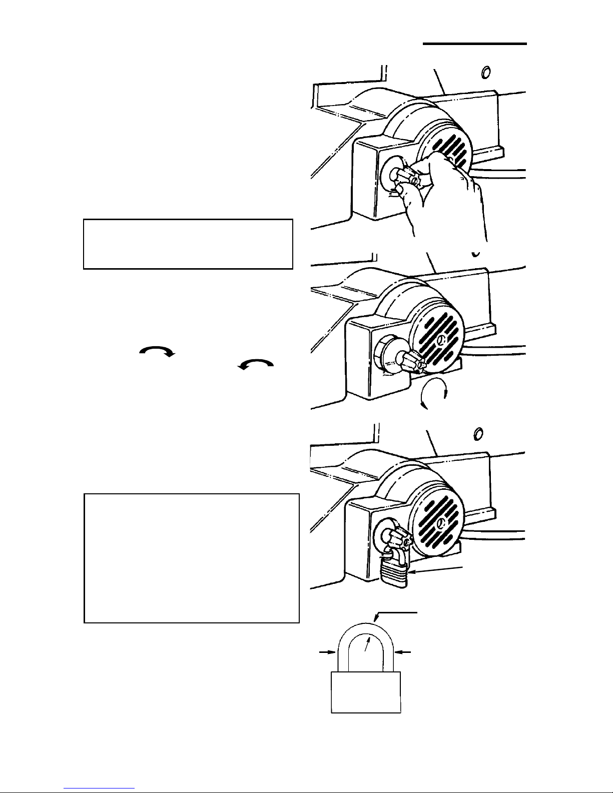
• With a flat blade screwdriver, turn motor
shaft by hand. Insert the screwdriver into
the slotted end of motor shaft located at
the center of the motor housing. Do this
while backing up the workpiece.
Before removing loose pieces from the
table, turn saw off and wait for all mov-
ing parts to stop.
Before Leaving the Saw
• Wait for all moving parts to stop.
•Make Workshop Child-proof. Unplug
the saw. Lock the workshop and ON/OFF
knob on the saw. Store the key awayfrom
children and others not qualified to use
the tool.

6
Glossary of Terms for Woodworking
Kerf - the slot cut by the blade.
Leading Edge - the edge of the work-
piece which is pushed into the blade first.
Sawblade Path - the area of the work-
piece directly in line with and moving
toward the sawblade edge.
Bevel - the ability to slant the table to
make angle cuts. An angle cutting opera-
tion through the face of the board.
Blade Tooth Set - the distance that the
edge of the sawblade toothis bent (or set)
outward from the side of the blade.
Plain End Blade - blade ends are flat,
and are clamped in the blade holders.
Pin End Blade - blade ends contain a pin
oriented at 90° to the blade. Blade ends
are hooked into a groove in the blade
holder and clamped.
Trailing Edge - the workpiece edge last
cut by the sawblade.
Workpiece - the item on which the cutting
operation is being performed.
Motor Specifications and Electrical Requirements
Power Supply and Motor Specifications
WARNING: To reduce the risk of
electrical hazards, fire hazards or
damage to the tool, use proper circuit
protection. Your tool is wired at the
factory for operation using the volt-
age shown. Connect tool to a power
line with the appropriate voltage and
a 15-amp branch circuit. Use a 15-
amp time delay type fuse or circuit
breaker. To reduce the risk of shock
or fire, if power cord is worn or cut, or
damaged in any way, have it replaced
immediately.
For replacement motor and control board,
refer to parts list in this manual.
CAUTION: A direct current motor is
used in this saw. Changes to the
internal wiring will create a fire haz-
ard and may also create a shock haz-
ard.
This machine is equipped with a variable
speed motor having the following specifi-
cations:
General Electrical Connections
DANGER: To reduce the risk of
electrocution:
• Use only identical replacement
parts when servicing. Servicing
should be performed by a qualified
service technician.
• Do not use in rain or where floor is
wet.
This tool is intended for indoor resi-
dential use only.
WARNING: Do not permit fingers to
touch the terminals of plug when
installing or removing the plug to or
from the outlet.
If power cord is worn or cut, or damaged
in any way, have it replaced immediately.
Voltage 110-120
Amperes 1.2
Hertz (Cycles) 60
Phase Single
RPM 500-1700
Rotation of Shaft Clockwise

7
110-120 Volt, 60 Hz. Tool Information
NOTE: The plug supplied on your tool
may not fit into the outlet you are planning
to use. Your local electrical code may
require slightly different power cord plug
connections. If these differences exist
refer to and make the proper adjustments
per your local code before your tool is
plugged in and turned on.
In the event of a malfunction or break-
down, grounding provides a path of least
resistance for electric current to reduce
the risk of electric shock. This tool is
equipped with an electric cord having an
equipment grounding conductor and a
grounding plug, as shown. The plug must
be plugged into a matching outlet that is
properly installed and grounded in accor-
dance with all local codes and ordi-
nances.
Do not modify the plug provided. If it will
not fit the outlet, have the proper outlet
installed by a qualified electrician.
A temporary adapter may be used to con-
nect this plug to a 2-pole outlet, as shown,
if a properly grounded outlet is not avail-
able. This temporary adapter should be
used only until a properly grounded outlet
can be installed by a qualified electrician.
The green colored rigid ear, lug and the
like, extension from the adapter must be
connected to a permanent ground such
as a properly grounded outlet box.
Improper connection of the equipment
grounding conductor can result ina risk of
electric shock. The conductor with insula-
tion having an outer surface that is green
with or without yellow stripes is the equip-
ment grounding conductor. If repair or
replacement of the electric cord or plug is
necessary, do not connect the equipment-
grounding conductor to a live terminal.
If the grounding instructions are not com-
pletely understood, or if you are in doubt
as to whether the tool is properly
grounded check with a qualified electri-
cian or service personnel.
WARNING: If not properly
grounded, this tool can cause an
electrical shock, particularly when
used in damp locations, in proximity
to plumbing, or out of doors. If an
electrical shock occurs there is the
potential of a secondary hazard,
such as your hands contacting the
sawblade.
NOTE: The adapter illustrated is for use
only if you already have a properly
grounded 2-prong outlet.
NOTE: Use of a temporary adapter is not
permitted by the Canadian Electrical
Code.
3-Prong Plug
Grounding
Prong
Properly
Grounded
Outlet
3-Prong
Adapter
Plug
Green
Grounding Lug
Make sure this
Is Connected
Ground
to a Known
2-Prong
Outlet

8
Motor Specifications and Electrical Requirements (continued)
Wire Sizes
NOTE: Make sure the proper extension
cord is used and is in good condition.
The use of any extension cord will cause
some loss of power. To keep this to a min-
imum and to prevent overheating and
motor burn-out, use the table shown to
determine the minimum wire size
(A.W.G.) extension cord.
Use only 3-wire extension cords which have
3-prong grounding type plugs and 3-pole
receptacles which accept the tools plug.
Unpacking and Checking Contents
Tools Needed
Unpacking
WARNING: To reduce the risk of
injury, from unexpected starting or
electrical shock, do not plug the
power cord into a power source outlet
during unpacking and assembly. This
cord must remain unplugged when-
ever you are working on the saw.
Your scroll saw is fully assembled and
shipped complete in one box.
IMPORTANT: Never lift this saw by the
arm which holds the blade or damage will
occur to your saw.
Separate all parts from packaging materi-
als and check each item with illustration
and "List of Loose Parts". Make certain all
items are accounted for before discarding
any packaging material.
NOTE: If you are missing any part, call 1-
800-4-RIDGID or E-mail us at info@ridg-
idwoodworking.com to get the missing
part. Sometimes small parts can get lost
in packaging material. DO NOT throw
away any packaging until saw is put
together. Check packaging for missing
parts before contacting RIDGID. A com-
plete parts list (Repair Parts) is at the end
of the manual. Use the list to identify the
number of the missing part.
List of Loose Parts
Item Description Qty.
A 16" Scroll Saw
(Completely Assembled)............... 1
BOwner’s Manual............................. 1
C Loose Parts Bag containing:
Blade........................................1
NOTE: Hardware to mount this scroll saw
to a bench is not supplied. See mounting
instructions for recommended hardware
size.
Extension
Cord Length Gauge
(A.W.G.)
110-120V
0-25 Ft.
26-50 Ft. 18
16
Combination Square Medium Standard and
Phillips Screwdriver
C
A
Lift Here
Lift
Do Not Lift Saw
Here
B
By This Arm

9
Getting to Know Your Scroll Saw
1. Height Adjustment Knob - Allows
for vertical positioning of blade guard/
hold down.
2. Blade Guard/Hold Down Knob -
Allows for secure angular positioning
of blade guard, work hold down and
sawdust blower.
3. Blade Holders - Retain and position
the blade.
4. Blade Guard - Defines area of mov-
ing blade.
5. Storage Drawer -For convenient
storage of pin and plain blades.
6. Bevel Scale - Shows angle table is
tilted for bevel cutting.
7. Bevel Indicator - Points to the
approximate angle of the blade in
relation to the table top.
8. Work Hold-Down and Blade Sup-
port - Provides added control of
workpiece, protection for operator
and support for the blade.
9. Sawdust Collection Port - Hook up
a wet/dry vac to help control sawdust.
10. Table Bevel Lock Knob - When
tightened, this knob secures table at
desired bevel angle. Loosening knob
allows the table to tilt up to 45° for
bevel cuts.
11. Blade Tension Knob - Tightening
the knob (clockwise) will increase the
tension on the blade. Loosening it
(counterclockwise) will decrease the
tension.
12. Table Stop - Allows table to be tilted
and returned to accurate 90° stop.
7 Bevel
Base
(Lift Here)
10 Table Bevel
Lock Knob 13 Speed Control
On/Off Knob
5 Storage
6 Bevel Scale
Frame
(Lift Here)
Arm
1 Height
Adjusting Knob
8 Work Hold-Down Foot
and Blade Support
11 Blade
Indicator
2 Blade Guard/Hold-Down Knob
3 Upper Blade Holder
4 Blade Guard
Blade
3 Lower Blade Holder
Drawer
Tension Knob
9Sawdust
Collection
Port
12 Table
Stop
Bearings

10
Getting to Know Your Scroll Saw (continued)
13. Speed Control/On-Off Knob - For
speed control setting, refer to the
“Choice of Blade and Speed” table.
The On-Off knob has a locking fea-
ture, This Feature Is Intended To
Help Prevent Unauthorized Use By
Children And Others.
• To turn machine “ON”, place fingers
on Speed Control/On-Off Knob and
pull out.
• To turn machine “OFF”, push in
Speed Control/On-Off Knob.
WARNING: Never leave the machine
unattended until it has come to a
complete stop.
The variable speed control may be
adjusted to the approximate speeds iden-
tified on the control panel. Suggested
speeds are identified under “Choice of
Blade and Speed”. Turn the control knob
clockwise to increase strokes per
minute and counterclockwise to
reduce the strokes per minute.
• To lock knob in “OFF” position, install
a padlock through the hole below
the knob as illustrated, and lock the
padlock. (Padlock is not supplied
with the saw.)
WARNING: For your own safety,
always push the knob “Off” when
machine is not in use. Also, in the
event of a power failure (all of your
lights go out), push knob “Off”.
“Lockout” your knob with a padlock
as shown. This will prevent the
machine from starting up again
when the power comes back on.
Rotate
Speed
Control
Install
Padlock
Through Hole
1 Inch Approximate
Approximate
Padlock Size
5/32 to 3/16 Inch
Approximate
Diameter

11
Alignment (Adjustments)
Changing the Table Bevel Angle
• The scroll saw work table can be tilted to
the left for bevel cutting up to 45° from
the 0° or horizontal cutting position.
• A bevel scale and indicator are provided
under the work table as a convenient ref-
erence for setting the approximate table
angle for bevel cutting.
• A 90° table stop is provided under the
table to allow the table to be tilted and
returned to an accurate 90°.
NOTE: A scroll saw is a scroll curve cut-
ting tool. It is not intended for making
precise angular cuts in wood. The indi-
cator is provided to give approximate
angular readings. A precision protractor
or square should be used to measure a
more precise blade to table angular loca-
tions.
To Adjust 90° Table Stop and Align
the Bevel Indicator
• Loosen the table bevel lock knob and
use a small square to set the table at 90°
to the blade.
• Loosen the table stop jam nut and adjust
the stop bolt in or out to accurate 90°.
• Tighten the jam nut.
• When there is no space between the
square and the blade, hold table in place
and tighten the bevel lock knob. The
table should now be approximately 90°
to the blade.
• Loosen the screw holding the bevel
scale pointer and adjust to 0°. Tighten
screw.
Remember, the bevel scale is a conve-
nient guide but should not be relied
upon for precision.
Bevel
Scale Bevel
Lock Knob
Bevel
Pointer

12
Adjusting Work Hold-down
WARNING: To reduce the risk of
injury from accidental starting,
always turn switch "OFF" and
unplug power cord from outlet
before removing or replacing the
blade.
The purpose of the work hold-down foot is
to hold the work against the table so that it
is less likely to lift with the up stroke of the
blade. It should lie flat on the workpiece
with the front prongs straddling the blade.
1.The work hold-down foot is attached to
the blade guard rod. The height of the
work hold-down foot is adjusted by
loosening the height adjustment knob
and moving the guide post up or down.
The work hold-down foot is adjusted
front to back and left-to-right by loosen-
ing the hold-down knob located on the
bracket, as illustrated.
2.When the table is tilted, the work hold-
down foot can be adjusted by loosening
the height adjustment knob and adjust-
ing the foot to the same angle as the
table. The work hold-down foot should
always be adjusted as close to the
blade as possible without touching it
and positioned directly on the surface of
the workpiece.
NOTE: For most applications tightening
the hold down knob with your fingers is
adequate.
Height Adjustment Knob
Hold-Down
Knob
Adjust
Hold-Down
Foot to
Same Angle
as Table
Alignment (Adjustments) (continued)
Over Tensioning Or Under
Tensioning Blade
Too much or too little blade tension could
cause blades to break rapidly.
The thicker, harder and more abrasive the
wood you are cutting, the more blades
you will have to use.
Blade breakage is caused by the follow-
ing:
• Over tension or under tension.
• Twisting or bending the blade.
• Over use - blade life exhausted.
•Over Aggressive Feeding of the work-
piece into the blade by going too fast.

13
Removing Pin End Blades
WARNING: To reduce the risk of
injury from accidental starting,
always turn switch "OFF" and
unplug power cord from outlet
before removing or replacing the
blade.
NOTE: Saw comes with 5" pin end blade
installed. If you are going to use 5" plain
end blades, refer to the instructions under
“Installing Plain End Blades”.
• Loosen tension on blade by turning ten-
sion knob counterclockwise at
least three full turns.
• Loosen upper and lower blade holder
knobs by turning the blade holder knobs
counterclockwise aboutthree full
turns. To make lower blade holder
access easier, tilt the table to 45°, and
raise the arms to the up position using a
screwdriver to rotate the motor shaft.
• Remove blade from the lower blade
holder by pushing down on the upper
arm, releasing the pin end blade from
the lower blade holder. Remove blade
from the upper blade holder by slightly
lifting up on the blade and pulling for-
ward.
NOTE: The table can be tilted to 45° to
increase access and visibility to lower
blade holder area.
Upper Blade
Holder Knob
Blade
Tension Knob
Loosen Upper
Blade
Holder
Lower Blade
Holder
Loosen
Pin

14
Alignment (Adjustments) (continued)
Installing 5" Pin End Blades
Pin end blade set up:
• Check that the blade tension knob is
loosened.
• Check that the upper and lower blade
holder knobs are loosened. Spread
blade holder jaws open using fingers.
NOTE: A rubber band looped around the
back of the blade holder will automatically
open the jaws when the knobs are loos-
ened which will make changing blades
easier.
• Install the blade through the opening in
the table with the teeth pointing down.
Engage the pin into the “V” notch of the
lower blade holder.
• Pull up on the blade and engage the
upper pin in the “V” notch of the upper
blade holder.
• Position the blade holders until you align
the front face of the blade holders with
the vertical edge of the blade. Tighten
upper and lower blade holder knobs by
turning knobs clockwise until the jaws
close evenly against the blade.
NOTE: To prevent blade holder damage,
do not use pliers to tighten knob.
• Carefully tighten the blade tension by
turning the tension knob clockwise
just until you feel the slack in the
blade is removed.
• Check to see that the pins are properly
located in the V-notch slot. Turn the ten-
sion knob an additional two full turns
clockwise. This amount of blade tension
should do well for most cutting opera-
tions and blades, but may vary by up to
one turn depending on blade thickness
and blade type.
• Make sure the blade is properly
installed. Before applying power, rotate
the motor shaft by hand using a screw-
driver in the motor shaft slot as shown.
WARNING: To reduce the risk of
injury from thrown objects, remove
all tools from the saw.
Tighten
Pin
“V”-Notch
Tighten
Rubber
Band
“V”-Notch
Tighten
Pin

15
Removing Plain End Blades
WARNING: To reduce the risk of
injury from accidental starting,
always turn switch “OFF” and
unplug power cord from outlet
before removing or replacing the
blade.
• Loosen tension on blade by turning ten-
sion knob counterclockwise at
least three full turns.
• Loosen the upper blade holder by turn-
ing the knob on the holder counterclock-
wise so the jaws open.
• Remove blade from upper blade holder.
• Loosen the lower blade holder knob in
the same way as the upper blade holder.
To make lower blade holder access eas-
ier, tilt the table to 45° and raise the
arms to the up position using a screw-
driver to rotate the motor shaft.
• Remove blade from lower blade holder.
Loosen
Loosen Upper
Blade
Holder
Lower Blade
Holder
Loosen

16
Installing 5" Plain End Blades
• Check that the blade tension knob is
loosened.
• Check that the upper and lower blade
holder knobs are loosened. Spread
blade holder jaws open using fingers.
NOTE: A rubber band looped around the
back of the blade holder will automatically
open the jaws when the knobs are loos-
ened which will make changing blades
easier.
NOTE: The table can be tilted to 45° to
increase access and visibility to lower
blade holder area.
• Install the blade through the hole in the
table and into the lower blade holder.
The blade teeth should point down. Posi-
tion the blade so that it is straight with
the front face of the blade holder and
blade end extends at least 1/8" below
the lower edge of the blade holder as
shown.
• Tighten the lower blade holder knob by
turning the knob clockwise
until the jaws close securely.
NOTE: To maintain blade holder clamping
force, keep finger knob threads cleaned
and oiled using all purpose household
machine (or motor) oil. To prevent blade
holder damage, do not use pliers to
tighten knob.
• Use the same procedure to install the
blade into the upper blade holder. Before
tightening the jaws using the upper
blade holder knob, adjust the position of
the blade, so that at least 1/8" extends
above the upper edge of the blade
holder as shown. Tighten the upper
blade holder knob by turning the knob
clockwise until the jaws close
securely.
• Carefully tighten the blade tension by turn-
ing the tension knob clockwise
until you feel the slack in the blade is
removed. Then turn the tension knob an
additional two turns. The number of turns
will be approximately two full turns, but
may vary by up to one turn depending on
blade thickness and blade type.
Tighten
Position Blade
As Shown
Upper Blade
Holder
Rubber
Band
1/8"
Min.
Lower Blade
Holder Tighten
Position Blade
As Shown
1/8" Min.
Alignment (Adjustments) (continued)

17
• Make sure the blade is properly
installed. Before applying power, rotate
the motor shaft by hand using a screw-
driver in the motor shaft as shown.
NOTE: To prevent blade holder damage,
do not use pliers to tighten knob.
Dust Blower
The dust blower will direct air to the most
effective point on the cutting line when the
hold down is adjusted. No adjustment is
necessary to the blower.
Blade Guard
The blade guard will always be positioned
parallel to the blade. No adjustment is
necessary.
Sawdust Collection Port
The collection port will help to control
sawdust. Simply attach a 1-1/4" wet/dry
vac hose into the opening.
Blade
Dust Blower
Guard
Sawdust Collection
Port

18
Mounting the Scroll Saw
Workbench Applications
• When mounting this saw to a workbench
a solid wood bench is preferred. A ply-
wood bench will cause noise and vibra-
tion to be more noticeable.
• Hardware to mount this saw to a work-
bench is not supplied with the saw.
However, we recommend the hardware
used be not smaller than the following.
Description Qty.
Hex Head Screw,
1/4-20 x length required ................. 4
Flat Washers, 1/4 I.D. ......................... 8
Lock Washers, 1/4 I.D......................... 4
Hex Nuts, 1/4-20................................. 8
• A soft foam pad to place between your
scroll saw and workbench is not sup-
plied with the saw. However, we highly
recommend the use of such a pad to
reduce noise and vibration.
Description Qty.
Soft foam pad such as carpet
padding, 24” x 12” x 1/2” ..................1
Do NOT over tighten mounting bolts -
leave some cushion in the foam pad for
absorbing noise and vibration.
NOTE: Through normal use sawdust
accumulates under the unit. Frequently
clean sawdust from under the unit to pre-
vent the linkage from binding, which could
overload and damage the motor.
Top View
Scroll Saw Base
Hex Head Screw
Workbench
Hex Head
Flat Washer
1/2" Foam Pad
(Optional)
Workbench
Flat Washer Hex Nut
Side View
Jam Nut
Lockwasher
Screw

19
Safety Instructions for Basic Saw Operations
Before Each Use
Inspect your saw.
Disconnect The Saw. To reduce the risk
of injury from accidental starting, turn the
switch “OFF”, unplug the saw before
changing the setup, removing covers,
guards or blade.
Check Damaged Parts. Check for:
• Alignment of moving parts.
• Binding of moving parts.
• Broken parts.
• Stable mounting.
• Any other conditions that may affect the
way the saw works.
• If any part is missing, bent or broken in
any way, or any electrical part doesn’t
work properly, turn the saw off and
unplug the saw. Replace damaged,
missing or failed parts before using the
saw again. Keep Guard In Place and in
working order.
Maintain Tools With Care. Keep the saw
clean for best and safest performance.
Follow instructions for lubricating.
•Use Only Recommended Accesso-
ries. Follow the instructions that come
with the accessories. The use of
improper accessories may cause risk of
injury to persons.
• Choose the right size and style blade for
the material and the type of cutting you
plan to do.
• Make sure the blade teeth point down-
ward, toward the table.
• Make sure the blade tension is properly
adjusted.
•Keep Work Area Clean. Cluttered areas
and benches invite accidents. Floor
must not be slippery.
To reduce the risk of burns or other fire
damage, never use the saw near flamma-
ble liquids, vapors or gases.
•Know Your Saw. Read and understand
the owners manual and labels affixed to
the tool. Learn its applications and limi-
tations as well as the specific potential
hazards peculiar to this tool.
• To reduce the risk of injury from acciden-
tal contact with moving parts, don't do
layout, assembly or setup work on the
saw while any parts are moving.
•Reduce the Risk of Accidental Start-
ing. Make sure switch is “OFF” before
plugging saw into a power outlet.
Plan your work.
•Use The Right Tool. Don't force tool or
attachment to do a job it was not
designed to do.
• Use this scroll saw to cut only wood,
wood-like products, plastics and nonfer-
rous metals.
CAUTION: This saw is NOT
designed for cutting ferrous metals
like iron or steel. When cutting non-
ferrous metals (brass, copper and
aluminum, etc.), metal shavings can
react withwood dust and start a fire.
To reduce the risk of fire:
• Remove all traces of wood dust
from inside the saw.
• Remove all traces of metal dust
from on or around the saw before
sawing wood again.
Plan Ahead To Protect Your Eyes, Hands, Face And Ears
Any power saw can throw foreign objects
into the eyes. This can cause permanent
eye damage. Wear safety goggles, not
glasses complying with ANSI Z87.1 (or in
Canada CSA Z94.3-99) shown on pack-
age. Everyday eyeglasses have only
impact resistant lenses. They are not
safety glasses. Safety goggles are avail-
able at many local retail stores. Glasses
or goggles not in compliance with ANSIor
CSA could seriously hurt you when they
break.

20
Safety Instructions for Basic Saw Operations (continued)
Dress for safety
• Do not wear loose clothing, gloves,
neckties or jewelry (rings, wristwatches).
They can get caught and draw you into
moving parts.
• Wear non-slip footwear.
• Tie back long hair.
• Roll long sleeves above the elbow.
• Noise levels vary widely. To reduce the
risk of possible hearing damage, wear
ear plugs or muffs when using saw for
hours at a time.
• For dusty operations, wear a dust mask
along with the safety goggles.
Inspect your workpiece.
Make sure there are no nails or foreign
objects in the part of the workpiece to be cut.
Use extra caution with large, very
small or awkward workpieces
• Never use this tool to finish pieces too
small to hold by hand.
• Use extra supports (tables, saw horses,
blocks, etc.) for any workpiece large
enough to tip when not held down to the
table top.
•Never use another person as a substi-
tute for a table extension, or as addi-
tional support for a workpiece or to help
feed, support or pull the workpiece.
• When cutting irregularly shaped work-
pieces, plan your work so it will not pinch
the blade. A piece of molding, for exam-
ple, must lay flat or be held by a fixture
or jig that will not let it twist, rock or slip
while being cut.
• Properly support round material such as
dowel rods or tubing. They have a ten-
dency to roll during a cut, causing the
blade to "bite". To avoid this, always use
a "V" block.
• Clear everything except the workpiece
and related support devices off the table
before turning the saw on.
Plan the way you will hold the work-
piece from start to finish.
• Do not hand hold pieces so small that
your fingers will go under the blade
guard. Keep your hands away from the
blade.
• Reduce the Risk of awkward operations
and hand positions where a sudden slip
could cause fingers or hand to move into
the blade.
•Don’t Overreach. Keep good footing
and balance.
• Keep your face and body to one side of
blade, out of line with a possible thrown
piece if the blade should break.
Whenever Saw Is Running
WARNING: Don’t let familiarity
(gained from frequent use of your
saw) cause a careless mistake. A
careless fraction of a second is
enough to cause a severe injury.
• Before starting your cut, watch the saw
while it runs. If it makes an unfamiliar
noise or vibrates a lot, stop immediately.
Turn the saw off. Unplug the saw. Do not
restart until finding and correcting the
problem.
•Keep Children Away. Keep all visitors a
safe distance from the saw. Make sure
bystanders are clear of the saw and
workpiece.
•Don’t Force Tool. It will do the job better
and safer at its designed rate. Feed the
workpiece into the saw blade only fast
enough to let it cut without bogging down
or binding.
Before freeing any jammed material:
• Turn switch “OFF”.
• Wait for all moving parts to stop.
• Unplug saw.
When backing up the workpiece, the
blade may bind in the kerf (cut). This is
usually caused by sawdust clogging
up the kerf. If this happens:
• Turn switch “OFF”.
• Wait for all moving parts to stop.
• Unplug saw.
• With a flat blade screwdriver, turn the
motor by hand while backing up the
workpiece.
Before removing loose pieces from the
table, turn saw off and wait for all mov-
ing parts to stop.
This manual suits for next models
1
Table of contents
Languages:
Other RIDGID Saw manuals

RIDGID
RIDGID TS3612 User manual

RIDGID
RIDGID 550 User manual

RIDGID
RIDGID R8642 User manual

RIDGID
RIDGID R8641 User manual

RIDGID
RIDGID R3030 User manual

RIDGID
RIDGID R4510 User manual

RIDGID
RIDGID R3020 User manual

RIDGID
RIDGID R48607 User manual

RIDGID
RIDGID BS1400 User manual

RIDGID
RIDGID R884 User manual

RIDGID
RIDGID R8642VN User manual

RIDGID
RIDGID 5228 User manual

RIDGID
RIDGID R4031 User manual

RIDGID
RIDGID R4231 User manual

RIDGID
RIDGID MS1060 User manual

RIDGID
RIDGID ms12500 User manual

RIDGID
RIDGID R4511 User manual

RIDGID
RIDGID R3020 User manual

RIDGID
RIDGID PCS-500 User manual

RIDGID
RIDGID 932-VS User manual