manuals.online logo
Brands
  1. Home
  2. •
  3. Brands
  4. •
  5. RIDGID
  6. •
  7. Security Sensor
  8. •
  9. RIDGID NAVITRACK User manual

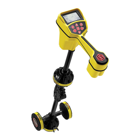
RIDGID NAVITRACK User manual

))))
))
Sound Key
Mode Key
Menu Key
Power ON/OFF Key
Keypad & Screen Reference
Up Key
Menu Navigation/Signal
Capture/1000 Set (3 sec. press)
Down Key
Menu Navigation/Depth Average
& Hold/Zero Set (3 sec. press)
Select Key
View Toggle/ Menu
Selection
Sonde Frequency
Sonde Level
Active Trace Frequency
Active Trace Level
Passive (AC) Trace Frequency
Passive (AC) Trace Level
Audio Level
Battery Level
Distance (Depth)
Current Strength
Auto Gain Step
Numeric Horizontal
Angle Indicator
2D Horizontal Field
Angle Indicator
Overhead Indicator
Distance Units
Signal Capture – When activated
(Search View only)
Active View (Search
view shown in gray for
illustration purposes)
Backlight Icon
Use Select Key to select
highlighted item.
Use Up or Down keys to choose
desired information level. Then use
Select Key to select highlighted item;
NaviTrack returns to the Active View
The NaviTrack has three levels of information to choose from. Entering this
menu will allow the user to choose the amount of information displayed on
the screen.
Press Menu Key once to
open the Main Menu.
Main Menu
Info Level Menu
Selected Menu Item
Selected Menu Item
Setting Information Level
Use Up or Down keys to
choose menu item
Display Screen
Keypad
Handle
Serial Number
Label
Icon list Label
Headphone
Jack (under
cover) Lower Antenna
Distance
Measure Point
Upper Antenna
Antenna Mast
Markers
Battery
Compartment Install four (4) C-cell batteries
Identification & Setup
Speaker
TM
Quick Start Guide – NaviTrack Sonde & Line Locator
Selecting Operating Mode & Frequency
Line Trace Mode
Sonde Mode
Passive (AC)
Trace Mode
Use Select Key to select
highlighted item; NaviTrack
returns to the Active View
Press Mode Key once to
open the Mode Menu. Press
Mode Key again to open the
highlighted mode’s
Frequency Menu
NOTE: If available frequencies do not match
your transmitting equipment, a new set of
frequencies may be loaded. See “Configuration
Menu” section of Operator’s Manual for details.
Use Up or Down keys to
choose menu item
Mode Menu
Frequency Menu
Selected Mode and
Active Frequency
Operating Mode
Selected Frequency
Open Sound Menu
Setting Sound Level
Sound Level Menu
Choose menu item
Select highlighted
item
Depth Average & Hold
See User Manual for details
Averages the depth reading over a four (4) second interval and holds the reading on the
display. Press once to take reading, press again to return to real time depth
display. Icon shown when depth held. Depth readings are available in feet and
inches (xx’ xx”), decimal feet (xx.xx’), and meters (xx.xx m).
Iconshown when
depth averaged over the
pole.
NOTE: Cycle power ON/OFF to reset 1000 Level and Zero Set to default levels.
Note: Icons used on the
label are also used on the
LCD display, and have the
same meanings
1. Select the Sonde operating mode and select the frequency that
matches your sonde (most cameras are 512Hz).
2. With the sonde turned off, zero the display by pressing the Down key
until the unit “dings” (~3 sec). (Optional; eliminates stray electrical
signals to make detection easier).
3. Starting with the NaviTrack in Search View and near the suspected
sonde location, hold NaviTrack so the mast is horizontal and extend
your arm. Make a slow circle (see illustration below) while observing
the signal strength; it will be highest when the mast is pointed in the
sonde’s direction.
4. Lower NaviTrack to its normal operating position (mast vertical) and
walk in the direction of the sonde. As you approach the sonde, the
signal strength will increase. When it begins to decrease, stop walking
and switch to Map View (to switch press the Select key).
5. Locate the Pole icon on the display (see Map View illustration). With
the mast vertical, move NaviTrack until the Pole icon is centered on the
crosshairs. Place one of the orange markers on the ground at this spot.
6. Locate the Sonde icon on the display (see Map View illustration) move
toward Sonde icon along the estimated pipe axis (double line). After
you cross over the Equator (dotted line), the second Pole will appear.
Center the pole on the crosshairs and mark its position as before.
7. Move back toward the Equator. With the mast vertical and the lower
antenna ball in line with the Pole markers, center the dashed Equator
line on the crosshairs. Place the yellow marker at this spot.
8. Verify the locate: all three markers aligned, signal strength highest and
depth lowest directly over the yellow marker. See the user manual for
more information and exceptions to the above, e.g. tilted sondes.
Use Select Key to toggle between
Search and Map Views
Maximum Signal Marker –
marks the strongest signal
measured
Signal Strength Gauge –
clockwise movement
indicates signal increase
Signal Strength – higher
numbers indicate stronger
closer signal, closer to sonde
Mini Map – condensed Map
View; visual cues indicate
sonde location (see Map
View below)
Signal Capture–
will display here
Sonde Mode
Search View (default) shown
shown Maximum Signal Strength Indicator
Map View
Zoom Ring – large ring
appears when display is
zoomed (over poles)
Equator – dotted line shows
position of equator
Sonde Axis – shows
approximate direction of pipe;
more accurate above pipe
Signal Strength – higher
numbers indicate stronger
closer signal, closer to sonde
Pole Icon – shows position of
nearest pole
Sonde Icon – Symbol/icon
indicating the field angle is
horizontal.
Pole
Equator
Pole
Map View over each pole Map View over equator
Sweep to
find direction
of sonde.
Mark poles
and equator.
Line & Passive (AC) Trace Modes
1. Determine the frequency of your Line Transmitter.
2. Select the NaviTrack Trace operating Mode and select the
frequency you plan to use.
3. Use the Select Key to Toggle to the Map View (if needed).
4. (Optional) Zero Set: With the Line Transmitter turned off, press the
Down Key for 3 sec to set the “Transmitter Off” Signal Strength
Baseline to 0.0 to make detection easier.
5. Energize the line to be traced. Verify that the indicated signal
strength increases significantly if you are near the transmitter.
Place the lower antenna near either the ground wire (black) or the
direct connection (red) wire and confirm you have a steady solid
tracing line on the display. If the Line Transmitter is in inductive
mode you should see a very large signal anywhere near the
Transmitter.
6. Trace the line.
7. (Optional) 1000 Set: Centered over the line, with a strong signal
present, press the Up Key for 3 sec to set the Signal Strength and
Current Level reading both to a “normalized” value of 1000.
When the Lower Antenna Signal (solid line) is centered on the Map
View, you are above the energized line. If the Upper Antenna Signal
(dotted line) is significantly aligned with Lower Antenna Signal the field
is undistorted.
See the user manual for more information and exceptions to the above.
Map View (default)
Use Select Key to toggle between
Search and Map Views
Traced Line (solid) – lower
antenna, shows position of
energized line
Traced Line (dotted) – upper
antenna, must be aligned for
good locate and depth
Signal Strength – higher
numbers indicate stronger
closer signal, closer to line
shown
shown
Search View
Signal Strength – higher
numbers indicate stronger
closer signal, closer to line
Mini Map – condensed Map
View, visual cues indicate line
location (see Map View
above)
Maximum Signal Marker – marks
the strongest signal measured
Signal Strength Gauge –
clockwise movement
indicates signal increase
Other manuals for NAVITRACK

5

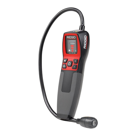
Other RIDGID Security Sensor manuals

RIDGID SeekTech SR-20 User manual

RIDGID

RIDGID SeekTech SR-20 User manual

RIDGID SeekTech SR-20 User manual

RIDGID

RIDGID SeekTech SR-20 User manual

RIDGID micro CD-100 User manual

RIDGID

RIDGID micro CD-100 User manual

RIDGID micro CD-100 User manual

RIDGID

RIDGID micro CD-100 User manual

RIDGID A-Frame Fault Locator User manual

RIDGID

RIDGID A-Frame Fault Locator User manual

RIDGID NaviTrack Battery Sonde User manual

RIDGID

RIDGID NaviTrack Battery Sonde User manual

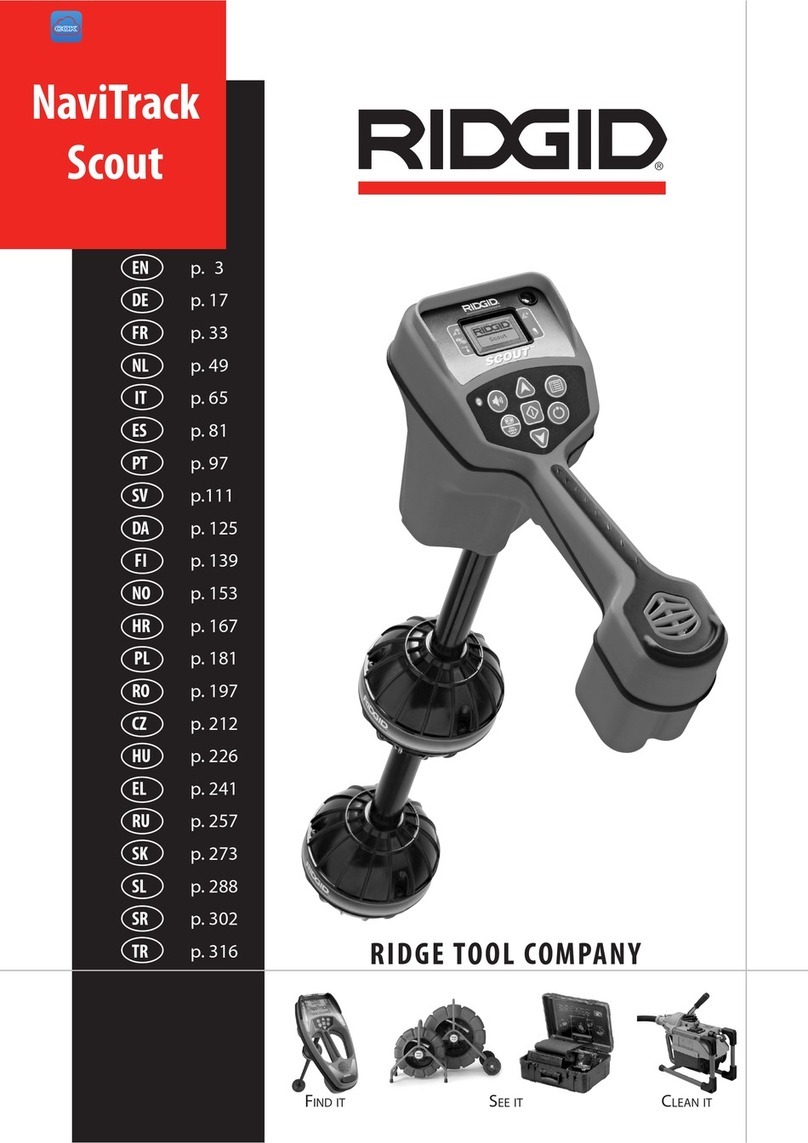
RIDGID NaviTrack Scout User manual

RIDGID

RIDGID NaviTrack Scout User manual

RIDGID A-Frame User manual

RIDGID

RIDGID A-Frame User manual

Popular Security Sensor manuals by other brands

EMX Industries MVP D-TEK instruction manual

EMX Industries

EMX Industries MVP D-TEK instruction manual

Digital Watchdog SiteWatch DW-DTPIRIPW quick start guide

Digital Watchdog

Digital Watchdog SiteWatch DW-DTPIRIPW quick start guide

GMI D1033D quick start guide

GMI

GMI D1033D quick start guide

HP 5973 Hardware installation manual

HP

HP 5973 Hardware installation manual

VOLTCRAFT LSG-4 operating instructions

VOLTCRAFT

VOLTCRAFT LSG-4 operating instructions

CNDINGTEK DF703 manual

CNDINGTEK

CNDINGTEK DF703 manual

Amprobe RLD-1 user manual

Amprobe

Amprobe RLD-1 user manual

UniPOS FD 7110 instruction manual

UniPOS

UniPOS FD 7110 instruction manual

Numens HNC-310 installation instructions

Numens

Numens HNC-310 installation instructions

Bentel Security BL151 manual

Bentel Security

Bentel Security BL151 manual

Potter PAD100-LFSB installation manual

Potter

Potter PAD100-LFSB installation manual

urmet domus 1051 quick guide

urmet domus

urmet domus 1051 quick guide

Intelbras VP 5311 MW Pet user manual

Intelbras

Intelbras VP 5311 MW Pet user manual

Fnirsi FNIRSI-WD-02 instruction manual

Fnirsi

Fnirsi FNIRSI-WD-02 instruction manual

Elcometer 500 operating instructions

Elcometer

Elcometer 500 operating instructions

Elkron IRP600 manual

Elkron

Elkron IRP600 manual

Renkforce 1168612 operating instructions

Renkforce

Renkforce 1168612 operating instructions

LEGRAND EMOS G1130 manual

LEGRAND

LEGRAND EMOS G1130 manual

manuals.online logo
manuals.online logoBrands
  • About & Mission
  • Contact us
  • Privacy Policy
  • Terms and Conditions

Copyright 2025 Manuals.Online. All Rights Reserved.