Riello Elettronica Cardin BL Series User manual

ZVL589.01 Mod: 10.04.2018
AUTOMAZIONI A VITE SENZA FINE PER CANCELLI A BATTENTE
WORM SCREW AUTOMATION FOR SWING-TO GATES
AUTOMATISMES À VIS SANS FIN POUR PORTAILS BATTANTS
DREHTORANTRIEBE MIT GEWINDESPINDEL
AUTOMATIZACIONESDETORNILLOSINFÍNPARACANCILLASDEBATIENTE
AANDRIJVING MET WORMSCHROEF VOOR DRAAIPOORTEN
Questoprodottoèstatotestatoecollaudatoneilaboratoridellacasacostruttrice,laqualenehaverificatolaperfettacorrispondenzadellecaratteristiche
con quelle richieste dalla normativa vigente. This product has been tried and tested in the manufacturer's laboratory who have verified that the
product conforms in every aspect to the safety standards in force. Ce produit a été testé et essayé dans les laboratoires du fabriquant. Pour l'installer
suivre attentivement les instructions fournies. Dieses Produkt wurde in den Werkstätten der Herstellerfirma auf die perfekte Übereinstimmung ihrer
EigenschaftenmitdenvondengeltendenNormenvorgeschriebenengetestetundgeprüft. Este producto ha sidoprobadoyensayadoenlos laboratorios
delfabricante, que hacomprobado la perfecta correspondencia de sus características con las contempladaspor la normativavigente. Dit product is
getestengoedgekeurdin de fabriek van de fabrikant die heeft vastgesteld dat de producteigenschappen volledig aandegeldendevoorschriftenvoldoen.
BL
24Vdc
Motors
Model Date
Instruction manual Series
BL EGOS - ESOL 05-04-2016
ZVL589.01
CARDIN ELETTRONICA spa
Via del lavoro, 73 – Z.I. Cimavilla
31013 Codognè (TV) Italy
Tel: +39/0438.404011
Fax: +39/0438.401831
Http: www.cardin.it
®
BLEGOS
BLESOL
24 Vdc Motors
ITALIANO
ENGLISH
FRANÇAIS
DEUTSCH
ESPAÑOL
Installation example Page 2
Assembly Pages 3-5
Wiring diagram (installation example) Page 6
Important remarks Page 9
Installation instructions Pages 9-10
Manual manoeuvre Page 10
Electrical connection Page 10
Maintenance Page 10
Technical specications Page 20
Exemple d’installation Page 2
Schéma de montage Pages 3-5
Schéma électrique (exemple d’installation) Page 6
Consignes importantes Page 11
Instructions pour l’installation Pages 11-12
Manœuvre manuelle Page 12
Branchement électrique Page 12
Maintenance Page 12
Caractéristiques techniques Page 20
Anlagenart Seite 2
Montagegearbeiten Seiten 3-5
Elektrischer Schaltplan (Anlagenart) Seite 6
Wichtige Hinweise Seite 13
Installationsanleitung Seiten 13-14
Manuelle Betätigung Seite 14
Elektrischer Anschluss Seite 14
Wartung Seite 14
Technische Eigenschaften Seite 20
Instalación estándar Página 2
Esquema de montaje Páginas 3-5
Esquema eléctrico (instalación estándar ) Página 6
Advertencias importantes Página 15
Instrucciones para la instalación Páginas 15-16
Maniobra manual Página 16
Conexionado eléctrico Página 16
Mantenimiento Pagina 16
Características técnica Página 20
Esempio di installazione Pagina 2
Schema di montaggio Pagine 3-5
Schema elettrico (impianto tipo) Pagina 6
Avvertenze importanti Pagina 7
Istruzioni per l'installazione Pagine 7-8
Manovra manuale Pagina 8
Collegamento elettrico Pagina 8
Manutenzione Pagina 8
Caratteristiche tecniche Pagina 20
NEDERLANDS
Installatievoorbeeld Blz. 2
Montageschema Blz. 3-5
Standard bedradingschema Blz. 6
Belangrijke opmerkingen Blz. 17
Installatievoorschriften Blz. 17-18
Handmatige beweging Blz. 18
Elektrische aansluiting Blz. 18
Onderhoud Blz. 18
Technische specicaties Blz. 20

2
230V
50Hz
RX
TX
12
11
4
3
1
7
14
2
13
9
10
5
8
6
15
15
1
ESEMPIO D'INSTALLAZIONE - INSTALLATION EXAMPLE - EXEMPLE D'INSTALLATION
ANLAGENART - INSTALACIÓN ESTÁNDAR - INSTALLATIEVOORBEELD
LEGENDA
1 Motoriduttore (sinistra)
2 Motoriduttore (destra)
3 Fotocellula interna
4 Fotocellula esterna
5 Lampeggiatore
6 Selettore a chiave
7 Elettroserratura
8 Antenna esterna (Cavo coassiale
RG58 Impedenza 50Ω)
9 Interruttore onnipolare con apertura
contatti min. 3 mm
10 Cavo alimentazione principale 230 Vac
11 Canalatura per cavo Cardin CABPC10
12 Canalatura per collegamenti a bassa tensione
13 Programmatore elettronico
14 Fotocellule laterali di protezione (FS)
15 Battuta di apertura
Attenzione: Lo schema rappresentato è puramente indicativo e viene fornito come base
di lavoro al ne di consentire una scelta dei componenti elettronici Cardin da utilizzare.
Detto schema non costituisce pertanto vincolo alcuno per l'esecuzione dell'impianto
LEGEND
1 Geared motor (left)
2 Geared motor (right)
3 Internal photocells
4 External photocells
5 Warning lights
6 Mechanical selector switch
7 Electric locking device
8 External antenna (RG58 coaxial cable - impedance 50Ω)
9 All-pole circuit breaker with a minimum of 3 mm between the contacts
10 Mains cable 230 Vac
11 Channelling for the Cardin connection cable CABPC10
12 Channelling route for low voltage wires
13 Electronic programmer
14 Lateral protective photocells (FS)
15 Opening travel limit
Attention: The drawing is purely indicative and is supplied as working base from which
to choose the Cardin electronic components making up the installation. This drawing
therefore does not lay down any obligations regarding the execution of the installation.
NOMENCLATURE
1 Motoréducteur (gauche)
2 Motoréducteur (droit)
3 Cellule photoélectrique intérieure
4 Cellule photoélectrique extérieure
5 Clignoteur
6 Contact à clé
7 Serrure électrique
8 Antenne (Câble coaxial RG58 - Impédance 50Ω)
9 Interrupteur omnipolaire avec ouverture des contacts d'au moins 3 mm
10 Câble d’alimentation principale 230 Vac
11 Chemin pour câble Cardin CABPC10
12 Chemin pour branchements basse tension
13 Programmateur électronique
14 Cellules photoélectriques latérales de protection (FS)
15 Butée en ouverture
Attention: le schéma, diffusé à titre purement indicatif, est destiné à vous aider dans
le choix des composants électroniques Cardin à utiliser. Par conséquent, il n'a aucune
valeur obligatoire quant à la réalisation de l'installation.
ZEICHENERKLÄRUNG
1 Getriebemotor (links)
2 Getriebemotor (rechts)
3 Interne Lichtschranke
4 Externe Lichtschranke
5 Blinklicht
6 Schlüsselschalter
7 Elektroverriegelung
8 Antenne (Koaxialkabel RG58 Impedanz 50Ω)
9 Allpoliger Schalter mit Kontaktenabstand von mindestens 3 mm
10 Hauptversorgungskabel 230 Vac
11 Kanalverlauf für Verbindungskabel Cardin CABPC10
12 Kanalverlauf für Anschluss auf Niederspannung
13 Steuerungseinheit
14 Seitliche Schutz-Lichtschranken (FS)
15 Öffnungsanschlag
Achtung: Bei dem dargestellten Plan handelt es sich nur um ungefähre Angaben
und er wird als Arbeitsgrundlage geliefert, um eine Auswahl der zu benutzenden
elektronischen Komponenten von Cardin zu erlauben. Der besagte Plan ist daher für
die Ausführung der Anlage nicht bindend.
LEYENDA
1 Motorreductor (izquierda)
2 Motorreductor (derecha)
3 Fotocélula interior
4 Fotocélula exterior
5 Relampagueador
6 Selector con llave
7 Electrocerradura
8 Antena exterior (Cable coaxial RG58 Impedancia 50Ω)
9 Interruptor omnipolar con apertura entre los contactos de 3 mm. como mín.
10 Cable de alimentación principal 230 Vac
11 Canaleta para cable CABPC10 Cardin
12 Canaleta para el conexionado a baja tensión
13 Centralita electrónica
14 Fotocélulas laterales de protección (FS)
15 Tope de apertura
Atención: La pantalla que se muestra es sólo indicativa y se suministra como base
de trabajo, con el n de permitir una elección de los componentes electrónicos Cardin
por utilizar; en consecuencia, dicho esquema no constituye vínculo alguno para la
ejecución del sistema.
LEGENDE
1 Reductiemotor (links)
2 Reductiemotor (rechts)
3 Fotocellen binnenzijde poort
4 Fotocellen buitenzijde poort
5 Waarschuwingslamp
6 Sleutelcontact
7 Elektrisch slot
8 Externe antenne (coaxkabel RG58 impedantie 50Ω)
9 Meerpolige onderbrekingsschakelaar met contactafstand van minstens 3 mm
10 Hoofdvoedingskabel 230 Vac
11 Kabelgoot voor Cardin kabel CABPC10
12 Kabelgoot voor laagspanningsaansluitingen
13 Elektronische besturingsunit
14 Fotocellen voor zijdelingse bescherming (FS)
15 Openingsbegrenzer (stopbuffer)
Opgelet: De tekening is alleen voor informatieve doeleinden en is bedoeld om u te
helpen bij de keuze van de elektronische componenten van Cardin. Deze tekening
mag dan ook niet beschouwd worden als bindend voor het uitvoeren van de installatie.

3
SCALA: 1:2
BLEGOS /ESOL
17-01-2016
DI0673 Description :
Product Code :
Date :
Drawing number :
P.J.Heath
CARDIN ELETTRONICA S.p.A - 31020 San Vendemiano (TV) Italy - via Raffaello, 36 Tel: 0438/401818 Fax: 0438/401831
Draft :
All rights reserved. Unauthorised copying or use of the information contained in this document is punishable by law
SCHEMA DI MONTAGGIO BLEGOS
1
4
11
3
5
67
8
9
10
2
12
13
14
14
2
SCHEMA DI MONTAGGIO
ASSEMBLY
MONTAGE
MONTAGEGEARBEITEN
ESQUEMA DE MONTAJE
MONTAGESCHEMA
BLEGOS / BLESOL
CORSA UTILE - TRAVEL DISTANCE - COURSE UTILE
ARBEITSHUB - CARRERA UTIL - SLAGLENGTE
'BLEGOS' = 390 mm - 'BLESOL' = 540 mm 3
DIMENSIONI D'INGOMBRO - EXTERNAL DIMENSIONS - DIMENSIONS D'ENCOMBREMENT
AUSSENABMESSUNGEN - DIMENSIONES MAXIMAS - AFMETINGEN
131
18 806
890
390
66
416
131
18 956
1040
540
66
416
BLEGOS
BLESOL
Protezione antipolvere - Anti-dust protective sheathes
Protection anti-poussière - Staubschutz
Protección antipolvo - Stofbescherming
2a

4
SCALA: 1:2
BLEGOS-ESOL
05-04-2016
DI0685 Description :
Product Code :
Date :
Drawing number :
P.J.Heath
CARDIN ELETTRONICA S.p.A - 31020 San Vendemiano (TV) Italy - via Raffaello, 36 Tel: 0438/401818 Fax: 0438/401831
Draft :
All rights reserved. Unauthorised copying or use of the information contained in this document is punishable by law
limite d'impiego
a
H max.
2
A
C
B
H min
1
L
C
2
120
LIMITI D’IMPIEGO - LIMITS OF USE - CONTRAINTES D'UTILISATION - ANWENDUNGSGRENZEN - LIMITES DE EMPLEO
4
ESEMPIO D’INSTALLAZIONE-INSTALLATION EXAMPLE-EXEMPLE D'INSTALLATION-INSTALLATIONSART-EJEMPLO DE INSTALACIÓN
5
SCALA: 1:
CARDIN BLEGOS
BL2EGOS-ESOL
05-04-2016
DI0686 Description :
Product Code :
Date :
Drawing number :
P.J.Heath
CARDIN ELETTRONICA S.p.A - 31020 San Vendemiano (TV) Italy - via Raffaello, 36 Tel: 0438/401818 Fax: 0438/401831
Draft :
All rights reserved. Unauthorised copying or use of the information contained in this document is punishable by law
Installazione tipo
a
2
1
3
SBLOCCO MANUALE - MANUAL RELEASE - DÉVERROUILLAGE MANUEL - MANUELLE ENTRIEGELUNG - DESBLOQUEO MANUAL
6a 6b 6c
6d 6e
Lock
Unlock
BLEGOS (H min. 420 - H max. 800)
a° A B C C2 L
90 132 200 0 132 600
90 132-182 200 0 - 50 132 600
90 183-203 180 51 - 70 132 620
90 204-224 160 71 - 90 132 640
90 183-203 160 91-110 92 630
90 204-224 150 110-130 92 650
110 132 200 0 132 600
110 132-182 180 0 - 50 132 620
110 183-203 170 51 - 70 92 630
110 204-224 160 71 - 90 92 640
BLESOL (H min. 420 - H max. 950)
a° A B C C2 L
90 132 240 0 132 700
90 132-182 220 0 - 50 132 720
90 183-203 210 51 - 70 132 720
90 204-224 200 71 - 90 132 730
90 183-203 180 91-110 92 740
90 204-224 180 110-130 92 760
110-120 132 240 0 132 700
110-120 132-182 220 0 - 50 132 720
110° 183-203 210 51 - 70 132 720
110° 204-224 200 71 - 90 132 730
110° 183-203 180 91-110 132 740
110° 204-224 180 110-130 132 760
C2
132
mm
92
mm
INSTALLATIEVOORBEELD
HANDMATIGE ONTGRENDELING
GEBRUIKSGRENZEN

5
7
8
9
BL
05-04-2016
DI0689 Description :
Product Code :
Date :
Drawing number :
P.J.Heath
CARDIN ELETTRONICA S.p.A - 31020 San Vendemiano (TV) Italy - via Raffaello, 36 Tel: 0438/401818 Fax: 0438/401831
Draft :
All rights reserved. Unauthorised copying or use of the information contained in this document is punishable by law
Installazione squadretta posteriore 44 mm
40 mm
40 mm
STAFFA POSTERIORE - REAR BRACKET
PATTE POSTÉRIEURE - HINTERER HALTEBÜGEL
SOPORTE POSTERIOR - ACHTERSTE BEUGEL
SCALA: 1:2
Prodotti BLEGOS - BLESOL
BLEGOS - BLESOL
05-04-2016
DI0688 Description :
Product Code :
Date :
Drawing number :
P.J.Heath
CARDIN ELETTRONICA S.p.A - 31020 San Vendemiano (TV) Italy - via Raffaello, 36 Tel: 0438/401818 Fax: 0438/401831
Draft :
All rights reserved. Unauthorised copying or use of the information contained in this document is punishable by law
Staffa attacco cancello
STAFFA POSTERIORE REGOLABILE - FITTING THE ADJUSTABLE REAR BRACKET
PATTE POSTÉRIEURE RÉGLABLE - HINTERER, EINSTELLBARER HALTEBÜGEL
SOPORTE POSTERIOR REGULABLE - VERSTELBARE ACHTERSTE BEUGEL
STAFFA ANTERIORE REGOLABILE - FITTING THE ADJUSTABLE FRONT BRACKET
PATTE ANTÉRIEURE RÉGLABLE - VORNER, EINSTELLBARER HALTEBÜGEL
SOPORTE ANTERIOR REGULABLE - VERSTELBARE VOORSTE BEUGEL
PREINSTALLAZIONE STAFFA POSTERIORE/ANTERIORE - PRE-INSTALLATION FRONT/REAR BRACKET
PRÉINSTALLATION PATTE POSTÉRIEURE/ANTÉRIEURE - VORMONTAGE HINTERER/VORNER HALTEBÜGEL
PREINSTALACIÓN SOPORTE POSTERIOR/ANTERIOR - VOORINSTALLATIE VOORSTE EN ACHTERSTE BEUGEL
7
8
9
SCALA: 1:2
Prodotti BLEGOS - BLESOL
BLEGOS-ESOL
05-04-2016
DI0687 Description :
Product Code :
Date :
Drawing number :
P.J.Heath
CARDIN ELETTRONICA S.p.A - 31020 San Vendemiano (TV) Italy - via Raffaello, 36 Tel: 0438/401818 Fax: 0438/401831
Draft :
All rights reserved. Unauthorised copying or use of the information contained in this document is punishable by law
Staffa attacco pilastro
A
132
mm
92
mm
STAFFA ANTERIORE - FRONT BRACKET
PATTE ANTÉRIEURE - VORNER HALTEBÜGEL
SOPORTE ANTERIOR - VOORSTE BEUGEL

6
2
3
1
4
6
OK
NO
5
SCHEMA ELETTRICO IMPIANTO TIPO - STANDARD WIRING DIAGRAM - SCHÉMA ÉLECTRIQUE DE L'EXEMPLE D'INSTALLATION
ELEKTRISCHER SCHALTPLAN ANLAGENART - ESQUEMA ELÉCTRICO INSTALACIÓN ESTÁNDAR - STANDARD BEDRADINGSSCHEMA
10
Collegamenti scheda base
CC2X24 (V1.00)
18-07-2016
DI0762 Description :
Product Code :
Date :
Drawing number :
P.J.Heath
CARDIN ELETTRONICA S.p.A - 31020 San Vendemiano (TV) Italy - via Raffaello, 36 Tel: 0438/401818 Fax: 0438/401831
Draft :
All rights reserved. Unauthorised copying or use of the information contained in this document is punishable by law
CENTRALINA 2 MOTORI CC CON ENCODER
(con display LCD - MULTI-CODIFICA)
2
1
TB
SEL
1
32
24V 12V 0
C
1
65432
NA
NC NC
C
NA
FTC-RX
1
32
24V
12V
0
FTC-TX
2
1
LP
1
2
LS
2
1
TD
29 30 31
9 10 11 12 13 14 15 16 17 18 19 20 21 22 23 24 25 26
7 8
3 4 5 6
1 2 3 4 5 6
1 2
Yw
Gy
Gr
Bl
ENCODER 1 Yw
Gy
Gr
Bl
ENCODER 2
M1 M2
27 28
TD
TA
TC
24Vdc
TAL
CMN
FI
TB
CP
FS
EMRG1
EMRG2
CMN
CMN
CTRL
24Vdc
CMN
LS
LP
CMN
LC/CH2
ELS
12Vdc
CMN
ANS400
ANQ800-1
3 4 5 6
12
Bl Gr Gy Yw
M1 ENCODER 1
RdBk
M1
3 4 5 6
12
Bl Gr Gy Yw
M2 ENCODER 2
RdBk
PC PC
M2
CS1422A DC0556
B1
TRANSFORMER
L1
F1
PROG/OK
J5
COLORE COLOUR CODE COULEURS
CABLAGGI CODE DES CÂBLES
Bl Blu Blue Bleu
Gr Verde Green Vert
Gy Grigio Grey Gris
Yw Giallo Yellow Jaune
KABELFARBEN COLORACIÓN KABELKLEUREN
CABLEADOS
Bl Blau Azul Blauw
Gr Grün Verde Groen
Gy Grau Gris Grijs
Yw Gelb Amarillo Geel
Collegamento motori/encoder a 4 fili
Motore and 4-wire encoder connection
Branchement moteur/encodeur à 4 fils
Anschluss der Motor/Encoder mit 4 Drähten
Conexionado motores/encoder de 4 conductores
Aansluiting motor/encoder met 4 draden
J4
BATTERY
CHARGER
J1
R1
J2
BC
L2
PROGRAM
TB
FI
FS
CP
TA
TD
TC
TAL
00.000.007
CC2X24 V1.00
10A
10A
4A
4A
10A
10A
F3
F4
4A
4A
F2
M1
24LC16
123
J3
Pos.1 Pos.2
123
J3
Enable
Disable
P1 P2 P3
24LC64
D1
LEGENDA
LP Lampeggiante
LS Lampada spia
FTC-RX Fotocellula ricevitore
FTC-TX Fotocellula trasmettitore
SEL Selettore a chiave
TB Tasto di blocco
TD Tasto dinamico
ANS400 Antenna esterna (433 MHz)
ANQ800-1 Antenna esterna (868 MHz)
LEGEND
LP Flashing warning lights
LS Indicator light
FTC-RX Photocell receiver
FTC-TX Photocell transmitter
SEL Selector switch
TB Blocking button
TD Dynamic button (sequential)
ANS400 External antenna (433 MHz)
ANQ800-1 External antenna (868 MHz)
NOMENCLATURE
LP Clignoteur
LS Lampe témoin
FTC-RX Cellule photoél. récepteur
FTC-TX Cellule photoél. émetteur
SEL Contact à clé
TB Touche de blocage
TD Commande séquentielle
ANS400 Antenne externe (433 MHz)
ANQ800-1 Antenne externe (868 MHz)
ZEICHENERKLÄRUNG
LP Blinklicht
LS Kontroll-Lampe
FTC-RX Lichtschrank Empfänger
FTC-TX Lichtschrank Sender
SEL Schlüsselwahlschalter
TB Blockiertaste
TD Taste sequentieller Befehl
ANS400 Außenantenne (433 MHz)
ANQ800-1 Außenantenne (868 MHz)
LEYENDA
LP Relampagueador
LS Luz testigo
FTC-RX Fotocélula receptor
FTC-TX Fotocélula emisor
SEL Selector de llave
TB Tecla de bloqueo
TD Tecla di control secuencial
ANS400 Antena exterior (433 MHz)
ANQ800-1 Antena exterior (868 MHz)
11
LEGENDE
LP Waarschuwingslamp
LS Controlelampje
FTC-RX Fotocel ontvanger
FTC-TX Fotocel zender
SEL Sleutelcontact
TB Stopknop
TD Dynamische knop
ANS400 Externe antenne (433 MHz)
ANQ800-1 Externe antenne (868 MHz)

7
• Il presente manuale si rivolge a persone abilitate all’installazione di
‘apparecchi utilizzatori di energia elettrica’ e richiede una buona
conoscenzadellatecnica,esercitatainformaprofessionaleedellanormativa
vigente.
I materiali usati devono essere certicati e risultare idonei alle condizioni
ambientali di installazione e operazioni di manutenzione devono essere
eseguite da personale qualicato.
• Le apparecchiature qui descritte dovranno essere destinate solo all’uso
per il quale sono state espressamente concepite: ‘La motorizzazione di
cancelli a battente ad una o due ante.
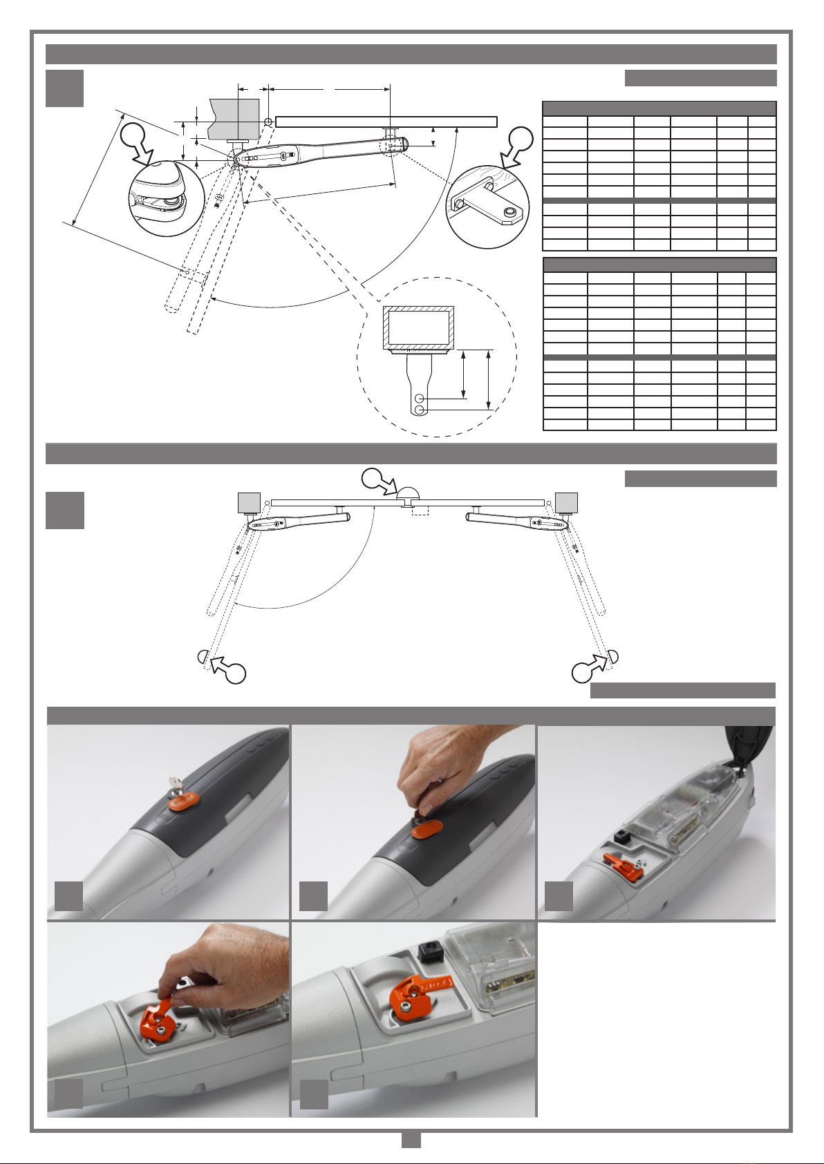
ATTENZIONE! Installare sempre la battuta di arresto meccanico
delle ante (g. 5 pos. 1,2,3).
È responsabilità dell’installatore vericare le seguenti condizioni di sicurezza:
1) L’installazione deve essere sufcientemente lontana dalla strada in modo da non
costituire pericolo per la circolazione.
2) L’operatore deve essere installato all’interno della proprietà ed il cancello non
deve aprirsi verso l’area pubblica.
3) Il cancello motorizzato è principalmente adibito al passaggio di vetture. Dove
possibile installare per pedoni un ingresso separato.
4) I comandi devono essere posti in vista, ad un'altezza compresa tra 1,5 m e 1,8
m, ma non entro il raggio d’azione del cancello. Inoltre quelli installati all’esterno
devono essere protetti da una sicurezza tale da prevenire
l’uso non autorizzato.
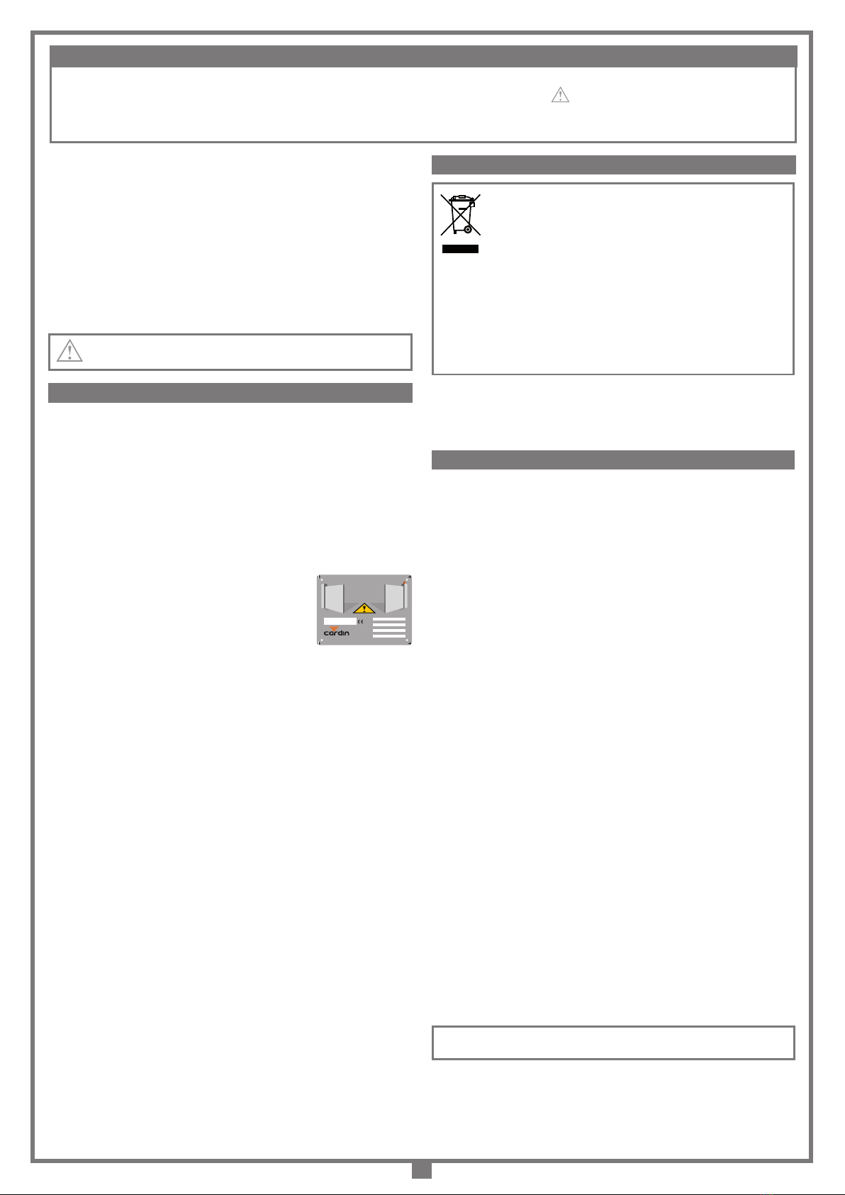
5) È buona norma segnalare l’automazione con targhe di
avvertenza (simili a quella in gura) che devono essere
facilmente visibili. Qualora l’automazione sia adibita al solo
passaggio di veicoli dovranno essere poste due targhe di
avvertenza di divieto di transito pedonale (una all’interno, una all’esterno).
6) Rendere consapevole l’utente che bambini o animali domestici non devono
giocare o sostare nei pressi del cancello. Se necessario indicarlo in targa.
7) Qualora l’anta completamente aperta vada ad avvicinarsi ad una struttura ssa
lasciando uno spazio meno di 500 mm, tale spazio deve essere protetto con una
costa sensibile antischiacciamento.
8) È buona norma proteggere gli accessi laterali del sistema con coppie di fotocellule
collegate all'ingresso di stop (FS), vedi l'esempio d'installazione, componente 14
a pagina 2.
9) Per qualsiasi dubbio a riguardo alla sicurezza dell’installazione, non procedere
ma rivolgersi al distributore del prodotto.
DESCRIZIONE TECNICA
BLEGOS Attuatore elettromeccanico autobloccante con motore a 24 Vdc
per ante no a 2,5 m, 200 kg di peso per anta.
BLESOL Attuatore elettromeccanico autobloccante con motore a 24 Vdc per
ante no a 3,5 m, 300 kg di peso per anta (no a 4 m, 300 kg con l'aggiunta
di una elettroserratura per garantire il blocco dell'anta in chiusura).
• Motore alimentato con tensione max. 28 Vdc con encoder incorporato.
• Riduttore autobloccante su contenitore stagno in AL pressofuso, all'interno
del quale opera un treno di ingranaggi connesso a vite senza ne in acciaio,
la rotazione della quale è supportata da un sistema a doppio cuscinetto.
• Il sistema di sblocco che garantisce le manovre di emergenza è estremamente
efciente in tutte le condizioni ed è protetto da un solido carter in materiale
plastico antiurto con chiusura a chiave.
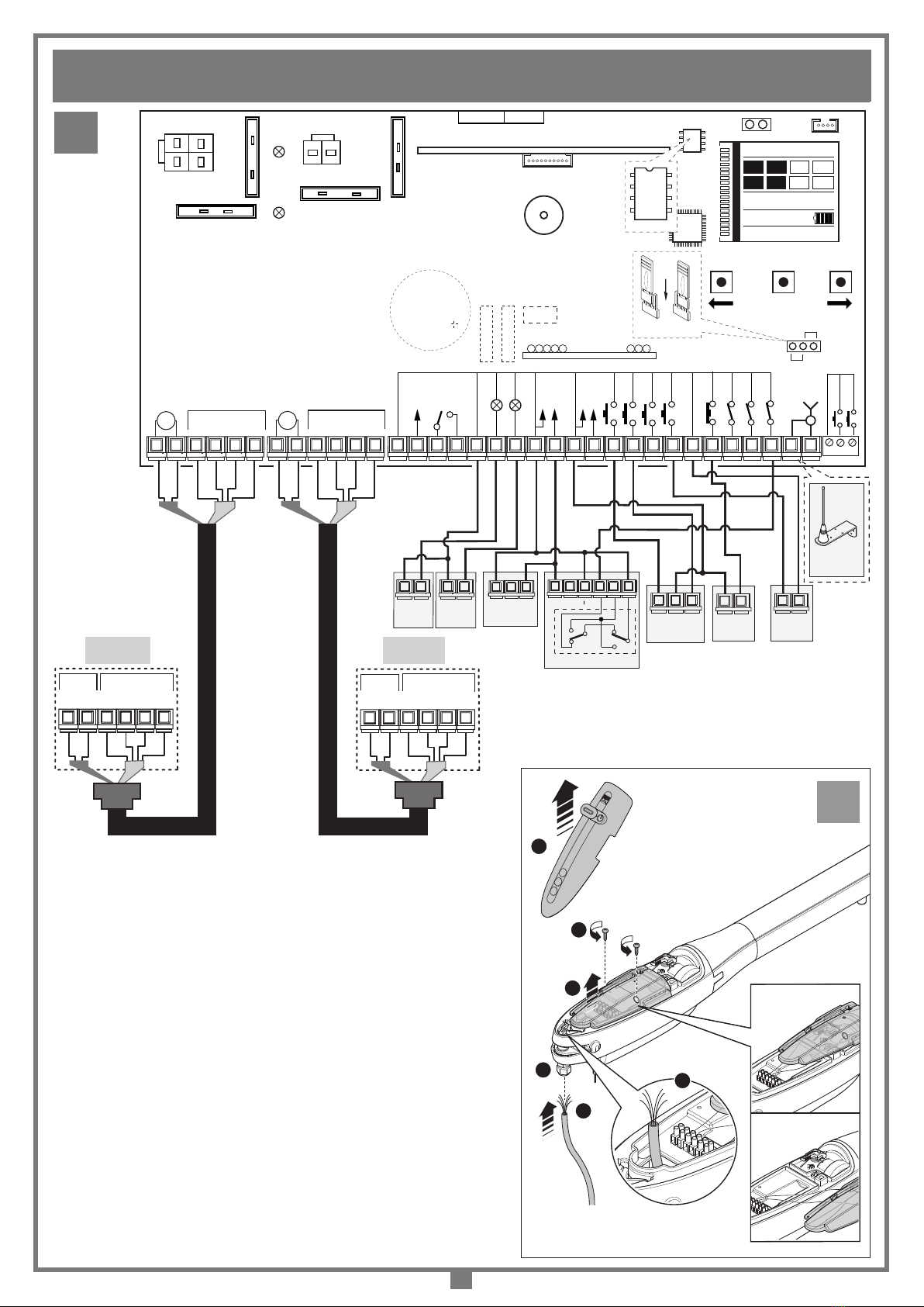
• Vano morsettiera per il cablaggio con cavo Cardin CABPC10 dotato di
coperchio di protezione e pressacavo incorporato.
• Finitura dei componenti di copertura in alluminio verniciato a polveri.
• Staffe e particolari d'aggancio in acciaio zincato.
Attenzione! Solo per clienti dell’EU - Marcatura WEEE.
Il simbolo indica che il prodotto alla ne della propria vita utile deve
essere raccolto separatamente dagli altri riuti. L’utente dovrà
pertanto conferire l’apparecchiatura agli idonei centri di raccolta
differenziata dei riuti elettronici ed elettrici, oppure riconsegnarla al
rivenditore al momento dell’acquisto di una nuova apparecchiatura
di tipo equivalente, in ragione di uno a uno.
L’adeguata raccolta differenziata per l’avvio al riciclaggio, al trattamento e allo
smaltimento ambientalmente compatibile contribuisce ad evitare possibili
effetti negativi sull’ambiente e sulla salute e favorisce il riciclo dei materiali. Lo
smaltimento abusivo del prodotto da parte del detentore comporta l’applicazione
delle sanzioni amministrative previste dalla normativa vigente nello Stato
Comunitario di appartenenza.
Durante la manovra si deve controllare il movimento del cancello e azionare
il dispositivo di arresto immediato (STOP) in caso di pericolo. In caso di
emergenza il cancello può essere sbloccato manualmente utilizzando
l'apposita chiave di sblocco in dotazione (vedi sblocco manuale pag. 4).
I comandi minimi che possono essere installati sono APERTURA-STOP-
CHIUSURA, tali comandi devono essere posti in un luogo non accessibile a
bambini o minori e fuori dal raggio d’azione del cancello.
Prima di procedere all'esecuzione dell'impianto vericare che la struttura da
automatizzare sia in perfetta efcienza nelle sue parti sse e mobili e realizzata
in conformità alla normativa vigente.
A tal ne accertarsi della sufciente rigidità del telo cancello (se necessario
intervenire con rinforzi sulla struttura) e del buon funzionamento dei perni (si
consiglia comunque di lubricare tutte le parti in movimento usando lubricanti
che mantengano uguali caratteristiche di attrito nel tempo e adatti a funzionare
tra -20 e +70°C).
• Controllare i franchi di sicurezza tra parti sse e parti mobili:
- lasciare uno spazio di 30 mm min. tra il cancello ed il pilastro di supporto
per tutta l’altezza e per tutto l’arco di apertura del cancello;
- assicurarsi che lo spazio tra il cancello ed il pavimento non superi mai 30
mm per tutto l’arco di apertura del cancello.
• La supercie delle ante non deve presentare aperture tali da permettere il
passaggio della mano o del piede di persone.
• Controllare l'esatto posizionamento di perni e cerniere, il loro buon stato di
mantenimento e lubricazione (importante che la cerniera superiore e quella
inferiore siano a piombo tra loro).
• Prevedere il percorso dei cavi secondo le necessità di applicazione dei
dispositivi di comando e sicurezza. (ved. impianto tipo).
• Controllare che l’operatore sia proporzionato alle dimensioni del cancello e
alla frequenza d’uso (intermittenza di lavoro, pag. 20).
PROCEDURA DI MONTAGGIO
Il dispositivo può essere ssato sia alla sinistra che alla destra della luce
passaggio.
• Portare l'anta/e in posizione di chiuso.
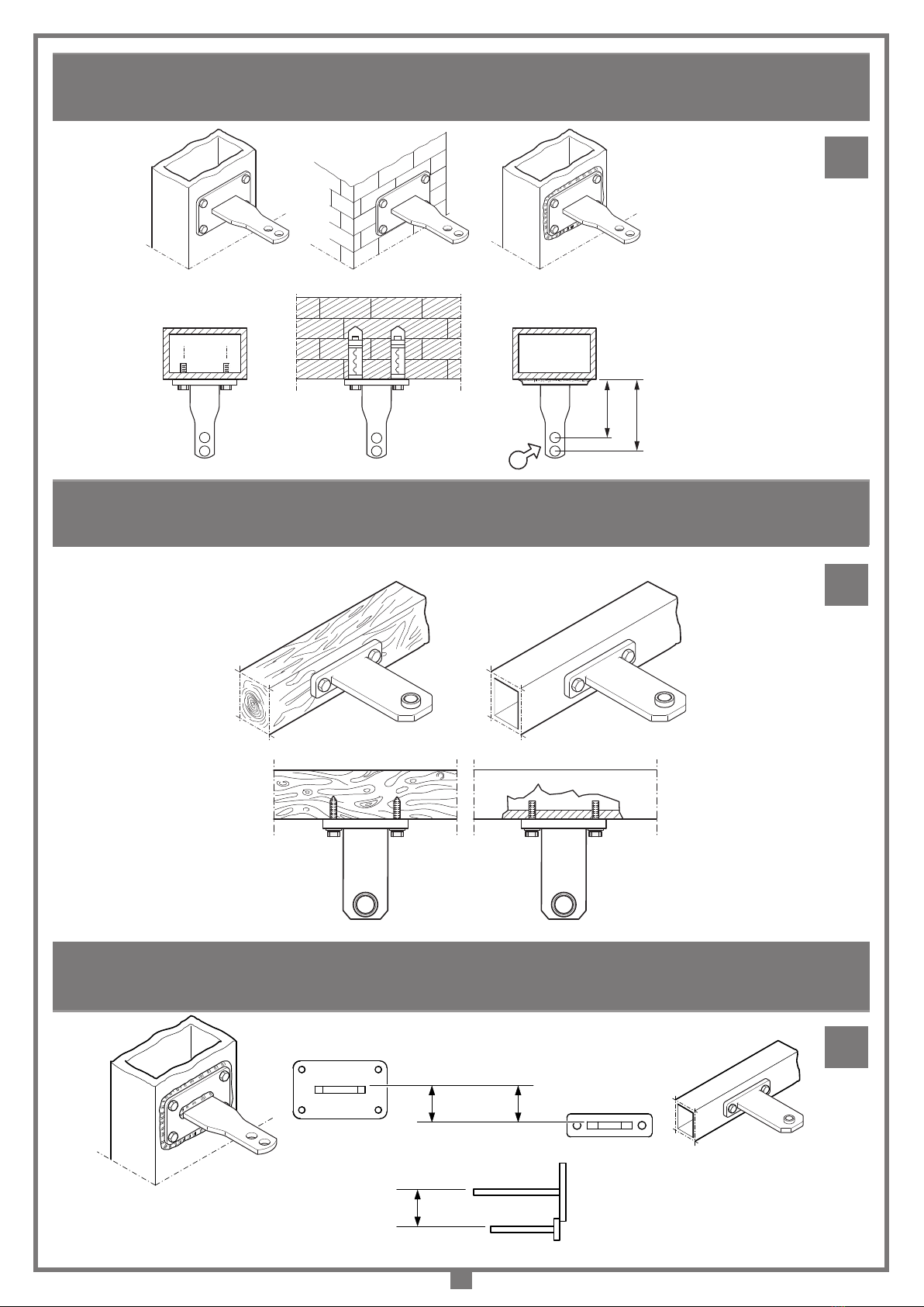
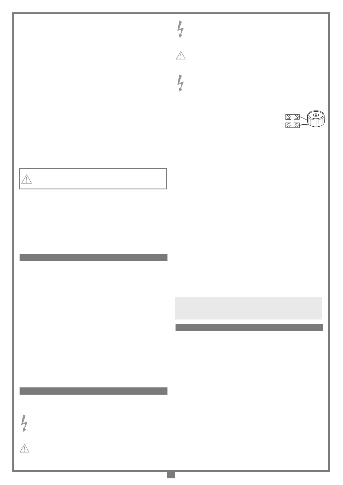
• Fissare al pilastro la staffa posteriore completa fornita con la boccola
inserita (g. 7 pag. 5) , rispettando le quote 'A' e 'B' (g. 4 pag. 4), dopo
aver vericato la posizione della cerniera cancello rispetto al pilastro (quota
'C' g. 4 pag. 4) e in base al tipo di apertura d'anta da effettuare.
Nota: in caso di preinstallazione delle staffe (posteriore ed anteriore)
senza la presenza del pistone, consultare anche le indicazioni in gura 9.
• Slare il carter di protezione dalla vite (tutto il sistema vite, chiocciola, fermi
regolabile di sicurezza risulterà esposto)
• Far traslare la chiocciola dell'attuatore (part. 8 g. 2) no ad arrivare a 15 mm
dal completamento della corsa in chiusura e portare ruotandoli in posizione
ottimale le battute meccaniche '5' e '9' (g. 2) situate sulla vite.
ATTENZIONE! IMPORTANTI ISTRUZIONI DI SICUREZZA
CONSIDERAZIONI GENERALI DI SICUREZZA
AVVERTENZE PER L'UTENTE
ISTRUZIONI PER L'INSTALLAZIONE
È IMPORTANTE PER LA SICUREZZA DELLE PERSONE SEGUIRE QUESTE ISTRUZIONI: LEGGERE ATTENTAMENTE LE SEGUENTI AVVERTENZE PRIMA DI
PROCEDERE ALL’INSTALLAZIONE. PRESTARE PARTICOLARE ATTENZIONE A TUTTE LE SEGNALAZIONI DISPOSTE NEL TESTO DI QUESTO LIBRETTO
D’ISTRUZIONI ORIGINALE. IL MANCATO RISPETTO DI QUESTE POTREBBE COMPROMETTERE IL BUON FUNZIONAMENTO DEL SISTEMA E CREARE SITUAZIONI
DI PERICOLO GRAVE PER L’OPERATORE E GLI UTILIZZATORI DEL SISTEMA STESSO. CONSERVARE QUESTE ISTRUZIONI PER OGNI FUTURO RIFERIMENTO.
ZVE:572 - Mod: 04-09-2017
riello elettronica group
®
AUTOMATIC OPENING
APERTURA AUTOMATICA
FERMETURE AUTOMATISÉE
AUTOMATISCHER ÖFFNUNG
Serial number:Installation company:
Product model:
Installation date:
Weight in kg:

8
• Il cavo di alimentazione deve essere in gomma e del tipo 60245 IEC
57 (es. 3 x 1.5 mm2 H05RN-F).
• La sostituzione del cavo d’alimentazione deve essere eseguita da
personale qualicato.
• Tra la centralina di comando e la rete deve essere interposto un
interruttore onnipolare, con distanza di apertura tra i contatti di almeno
3 mm.
• Non utilizzare cavo con conduttori in alluminio; non stagnare
l’estremità dei cavi da inserire in morsettiera; utilizzare cavo con
marcatura T min 85°C resistente agli agenti atmosferici.
• I conduttori dovranno essere adeguatamente ssati in prossimità
della morsettiera in modo che tale ssaggio serri sia l’isolamento
che il conduttore.
COLLEGAMENTI ALIMENTAZIONE CENTRALINA 230 Vac
• Collegare i li di comando e quelli provenienti dalle sicurezze.
• Portare l'alimentazione generale al programmatore
collegandolo alla morsettiera a due vie che è già
collegata al primario del trasformatore.
PREPARAZIONE CAVO COLLEGAMENTO MOTORE (g 10-11)
• Il kit contiene 10 metri di cavo a sei poli da tagliare secondo le esigenze
dell'impianto.
• Portare il cavo di collegamento all’apparecchiatura:
- ruotare la protezione della serratura, inserire la chiave e girarla di 180 gradi
in senso orario;
- togliere la copertura '1';
- Svitare i viti '2' e togliere il coperchio a protezione LED '3' prestando
attenzione a non tirare troppo il cavo LED. La posizione ideale e marcato
'ok' in gura.
• Far passare il cavo '4' attraverso il pressocavo '5'.
• Collegare i li del motore 'M1' e l'encoder '1' sulla morsettiera a sei vie '6'.
• Rispettare scrupolosamente la sequenza di connessione dei motori alla
centralina; l’ordine dei morsetti 1...6 è identico sul motore e sulla centralina.
Motore 1
1-2 Alimentazione motore 1
3-4-5-6 Ingressi per segnali encoder 1
Motore 2
1-2 Alimentazione motore 2
3-4-5-6 Ingressi per segnali encoder 2
• Serrare a fondo il tappo del pressacavo '5', rimettere il coperchio a
protezione LED '3', riposizionare la copertura '1' e chiuderla a chiave.
• Ripetere l'operazione per il secondo motore ed il secondo encoder.
Programmatore elettronica
Per laprogrammazione elettronica e funzionalitàa batteria consultare illibretto
d’istruzioni MULTI-ECU SOFTWARE ZVL608 fornito con l’automazione.
Per usufruire della garanzia di 24 mesi o di 50000 manovre leggere attentamente
le seguenti note.
Attenzione! Prima di eseguire qualsiasi operazione di pulizia o di manutenzione,
disinserire l’apparecchiatura dalla rete di alimentazione elettrica, staccare
l’alimentazione del motore e scollegare le batterie.
Le eventuali riparazioni devono essere eseguite da personale specializzato usando
materiali originali e certicati.
Il motore normalmente non necessita di particolari manutenzioni; in ogni caso
la garanzia fornita per 24 mesi o di 50000 manovre ha validità a condizione
che vengono effettuati i seguenti controlli ed eventuali interventi sulla macchina
‘
cancello a battente
’:
- controllare periodicamente lo stato di usura dei perni ed eventualmente
ingrassare le parti in moto in particolare la vite pos. 7 g. 2, usando
lubricanti che mantengano uguali caratteristiche di attrito nel tempo e
adatti a funzionare tra -20 e +70°C;
- vericare periodicamente il funzionamento delle sicurezze (fotocellule, coste
sensibili ecc.);
- vericare il livello di carica delle batterie.
Dette veriche devono essere documentate in quanto sono indispensabili per
usufruire della garanzia.
• Fissare con l'apposito perno '1' l'attuatore alla staffa di coda '4' (g. 2).
• Portare l'attuatore nella normale posizione di funzionamento appoggiando
al cancello la staffa di testa '11', contrassegnandone poi la posizione.
Nota: Posizionare l'operatore perfettamente orizzontale vericandone l'esatta
posizione usando una livella a bolla d'aria.
• Fissare la staffa di ssaggio anteriore (g. 8, pag. 5).
• La staffa va ssata nei seguenti punti:
- nella struttura portante del cancello o nel fascione trasversale del cancello;
- nel caso mancassero queste possibilità è preferibile ssare al cancello una
piastra aggiuntiva che servirà poi da piastra di supporto.
• Inserire il perno della chiocciola '8' nell'apposito foro della staffa '11' e
bloccare con la rondella e vite M6 (g. 2, pag. 3).
• Sbloccare l'attuatore e portare l'anta in apertura e verificare l'esatto
funzionamento di tutti gli elementi.
• Individuate le posizioni di chiusura e apertura portare in posizione le battute
meccaniche sulla vite e bloccarle stringendo a fondo le apposite viti e il
grano di ssaggio. Le battute meccaniche garantiscono una posizione
certa di finecorsa per il funzionamento dell'attuatore consentendo
l'autoprogrammazione del sistema. Per tanto vericarne la perfetta posizione
in base all'apertura desiderata e il perfetto bloccaggio sulla vite.
• Compiere alcune manovre di verica attuando il movimento manuale.
• Completare i collegamenti elettrici (vedi programmatore elettronico).
• Ribloccare e compiere alcune manovre in automatico.
• Inlare il carter di protezione '6' nella sua sede e ssarlo sul riduttore con le
2 viti M6 ('13' g 2).
ATTENZIONE: Accertarsi che ad attuatore installato, la protezione
antipolvere sia rivolta verso l’interno del carter (come indicato in
gura 2a) e non verso l’esterno.
• Accertarsi che il portello di copertura sblocco sia chiuso e ritirare la chiave
conservandola in luogo sicuro e di facile reperimento.
• Per l'attuatore BLESOL utilizzando un'anta superiore a 3,5 m no a 4 m
sarà necessaria l'applicazione di un'elettroserratura di blocco per garantire
il blocco dell'anta in chiusura.
Importante! Il modello è provvisto di battute meccaniche registrabili '5' (anta
aperto) e '9' (anta chiusa). Installare e portare le battute meccaniche '5' e '9'
ognuna nel punto più opportuno di apertura e di chiusura, quindi bloccare
ciascuna battute con le viti, dadi e grani in dotazione.
L'operazione di sblocco va eseguita solamente a motore fermo al ne di attuare
la manovra di emergenza in caso di assenza di tensione di rete.
Per sbloccare l'anta del cancello munirsi della chiave in dotazione
all'apparecchiatura. Essa deve essere conservata in luogo sicuro e di facile
reperimento.
Per sbloccare:
a) rotare la protezione della serratura;
b) inserire la chiave di sblocco e girarla 180 gradi in senso orario;
c) togliere la copertura dello sblocco;
d) far ruotare la levetta arancione dello sblocco 90 gradi in senso orario;
e) In questa posizione il sistema è sbloccato ed il cancello può essere
manovrato manualmente,
- nel caso si voglia mantenere sbloccato il motore, chiudere la copertura.
Per ribloccare:
- eseguire le operazioni da 'e' ad 'a' e togliere la chiave.
Nota: Per facilitare l'operazione di riarmo se necessario muovere leggermente
l'anta. Non forzare, se si dovessero trovare punti duri spostare leggermente
il cancello dalla posizione in modo da facilitare l'operazione di riaggancio dei
denti delle ruote dentate all'interno del riduttore.
Avvertenze importanti
• Dopo aver installato il dispositivo, e prima di dare tensione alla
centralina, vericare che il movimento del cancello eseguito in
modo manuale (con motore sbloccato) non abbia punti di resistenza
particolarmente marcata.
• La presenza del sensore di corrente non elimina l’obbligo di installare le
fotocelluleo altri dispositividisicurezzaprevistidallenormativevigenti.
• Accertarsi, prima di eseguire il collegamento elettrico, che la tensione
e la frequenza riportate sulla targhetta caratteristiche corrispondano a
quelle dell’impianto di alimentazione.
SBLOCCO MANUALE (fig. 6)
N
L
MANUTENZIONE
COLLEGAMENTO ELETTRICO

9
• These instructions are aimed at professionally qualied ‘INSTALLERS OF
ELECTRICAL EQUIPMENT’ and must respect the local standards and
regulations in force.
All materials used must be approved and must suit the environment in
which the installation is situated and all maintenance operations must be
carried out by professionally qualied technicians.
• This appliance must be used exclusively for the purpose for which it has
been made. ‘i.e. for the automation of hinged gates’ with one or two
gate leaves.
CAUTION! Mechanical stop buffers must be installed in both the
closing and opening positions. (pos. 1, 2 and 3, g. 5).
It is the responsibility of the installer to make sure that the following public safety
conditions are satised:
1) Ensure that the gate operating installation is far enough away from the main road
to eliminate possible trafc disruptions.
2) The motor must be installed on the inside of the property and not on the public
side of the gate. The gates must not open onto a public area.
3) The gate operator is designed for use on gates through which vehicles are passing.
Pedestrians should use a separate entrance.
4) Thecontrolsmustbeinstalled ataheightbetween1,5and1,8 mandinalocation
not accessible to children. Controls installed externally must be protected by
a safety device inhibiting unauthorised use.
5) At least two warning signs (similar to the example on the
right) should be placed, where they can be easily seen
by the public, in the area of the system of automatic
operation. One inside the property and one on the public
side of the installation. These signs must be indelible and not hidden by any
objects (such as tree branches, decorative fencing etc.).
6) Make sure that the end-user is aware that children and/or pets must not be allowed
to play within the area of a gate installation. If possible include this in the warning
signs.
7) Whenever a fully open gate leaf comes within at 500 mm of a xed structure the
space must be protected by an anticrush buffer.
8) You are advised to protect the system’s lateral access points with pairs of (FS)
photocells connected to the stop input, see installation example, component 14
on page 2.
9) If you have any questions about the safety of the gate operating system, do not
install the operator. Contact your dealer for assistance.
TECHNICAL DESCRIPTION
BLEGOS Self-locking electromechanical 24 Vdc ram suitable for hinged gates
up to 2,5 m in length and 200 kg in weight (per gate leaf).
BLESOL Self-locking electromechanical 24 Vdc ram suitable for hinged gates
up to 3,5 m in length and 300 kg in weight per gate leaf (up to 4 m, 300 kg
addition of an electric locking device).
• Drive motor maximum 28 Vdc with an incorporated encoder
• Self-locking geared motor with a watertight container in extruded aluminium
containing cyclic train gears. Rotation is supported by a system of double
bearings.
• The release mechanism that guarantees emergency manoeuvring is
extremely efcient under all working conditions and is protected by a solid
shock-proof plastic carter with a key lock.
• The terminal board (wired up using Cardin cable CABPC10) is located in a
special compartment tted with a cable clamp and a protective cover.
• The covering components are nished in spray painted aluminium.
• Brackets and accessories in zinc-plated steel.
Attention! Only for EU customers - WEEE marking.
This symbol indicates that once the products life-span has
expired it must be disposed of separately from other rubbish. The
user is therefore obliged to either take the product to a suitable
differential collection site for electronic and electrical goods or
to send it back to the manufacturer if the intention is to replace
it with a new equivalent version of the same product.
Suitable differential collection, environmental friendly treatment and disposal
contributes to avoiding negative effects on the ambient and consequently
health as well as favouring the recycling of materials. Illicitly disposing of this
product by the owner is punishable by law and will be dealt with according
to the laws and standards of the individual member nation.
During the opening/closing manoeuvre check for correct operation and activate
the emergency stop button in case of danger. During blackouts the gate can
be released and manually manoeuvred using the supplied release key (see
manual release page 4).
The minimum controls which may be installed are OPEN-STOP-CLOSE, these
controls must be installed in a location not accessible to children and outside
the opening range of the gate.
Before starting the installation of the system check that the structure which
is to be automated is in good working order and respects the local standards
and regulations in force.
To this end make sure that the gate is sufciently rigid (if necessary reinforce
the structure) and that it pivots easily.
You are advised to grease all the moving parts using lubricants which maintain
unaltered friction characteristics over a period of time and are suitable for
temperatures of -20 to +70°C.
• Check the safety measures between the xed and moving parts:
- a minimum space of 30 mm must always be left along the entire distance
between the gate and the support column measured throughout the entire
opening angle of the gate.
- make sure that the space between the bottom of the gate and the pavement
never exceeds 30 mm throughout the entire opening angle of the gate.
• The surface of the gate must not feature openings which allow a person’s
hand or foot to pass through.
• Check the exact positioning of the pivots, and their good working order (the
upper and lower hinges/pivots must be aligned on the same axis).
• Work out the run of the cables according to the command and control
devices tted and make sure the system conforms to the local standard
and regulations in force (see installation example).
• Check that the appliance is suitable for the size, weight and duty cycle of
the gate to which it is to be applied (see duty cycle on page 20).
ASSEMBLY PROCEDURE
The ram may be positioned to the right or to the left of the passageway.
• Move the gate/s to the closed position.
• Fasten the rear mooring bracket (supplied with a ferrule inserted) to the
column (g. 7 page 5), taking into account the measurements ‘A’ and ‘B’,
after having checked the position of the gate hinge with respect to the
column (measurement ‘C’ g. 4 page 4) according to the type of opening
required.
Note: if the gate brackets are to be pre-installed (front and rear) without
the presence of the ram, you must also consult the indications in gure 9.
•
Slide off the worm screw protective cover (the screw, lead nut and
adjustable safety rings will now be exposed)
• Rotate the worm screw lead nut (part. 8 g. 2) until it reaches 15 mm from
the end of the closing direction travel distance and rotate the mechanical
travel limits ‘5’ and ‘9’ along the screw to their optimum position.
ATTENTION! IMPORTANT SAFETY INSTRUCTIONS
IMPORTANT SAFETY INSTRUCTIONS
USER INSTRUCTIONS
INSTALLATION INSTRUCTIONS
READING THESE INSTRUCTIONS IS IMPORTANT FOR PERSONAL SAFETY. READ THE FOLLOWING REMARKS CAREFULLY BEFORE
PROCEEDING WITH THE INSTALLATION. PAY PARTICULAR ATTENTION TO ALL THE PARAGRAPHS MARKED WITH THE SYMBOL IN THIS
ORIGINAL INSTRUCTION MANUAL. NOT READING THESE IMPORTANT INSTRUCTIONS COULD COMPROMISE THE CORRECT WORKING ORDER
OF THE SYSTEM AND CREATE DANGER SITUATIONS FOR THE USERS OF THE SYSTEM. SAVE THESE INSTRUCTIONS FOR FUTURE USE.
ZVE:572 - Mod: 04-09-2017
riello elettronica group
®
AUTOMATIC OPENING
APERTURA AUTOMATICA
FERMETURE AUTOMATISÉE
AUTOMATISCHER ÖFFNUNG
Serial number:Installation company:
Product model:
Installation date:
Weight in kg:

10
• The motor’s power cable must be made of polychloroprene in
conformity with the international standard 60245 IEC 57 (e.g. 3 x 1.5
mm2H05RN-F).
• The cable may only be replaced by qualied technicians.
• An all pole trip switch with at least 3 mm between the contacts must
be installed between the unit and the mains supply.
• Don’t use cables with aluminium conductors; don’t solder the ends
of cables which are to be inserted into the binding posts; use cables
marked T min 85°C and resistant to atmospheric agents.
• The terminal wires must be positioned in such a way that both the
wire and the insulating sheath are tightly fastened.
POWER SUPPLY CONNECTION 230 Vac
• Connect the control and security device wires
• Run the mains power supply to the programmer
and connect it to the separate two-way terminal
board that is already connected to the transformer.
PREPARING THE MOTOR CONNECTION WIRES (g 10-11)
•
The kit contains 10 metres of 6-wire cable that should be cut according to
the needs of the installation.
• Run the power cable to the appliance.
- rotate up the key protection cover, insert the release key and rotate it
180 degrees clockwise;
- remove the cover ‘1’;
- unscrew the screws ‘2’ and remove the LED protection cover ‘3’ making
sure that you do not overstretch the LED cable. The ideal position is
marked ‘ok’ in the drawing;
- pass the cable ‘4’ through the cable clamp ‘5’.
• Connect the wires of motor ‘M1’ and encoder ‘1’ to the electronic
programmer six-way terminal board.
• You must scrupulously respect the motor connection sequence between
the motors and the programmer. The order of the binding post connections
1 to 6 is identical on both.
Motor 1
1-2
Motor power supply
1
3-4-5-6
Encoder signal input
1
Motor 2
1-2
Motor power supply
2
3-4-5-6
Encoder signal input
2
• Fasten down the cable clamp ‘2’; replace the LED protection cover ‘3’,
reposition the cover ‘1’and lock it.
• Repeat the operation for the second motor and the second encoder.
Electronic programming unit
Instructions for programming the ECU and battery powered operation can be found
in the MULTI-ECU SOFTWARE manual ZVL608 supplied with the automation.
To use the 24 month or 50000 manoeuvre guarantee, read the following notes
carefully.
Attention! Before carrying out any cleaning or maintenance operations make
sure the power is disconnected at the mains, the motor power cables are
disconnected and the batteries have been disconnected.
Eventual repair work must be carried out by specialised personnel using original
spare parts.
The motor does not normally require particular maintenance; in any case the 24
month or 50000 manoeuvre guarantee is only valid if the following controls have
been observed and eventual maintenance has been carried out to the machine
‘hinged gate’:
-
periodically check the moving parts for wear and tear and grease if required,
paying particular attention to the never ending screw pos. 7 g. 2, using
lubricants which maintain their friction levels unaltered throughout time and
are suitable for temperatures of -20 to +70°C.
-
periodically check the correct operation of all safety devices (photoelectric
cells, safety edges
etc.);
- check the battery charge level.
These checks must be written down as they are paramount in validating the
guarantee.
•
Fix the ram to the rear mooring bracket ‘4’ (g. 2 page 3).
• Move the ram to its normal operating position, rest the head against the
gate and mark the position of the front bracket ‘11’.
Note: Make sure the operator is perfectly level (using a spirit level).
• position the front holding bracket (g. 8 page 5).
• The front bracket may be xed in the following positions:
- on the gate frame or on a horizontal cross beam;
- if this is not possible, x a reinforcing plate to the gate structure and then
fasten the front bracket onto the reinforcing plate.
• Insert the retaining pin of the worm screw ‘8’ into the front bracket ‘1’ and
fasten down using the supplied washer and M6 screw (g. 2 page 3).
• With the motor released move it manually to the fully open position and
check that all the components work correctly.
• Once you have located the opening and closing points, position the
mechanical travel limits and tighten them down using the hexagonal and
grub screws. This will guarantee a secure position for the travel limit and
allow the automatic repositioning function to work correctly. Therefore
make sure the position is correct with respect to the opening position and
that the screws are well fastened down.
• Carry out a series of checks moving the gate manually.
• Carry out the electrical connection (see ‘Electronic programmer’).
• Slide the protective cover ‘6’ over the worm screw and fasten it to the
reduction unit using the two M6 screws (‘13’ g. 2).
WARNING:
make sure that once you have installed the ram the
anti-dust protective sheaths are pointing towards the inside of the
drive rod cover (as shown in gure 2a ) and not towards the outside.
•
Make sure that the manual release mechanism cover is closed, remove the
key and store it in a safe and easily reachable place.
•
With the BLESOL and a gate larger than 3,5 m to 4 m in width, an electric
locking device must be tted to ensure that the gate is blocked when it is
closed.
Important!
The model is tted with adjustable mechanical travel limits ‘5’ (gate
open) and ‘9’ (gate closed). Install and move the travel limits ‘5’ and ‘9’ to the
desired opening and closing positions then tighten them carefully using the
supplied screws, nuts and grub screws.
Releasing the gate should only be carried out when the motor has stopped
so that the gate can be manoeuvred manually during blackouts.
To release the gate use the key supplied with the appliance. It should be
stored in a safe and easily reachable place.
To release the gears:
a) rotate up the key protection cover;
b) insert the release key and rotate it 180 degrees clockwise;
c) remove the release mechanism cover;
d) rotate the orange release lever 90 degrees clockwise;
e) in this position the gears are released and the gate can be manoeuvred
manually
- if you wish to leave the gears released, just close the lock cover.
To lock the gears:
- carry out points ‘e’ to ‘a’ and then remove the key.
Note: To make the operation easier the gate can be moved slightly if required.
Don’t force the locking mechanism, if you encounter resistance move the gate
slightly to allow the cogs to slot together more easily within the geared motor.
Important remarks
• After having installed the device, and before powering up the
programmer, release the door (manual release mechanism) and move
it manually, checking that it moves smoothly and has no unusual points
of resistance.
• The presence of the electrical current sensor does not dispense with
the obligation to install photoelectric cells and other safety devices
foreseen by the safety standards in force.
• Before connecting the appliance make sure that the voltage and
frequency rated on the data plate conform to the mains supply.
MANUAL RELEASE MECHANISM (fig. 6)
N
L
MAINTENANCE
ELECTRICAL CONNECTION

11
• Ce livret est destiné à des personnes titulaires d’un certicat d’aptitude
professionnelle pour l’installation des ‘appareils électriques’ et requiert
une bonne connaissance de la technique appliquée professionnellement,
ainsi que des normes en vigueur.
Les matériels utilisés doivent être certiés et être adaptés aux conditions
atmosphériques du lieu d’implantation. Les travaux de maintenance
doivent être effectués par un personnel qualié.
• Les appareils décrits dans le présent livret ne doivent être destinés qu’à
l’utilisation pour laquelle ils ont été expressément conçus, c’est-à-dire à
‘La motorisation de portails battants à un ou deux vantaux’.
ATTENTION!Il est impératif d’installer les butées mécaniques
d’arrêt des vantaux (g. 5, pos. 1, 2 et 3).
Il appartient à l’installateur de vérier les conditions de sécurité ci-dessous:
1) L’installation doit se trouver sufsamment loin de la route pour ne pas
constituer de risque pour la circulation;
2) L’opérateur doit être installé à l’intérieur de la propriété et le portail ne doit
pas s’ouvrir sur le domaine public;
3) Le portail automatisé est affecté principalement au passage de véhicules. Si
possible, prévoir une entrée séparée pour les piétons;
4) Les organes de commande doivent être placés de façon qu’ils soient bien en
vue, à une hauteur oscillant entre 1,5 m et 1,8 m et hors du rayon d’action du
portail. En outre, ceux placés à l’extérieur doivent être protégés de manière
à empêcher toute utilisation non autorisée.
5) Il est conseillé de signaler l’automatisation du portail par des panneaux de
signalisation (comme celui indiqué en gure) placés
bien en vue. Dans l’hypothèse où l’automatisme serait
affecté exclusivement au passage de véhicules, il faudra
prévoir deux panneaux d’interdiction de passage aux
piétons (l’un à l’intérieur et l’autre à l’extérieur);
6) En outre, ceux placés à l’extérieur doivent être protégés
de manière à empêcher toute utilisation non autorisée. Si nécessaire, l’indiquer
sur le panneau;
7) Si le vantail, une fois qu’il est complètement ouvert, se trouve très proche
d’une structure xe, créant un espace de moins de 500 mm, ce dernier devra
être sécurisé par une barre palpeuse anti-coincement.
8) Il est de règle de protéger les accès latéraux du système au moyen de couples
de cellules photoélectriques branchés à l’entrée FS (stop), voir l’exemple
d’installation, composant 14 page 2.
9) En cas d’un quelconque doute sur la sécurité de l’installation, interrompre la
pose et contacter le distributeur du matériel.
DESCRIPTION TECHNIQUE
BLEGOS Opérateur électromécanique 24 Vdc autobloquant pour portails
battants allant jusqu’à 2,5 m par vantail d’un poids maximum de 200 kg.
BLESOL Opérateur électromécanique 24 Vdc autobloquant pour portails
battants allant jusqu’à 3,5 m par vantail d’un poids maximum de 300 kg. Il peut
être appliqué sur portails allant jusqu’à 4 m par vantail d’un poids maximum de
300 kg en ajoutant une serrure électrique pour garantir le verrouillage du portail.
• Moteur alimenté avec une tension maxi. 28 Vdc avec encodeur intégré.
• Réducteur autobloquant sous caisson étanche en AL moulé sous pression.
Il renferme en soi un train d’engrenages raccordé à une vis sans n en acier;
la rotation de celle-ci fait appel à un système à double roulement.
• Le système de déverrouillage, qui permet d’effectuer la manœuvre d’urgence,
est extrêmement efcace en toute condition, et est protégé par un carter
extrêmement robuste en matière plastique antichoc et fermant à clé.
• Logement bornier pour le câblage avec câble Cardin CABPC10, doté de
couvercle et de presse-étoupe incorporé.
• Finition des composants de couverture en aluminium peinture poudre.
• Pattes et éléments de liaison en acier galvanisé.
Attention!Seulement pour les clients de EU - Marquage WEEE.
Ce symbole indique l’obligation de ne pas éliminer l’appareil, à la n de sa
durée de vie, avec les déchets municipaux non triés et de procéder à sa
collecte sélective. Par conséquent, l’utilisateur doit remettre l’appareil à
un centre de collecte sélective des déchets électroniques et électriques
ou au revendeur qui est tenu, lorsqu’il fournit un nouvel appareil, de faire
en sorte que les déchets puissent lui être remis, sur une base de un pour
un, pour autant que l’appareil soit de type équivalent à celui qu’il fournit.
La collecte sélective des équipements électriques et électroniques en vue de leur
valorisation, leur traitement et leur élimination dans le respect de l’environnement
contribue à éviter la nocivité desdits équipements pour l’environnement et pour
la santé et à encourager leur recyclage. L’élimination abusive de l’équipement
de la part du détenteur nal comporte l’application des sanctions administratives
prévues par les normes en vigueur dans l’État Membre d’appartenance.
Durant la manœuvre, contrôler le mouvement du portail et actionner, en cas de
danger, le dispositif d’arrêt d’urgence (STOP).
En cas d’urgence, le portail peut être déverrouillé manuellement au moyen de
la clé de déverrouillage expressément conçue à cet effet et fournie en dotation
(voir déverrouillage manuel à la page 4).
L’organe de commande minimum requis est une boîte à boutons OUVERTURE-
STOP-FERMETURE; celle-ci devra être installée impérativement hors de portée
de mineurs, notamment des enfants, et hors du rayon d’action du portail.
Avant de réaliser l’installation, s’assurer de l’efcacité des parties xes et mobiles
de la structure à automatiser et de la conformité de celle-ci aux normes en vigueur.
Dans cet objectif, s’assurer de la rigidité du tablier du portail (si nécessaire renforcer
la structure) et du bon fonctionnement des pivots (il est conseillé de graisser
toutes les parties mobiles avec un lubriant qui maintient au l des années les
caractéristiques de friction et qui est adapté à des températures oscillant entre
-20° et +70°C).
• Respecter les jeux fonctionnels entre parties xes et mobiles:
- laisser un espace de 30 mm min. entre le portail et le pilier de support sur
toute la hauteur et sur la totalité de l’arc d’ouverture du portail,
- contrôler que l’espace entre le portail et le sol ne soit jamais supérieur à 30
mm sur la totalité de l’arc d’ouverture du portail.
• Lespanneauxdesvantauxnedoivent pasprésenterd’ouverturesquipermettent
le passage de la main ou du pied.
• Contrôler l’emplacement correct des pentures et des gonds, leur bon état et
leur lubrication (il est important que les gonds supérieur et inférieur soient en
aplomb l’un par rapport à l’autre).
• Prévoir une gaine pour le passage des câbles électriques en fonction des
dispositifs de commande et de sécurité (voir exemple d’installation).
• Contrôler que l’opérateur soit proportionné aux dimensions du portail et à la
fréquence d’utilisation (facteur de marche page 20).
MONTAGE
Le dispositif peut être monté aussi bien à gauche qu’à droite du passage. .
• Fermer le vantail ou les vantaux.
• Fixer la patte postérieure, fournie avec douille insérée, au pilier (g.7 page
5) en respectant les cotes ‘A’ et ‘B’ (g. 4 page 4), après avoir contrôlé
la position de la penture du portail par rapport au pilier (cote ‘C’ g. 4
page 4) et en fonction du type d’ouverture à réaliser.
Remarque: en cas de pré-montage des pattes (postérieure et antérieure)
sans la présence du piston, voir également les indications en gure 9.
• Retirer le carter de la vis (tout le système vis, noix et butées de sécurité
réglables s’avérera à ce point découvert).
• Déplacer la noix de l’opérateur (dét. 8 g. 2) de façon à la faire arriver à 15
mm de la n de la course en fermeture et placer les butées mécaniques ‘5’ et
‘9’ (g. 2) situées sur la vis, en les faisant tourner, dans une position optimale.
• Assembler l’opérateur à la patte postérieure ‘4’ au moyen de l’axe ‘1’ (g.
2 page 3).
ATTENTION! CONSIGNES DE SÉCURITÉ IMPORTANTES
CONSIGNES GÉNÉRALES DE SÉCURITÉ
CONSIGNES POUR L’UTILISATEUR
INSTRUCTIONS POUR L’INSTALLATION
IL EST IMPORTANT POUR LA SÉCURITÉ DES PERSONNES D’OBSERVER LES INSTRUCTIONS SUIVANTES: LIRE ATTENTIVEMENT LES
CONSIGNES SUIVANTES AVANT DE PROCÉDER AU MONTAGE. PORTER UNE ATTENTION PARTICULIÈRE À TOUTES LES CONSIGNES MISES
EN ÉVIDENCE PAR LES PICTOGRAMMES FIGURANT DANS LE PRÉSENT LIVRET D’INSTRUCTIONS ORIGINAL. LE NON-RESPECT DE
CES CONSIGNES POURRAIT COMPROMETTRE LE BON FONCTIONNEMENT DU SYSTÈME ET CRÉER DES SITUATIONS DE GRAVE DANGER
POUR L’OPÉRATEUR ET LES UTILISATEURS DU SYSTÈME. CONSERVER CETTE NOTICE POUR POUVOIR LA CONSULTER ULTÉRIEUREMENT.
ZVE:572 - Mod: 04-09-2017
riello elettronica group
®
AUTOMATIC OPENING
APERTURA AUTOMATICA
FERMETURE AUTOMATISÉE
AUTOMATISCHER ÖFFNUNG
Serial number:Installation company:
Product model:
Installation date:
Weight in kg:

12
• Le câble d’alimentation doit être en caoutchouc et du type 60245
IEC 57 (ex. 3 x 1.5 mm
2
H05RN-F).
• Le remplacement du câble d’alimentation doit être effectué par un
personnel qualié.
• Entre la centrale de commande et le réseau doit être interposé un
interrupteur omnipolaire avec ouverture des contacts d’au moins
3 mm.
• Ne pas utiliser de câble avec des conducteurs en aluminium; ne pas
étamerl’extrémitédes câbles à insérerdans le bornier;utiliseruncâble
marqué T min. 85°C résistant à l’action des agents atmosphériques.
• Les conducteurs devront être xés à proximité du bornier de
manière telle que la xation maintiennent aussi bien l’isolation que
le conducteur.
BRANCHEMENT DE L’ALIMENTATION DE LA CENTRALE 230 Vac
• Brancher les ls de commande et ceux qui
proviennent des dispositifs de sécurité.
• Tirer le câble d’alimentation générale jusqu’au
programmateur et le brancher au bornier à deux voies qui est déjà relié
au primaire du transformateur.
PRÉPARATION DU CÂBLE DE BRANCHEMENT DU MOTEUR
(g 10-11)
• Le kit contient un câble de 10 m à six pôles à couper selon les particularités
de l’installation.
• Tirer le câble de branchement jusqu’à l’appareil:
- pivoter la protection de la serrure, engager la clé et la tourner de 180 degrés
dans le sens des aiguilles d’une montre;
- enlever la trappe ‘1’;
- Dévisser les vis ‘2’ et enlever le couvercle de protection du voyant LED ‘3’ en
faisant attention à ne pas tirer excessivement sur le câble LED. La position
idéale est indiquée par ‘ok’ sur la gure;
• Faire passer le câble ‘4’ à travers le presse-étoupe ‘5’.
• Brancher les ls du moteur ‘M1’ et l’encodeur ‘1’ sur le bornier à six
voies ‘6’.
• Respecter scrupuleusement la séquence de connexion des moteurs à la
centrale; l’ordre des bornes 1...6 est le même sur le moteur et sur la centrale.
Moteur 1
1-2 Alimentation moteur 1
3-4-5-6 Entrées pour signaux encodeur 1
Moteur 2
1-2 Alimentation moteur 2
3-4-5-6 Entrées pour signaux encodeur 2
• Serrer à fond l’écrou du presse-étoupe ‘5’, appliquer le couvercle de protection
sur le voyant LED ‘3’, remettre la trappe ‘1’ à sa place et la fermer à clé.
• Répéter cette opération pour les deuxièmes moteur et encodeur.
Programmateur électronique
Pour la programmation électronique et fonctionnement à batterie,
consulterlanoticelogicielMULTI-ECU ZVL608fourni avecl’automatisme.
Pour bénécier de la garantie de 24 mois ou de 50000 manœuvres, lire
attentivement ce qui suit.
Attention! Avant une quelconque opération de nettoyage ou de maintenance,
mettre l’appareil hors tension, couper l’alimentation du moteur et débrancher
les batteries.
Les éventuelles réparations devront être effectuées par un personnel spécialisé
qui devra prendre soin de monter exclusivement des pièces détachées d’origine
et certiées.
Généralement, le moteur ne nécessite pas de maintenances particulières.
Dans tous les cas, la garantie donnée pour 24 mois ou 50000 manœuvres ne
s’appliquera que dans la mesure où les contrôles et les interventions suivants
auront été effectués sur la machine ‘portail battant’:
• contrôler régulièrement l’état d’usure des pivots et graisser éventuellement
toutes les parties mobiles, notamment la vis sans n, pos. 7 g. 2, avec un
lubriant qui maintient au l des années ses qualités lubriantes et qui est
adapté à des températures oscillant entre -20° et +70°C;
- contrôler régulièrement le fonctionnement des dispositifs de sécurité (cellules
photoélectriques, barres palpeuses, etc ...);
- vérier le niveau de charge des batteries.
Ces contrôles doivent être documentés car ils sont indispensables pour pouvoir
bénécier de la garantie.
• Placer l’opérateur en position normale de fonctionnement et poser la patte
antérieure ‘11’ contre le portail. Marquer ensuite sa position.
N.B.: positionner l’opérateur parfaitement en horizontal et vérier son hori-
zontalité au moyen d’un niveau à bulle.
• Fixer la patte de xation antérieure (g. 8 page 5).
• La patte doit être xée aux endroits suivants:
- à la structure portante du portail ou à la traverse du portail,
- si la xation aux éléments susmentionnés n’est pas possible, il est préférable
de xer au portail une plaque qui servira ensuite de support.
• Engager ensuite le pivot de la noix ‘8’ dans le trou prévu à cet effet sur la
patte ‘11’ et bloquer au moyen de la rondelle et vis M6 (g. 2 page 3).
• Débrayer l’opérateur, ouvrir le vantail et s’assurer du bon fonctionnement
de tous les éléments.
• Déterminer les positions d’ouverture et de fermeture, positionner les butées
mécaniques sur la vis et les bloquer en serrant à fond et les bloquer en
serrant à fond les vis de xation prévues à cet effet, y compris la vis sans
tête. Celles-ci sont garantes d’une position de n de course sûre pour le
fonctionnement de l’opérateur, ce qui permet la réalisation de l’auto-pro-
grammation du système d’automatisation. Donc, s’assurer de leur position
correcte en fonction de l’ouverture souhaitée et leur blocage sur la vis.
• Faire quelques manœuvres en manuel pour vérier le bon fonctionnement
du système.
• Compléter les branchements électriques (voir programmateur électronique).
• Embrayer de nouveau et lancer quelques manœuvres en automatique.
• Remettre le carter ‘6’ à sa place et le xer sur le réducteur avec les 2 vis M6
(‘13’ g. 2).
ATTENTION: une fois que l’opérateur a été installé, faire attention à ce
que la protection anti-poussière soit dirigée vers l’intérieur du carter
(comme le montre la gure 2a) et non pas vers l’extérieur.
• Celles-ci sont garantes d’une position de fin de course sûre pour le
fonctionnement de l’opérateur, ce qui permet la réalisation de l’auto-
programmation du système d’automatisation. Retirer la clé et la garder à un
endroit sûr et aisément accessible.
• Pour l’opérateur BLESOL avec un vantail supérieur à 3,5 m jusqu’à un
maximum de 4 m, il est nécessaire d’installer une serrure électrique pour
garantir le verrouillage du vantail en fermeture.
Important! Ce modèle est doté de butées mécaniques réglables ‘5’ (vantail
ouvert) et ‘9’ (vantail fermé). Installer les butées mécaniques ‘5’ et ‘9’ aux points
d’ouverture et de fermeture qui conviennent. Ensuite, bloquer chaque butée
avec les vis, les écrous et les vis sans tête fournis en dotation.
Le déverrouillage doit être effectué exclusivement avec moteur arrêté par suite
d’une coupure de courant, an de pouvoir manœuvrer manuellement le portail.
Pour déverrouiller le vantail du portail, se servir de la clé fournie en dotation
avec l’appareil. Celle-ci doit être gardée à un endroit sûr et aisément accessible.
Pour déverrouiller:
a) pivoter la protection de la serrure;
b) engager la clé de déverrouillage et la tourner de 180° dans le sens des
aiguilles d’une montre;
c) ouvrir la trappe du système de déverrouillage;
d) faire tourner le petit levier orange du système de déverrouillage de 90°
dans le sens des aiguilles d’une montre;
e) danscette position, le système est débrayéet le portail peutêtre manœuvré
manuellement;
- pour maintenir le moteur débrayé, refermer la trappe.
Pour verrouiller:
- effectuer les opérations de ‘e’ à ‘a’ et retirer la clé.
Remarque: pour faciliter l’opération de réarmement, bouger un peu le vantail.
Ne pas forcer. En cas de résistance, déplacer un peu le portail de façon à
faciliter la mise en prise des dents des roues dentées à l’intérieur du réducteur.
Consignes importantes
•
Après avoir monté le dispositif, et avant de mettre sous tension
la centrale, contrôler en manœuvrant manuellement le portail
(avec moteur débrayé), qu’il n’y ait pas de points de résistance
particulièrement prononcés.
• Le montage du senseur de courant ne dispense pas d’installer les
cellules photoélectriques ou autres dispositifs de sécurité prévus
par les normes en vigueur.
• Avant d’effectuer le branchement électrique, contrôler que la tension
etla fréquenceindiquées sur la plaquette signalétiquecorrespondent
aux données du réseau d’alimentation électrique.
DÉVERROUILLAGE MANUEL (fig. 6)
N
L
MAINTENANCE
BRANCHEMENT ÉLECTRIQUE

13
• Das vorliegende Handbuch wendet sich an Personen, die zur Installation von
‚Elektrogeräten‘ befähigt sind und setzt gute technische Kenntnisse und die
Kenntnis der geltenden Vorschriften voraus.
DieverwendetenMaterialienmüssenzertiziertseinundfürdieUmweltbedingungen
der Installation geeignet sein und die Wartungsarbeiten müssen von qualiziertem
Fachpersonal ausgeführt werden.
• Die hier beschriebenen Geräte dürfen nur für die Verwendung eingesetzt werden,
für die sie ausdrücklich konzipiert wurden, d.h. ‚Den Antrieb von Drehtoren mit
einem oder zwei Torflügeln‘.
ACHTUNG! Essollteimmerder mechanischerEndanschlagderTorügel
installiert wird (Abb. 5; Pos. 1, 2, 3).
Es unterliegt der Verantwortung des Installateurs, die nachstehenden
Sicherheitsbedingungen zu überprüfen:
1) Die Installation sollte einen ausreichenden Abstand von der Straße haben, so dass
sie keine Gefahr für den Straßenverkehr darstellt.
2) Der Antrieb muss innerhalb des Privatgeländes installiert und das Tor darf nicht in
Richtung öffentlichen Eigentums geöffnet werden.
3) DieTorautomatisierungist prinzipiellfürdieDurchfahrtvonAutoskonzipiertworden.
Wenn möglich sollte für die Fußgänger ein eigener Eingang geschaffen werden.
4) Die Bedienungsschalter sollten gut sichtbar auf eine höhe von 1,5 bis 1,8 m aber
außerhalb des Aktionsradiuses des Tores installiert werden. Desweiteren sollten
die außen installierten Bedienungsschalter durch eine Schutzvorrichtung vor
unzulässiger Bedienung geschützt werden.
5) Es ist wichtig die Automatisierung durch gut sichtbare
Hinweisschilder (wie in der Abbildung angezeigt) kenntlich
zu machen. Falls die Automatisierung nur für die Durchfahrt
von Autos vorgesehen ist, müssen zwei Schilder mit dem
Hinweis auf Durchgangsverbot für Fußgänger intern und
extern angebracht werden.
6) Der Benutzer sollte sich bewusst sein, dass Kinder oder Haustiere nicht am Tor
spielenoderverweilendürfen.FallsnötigsolltediesaufdemHinweisschildangezeigt
werden.
7) Falls der Torügel sich bei seiner vollständigen Öffnung einer festen Struktur
nähert, muss ein Freiraum weniger als 500 mm im Arbeitsbereich des Torügels
gelassen werden. Dieser Raum muss von einer Sicherheitsleiste zum Schutz vor
Quetschungen geschützt werden.
8) DieseitlichenZugriffedes Systemsmit andenStop-Eingang(FS)angeschlossenen
Lichtschrankenpaaren sollten geschützt werden, siehe Installationsbeispiel,
Komponente 14 auf Seite 2.
9) Bei irgendwelchen Zweifeln bezüglich der Sicherheit bei der Installation, die Arbeit
einstellen und sich an den Vertrieb der Produkte wenden.
TECHNISCHE BESCHREIBUNG
BLEGOS Selbstverriegelnder elektromechanischer Antrieb 24 Vdc für Torügel
von bis zu 2,5 m, 200 kg je Torügel.
BLEGOS Selbstverriegelnder elektromechanischer Antrieb 24 Vdc für Torügel
von bis zu 3,5 m, 300 kg je Torügel (bis zu 4 m, 300 kg mit zusätzlich einer
Elektroverriegelung zur sicheren Verriegelung bei geschlossenem Flügel möglich).
• Motor mit Stromversorgungsspannung von max. 28 Vdc und eingebautem
Encoder.
• Selbsthemmendes Getriebe mit wasserdichtem ALU-Druckgussgehäuse, in
dem ein Getriebezug in Verbindung mit einer Endlosschraube aus Stahl, dessen
Drehung von einem Kugellagersystem getragen wird, arbeitet.
• Das Entriegelungssystem zur Gewährleistung der Notfallbedienungen ist unter
allenBedingungenäußerst efzientundwirdvon einem sehr widerstandsfähigen
Schutzgehäuse aus schlagfestem Kunststoff mit Schlüsselschloß geschützt.
• Klemmleistenfach zur Verkabelung mit Cardin Kabel CABPC10 mit
Schutzabdeckung und eingebauter Kabelzwinge ausgestattet.
• Abdeckungskomponenten aus pulverbeschichtetem Aluminium.
• Haltebügel und Kupplungselemente aus verzinktem Stahl.
Achtung! Nur für EG-Kunden – WEEE-Kennzeichnung.
Das Symbol zeigt an, dass das Produkt am Ende seines Lebenszyklus
getrennt von anderen Abfällen gesammelt werden muss. Der Benutzer
muss daher das Gerät in geeignete Zentren für die getrennte Sammlung von
Elektronik- und Elektroschrott bringen oder zum Zeitpunkt des Erwerbs eines
neuen Geräts gleicher Art im Verhältnis eins zu eins beim Händler abgeben.
Die geeignete getrennte Sammlung für die Zuführung zum Recycling, zur Aufbereitung und
zur umweltfreundlichen Entsorgung trägt dazu bei, mögliche negative Auswirkungen auf
die Umwelt und die Gesundheit zu vermeiden und fördert das Recycling der Materialien.
Die widerrechtliche Entsorgung des Produkts durch den Besitzer führt zur Anwendung
der von den geltenden Vorschriften im Mitgliedstaat der Europäischen Gemeinschaft
vorgesehenen Verwaltungsstrafen.
Während der Betätigung ist die Torbewegung zu beobachten. Bei Gefahr muss die
Notstopvorrichtung (STOP) betätigt werden. Bei Notfälle kann das Tor manuell mit
einem speziellen Entriegelungsschlüssel, der mit zur Ausstattung gehört, entriegelt
werden (siehe manuelle Entriegelung S. 4).
Die Minimalbefehle, die installiert werden können, sind OFFNEN-STOP-
SCHLIESSEN. Diese Befehle müssen von einer Stelle ausführbar sein, die sich
außerhalb des Aktionsradiuses des Tores bendet und für Kinder und Minderjährige
unzugänglichist. Vor der Installationist zu überprüfen,dass die zuautomatisierende
Einrichtung in ihren festen und beweglichen Teilen einwandfrei funktioniert und
entsprechend den geltenden Richtlinien ausgeführt wurde.
Anschließend ist die ausreichende Robustheit des Torrahmens (falls notwendig die
Struktur verstärken) und die gute Funktionsweise der Bolzen (es ist ratsam alle
beweglichenTeile mitSchmiermitteln zu schmieren, die die Reibungseigenschaften
über die Zeit gleichhalten und für einen Temperaturbereich von -20°C bis +70°C
geeignet sind) sicherzustellen.
• Die Sicherheitsfreiräume zwischen den festen und beweglichen Teilen
kontrollieren:
- auf der gesamten Höhe und Öffnungsweite der Tores einen Freiraum von min.
30 mm zwischen dem Tor und dem Torpfeiler lassen;
- sich vergewissern, dass der Raum zwischen Tor und Boden auf der gesamten
Öffnungsweite der Tores niemals mehr als 30 mm beträgt.
• Die Torügelächen sollten keine offenen Stellen aufweisen, die den Durchlass
von Händen oder Füßen gestatten.
• DieexaktePositionierung der Bolzen und Scharniere,derenguten Erhaltungsgrad
und Schmierung (es ist wichtig, dass das obere und untere Scharnier lotrecht
zueinander stehen) kontrollieren.
• Den Kabelverlauf gemäß den Installationserfordernissen der Steuer- und
Sicherheitsvorrichtungengemäß den Sicherheitsnormen (siehe Anlagenart Abb.
1, S. 2) vorbereiten.
• Sicherstellen, dass der Antrieb der Torgröße und der Gebrauchsfrequenz
(Arbeitsintermittenz Seite 20) proportional ist.
MONTAGEVERFAHREN
Die Vorrichtung kann sowohl auf der linken als auch auf der rechten Seite der
Einfahrt angebracht werden.
•
Den oder die Torügel schließen.
• Nachdem die Stellung des Torgelenkes im Verhältnis zum Pfeiler überprüft
worden ist (Höhe ‚C‘ Abb. 4, S. 4) und gemäß der Öffnungsweise des Tores, den
hinteren Haltebügel mit eingesetzten Buchse) so am Pfeiler befestigen (Abb. 7,
S. 5), dass die Höhen ‚A‘ und ‚B‘ (Abb. 4, S. 4) dabei beachtet werden.
Hinweis:
Bei einer Vorinstallation der Bügel (hinten und vorne) ohne
Vorhandensein des Kolbens sind auch die Angaben in Abb. 9 zu berücksichtigen.
• Das Schutzgehäuse von der Endlosschraube abziehen (das gesamte System
der Schraube, Schnecke, einstellbaren Sicherheitssperren wird nun sichtbar).
• Die Schneckenschraube des Antriebes (Teil 8, Abb. 2) bis auf 15 mm vor die
vollständige Schließung drehen und die mechanischen Anschläge ‚5‘ und ‚9‘
(Abb. 2) durch Drehung auf der Schraube in die optimale Position bringen.
ACHTUNG! WICHTIGE SICHERHEITSHINWEISE
ALLGEMEINE BETRACHTUNGEN ZUR SICHERHEIT
HINWEISE FÜR DEN BENUTZER
INSTALLATIONSANLEITUNGEN
ES IST FÜR DIE PERSONENSICHERHEIT VON GRÖSSTER WICHTIGKEIT, DIESEN ANWEISUNGEN FOLGE ZU LEISTEN: VOR DER
INSTALLATION SOLLTEN DIE NACHSTEHENDEN HINWEISE AUFMERKSAM GELESEN UND FÜR SPÄTERE VERWENDUNG AUFBEWAHRT
WERDEN. BESONDERE AUFMERKSAMKEIT SOLLTE ALLEN IN DIESER ORIGINALBEDIENUNGSANLEITUNG ABGEBILDETEN WARN- UND
HINWEISSCHILDERN GEWIDMET WERDEN. DEREN NICHTBEACHTUNG KÖNNTE DEN ORDENTLICHEN BETRIEB DES SYSTEMS
BEEINTRÄCHTIGEN UND AKUTE GEFAHRENSITUATIONEN FÜR DEN BEDIENER UND DIE BENUTZER DES SYSTEMS VERURSACHEN.
ZVE:572 - Mod: 04-09-2017
riello elettronica group
®
AUTOMATIC OPENING
APERTURA AUTOMATICA
FERMETURE AUTOMATISÉE
AUTOMATISCHER ÖFFNUNG
Serial number:Installation company:
Product model:
Installation date:
Weight in kg:

14
• Das Netzkabel muss aus Gummi und vom Typ 60245 IEC 57 sein (z.B. 3 x
1.5 mm
2
H05RN-F).
• Der Austausch des Stromversorgungskabels muss von Fachpersonal
vorgenommen werden.
• Zwischen der Steuereinheit und dem Stromversorgungsnetz muss ein
allpoliger Schalter mit einem Kontaktabstand von mindestens 3 mm
zwischengeschaltet werden.
• Kein Kabel mit Aluminiumleitern verwenden; in die Klemmleiste einzuführende
Kabelenden nicht verzinnen; Kabel mit der Markierung ‚T min. 85°C -
wetterbeständig‘ verwenden.
• Die Leitungen müssen ordnungsgemäß in der Nähe der Klemmen befestigt
werden, sodass hierdurch sowohl die Isolierung als auch die Leitung blockiert
werden.
ANSCHLÜSSE 230 Vac STROMVERSORGUNG STEUEREINHEIT
•
Die von der Steuerung und von den Sicherheitsvorrichtungen
kommenden Kabel anschließen.
• Die allgemeine Stromversorgung zur Steuerung
heranführenunddiesedann an die schonmitdemPrimärstromdesTransformators
verbundene 2-Weg Anschlussklemmenleiste anschließen.
VORBEREITUNG DES MOTORENANSCHLUSSKABELS
(Abb. 10-11)
•
Der Bausatz enthält ein 10 Meter langes 6-poliges Kabel, dass entsprechend
den Erfordernissen der Anlage verkürzt werden kann.
• Das Anschlusskabel an die Apparatur heranführen:
- den Schutz des Schlosses beiseite drehen, den Schlüssel einstecken und um
180 Grad im Uhrzeigersinn drehen;
- den Deckel ‚1‘ abnehmen;
- die Schrauben ‚2‘ lösen und die LED-Schutzhülle ‚3‘ abnehmen, dabei darauf
achten, das LED-Kabel nicht zu überdehnen. Die ideale Position ist in der
Abbildung mit ‚ok‘ markiert.
• Das Kabel ‚4‘ durch die Kabelverschraubung ‚5‘ führen;
• Die Anschlusskabel des Motors ‚M1‘ und den Encoder ‚1‘ an die 6-Wege-
Anschlussklemmenleiste anschließen.
• DieAnschlussfolgederMotorenan die Steuereinheitmussgenaubefolgtwerden;
die Reihenfolge der Anschlussklemmen 1…6 ist auf dem Motor und auf der
Steuereinheit die gleiche.
Motor 1
1-2
Stromversorgung Motor
1
3-4-5-6
Eingänge für Signale Encoder
1
Motor 2
1-2
Stromversorgung Motor
2
3-4-5-6
Eingänge für Signale Encoder
2
•
Die Verschlusskappe der Kabelverschraubung ‚5‘ fest zuschrauben, die LED-
Schutzabdeckung ‚3‘ wieder aufsetzen, die Abdeckung ‚1‘ wieder anbringen
und mit dem Schlüssel verschließen.
• Der Vorgang für den zweiten Motor und den zweiten Encoder wiederholen.
Steuerungseinheit
Anweisungen zur Programmierung der elektronische Steuereinheit und des
Batteriebetriebs nden Sie in der Betriebsanleitung ‚ZVL608 MULTI-ECU
SOFTWARE‘ die mit dem Kit mitgeliefert wird.
Zur Nutzung der sich auf 24 Monate oder 50000 Betätigungen erstreckende
Garantie sollten die nachstehenden Anmerkungen aufmerksam gelesen werden
Achtung! Bevor irgendwelche Säuberungs- oder Wartungsarbeiten ausgeführt
werden,mussdieApparaturvomNetzstromundderMotor von der Stromversorgung
und Batterien getrennt werden Eventuelle Reparaturen sind von Fachpersonal und
unter Verwendung von zertizierten Originalersatzteilen auszuführen.
Der Motor bedarf keiner besonderen Wartung. In jedem Fall hat die sich auf 24
Monate oder 50000 Betätigungen erstreckende Garantie nur dann Gültigkeit, wenn
die folgenden Kontrollen und eventuellen Wartungsarbeiten an der ‚Drehtorantrieb‘-
Maschine vorgenommen werden:
-
es ist ratsam alle beweglichen Teile, insbesondere die Schraube in der Position
7 Abb. 2, mit Schmiermitteln zu schmieren, die die Reibungseigenschaften
über die Zeit gleichhalten und für einen Temperaturbereich von -20°C bis
+70°C geeignet sind;
-
die Funktionstüchtigkeit der Sicherheitsvorrichtungen (Lichtschranken,
Sicherheitsleisten usw.) ist periodisch zu kontrollieren
;
- der Ladezustand der Batterien prüfen.
Diese Überprüfungen müssen dokumentiert werden, da sie für die Inanspruchnahme
der Garantie unerlässlich sind.
• Mit dem dafür vorgesehenen Bolzen ‚1‘ den Antrieb am hinteren Haltebügel
befestigen ‚4‘ (Abb. 2).
• DenAntriebin die normale Betriebsstellung bringen, wobei der vordereHaltebügel
‚11‘ an das Tor gebracht und dessen Position angezeichnet werden muss.
Anmerkung: Den Antrieb unter Zuhilfenahme einer Wasserwaage vollkommen
waagerecht positionieren.
• Den vorderen Befestigungsbügel anbringen (Abb. 8 S. 5).
• Der Bügel muss an den folgenden Punkten befestigt werden:
- an der tragenden Torstruktur oder am Querträger des Tores;
- im Falle, dass diese Möglichkeiten nicht bestehen sollten, ist es ratsam, am Tor
eine zusätzliche Trägerplatte anzubringen.
• Den Bolzen der Schnecke ‚8‘ in das Loch des Bügels ‚11‘ einsetzen und
mit der Unterlegscheibe und der Schraube M6 blockieren (Abb. 2 S. 3).
• Den Antrieb entriegeln und die Torüge öffnen und die exakte Betriebsweise aller
Teile überprüfen.
• Nachdem die Schließungs- und Öffnungspositionen festgestellt wurden,
die mechanischen Endanschläge auf der Schraube in Position bringen und
diese dann durch das Eindrehen bis zum Anschlag der dafür vorgesehenen
Schraube blockieren. Diese gewährleisten den Endanschlägen eine für die
Funktion des Antriebes festgelegte Position und ermöglichen die automatische
Selbstprogrammierung des Automatisierungssystems.
Aus diesem Grunde muss deren perfekte Position gemäß der gewünschten
Öffnung und deren perfekte Blockierung auf der Schraube überprüft werden.
• Zur Überprüfung von Hand einige Betätigungen ausführen.
• DieelektrischenAnschlüsse vollständig ausführen(siehe elektronischeSteuerung).
• Erneut blockieren und einige automatische Betätigungen ausführen lassen.
• Das Schutzgehäuse ‚6‘ in dessen Sitz einsetzen und auf dem Getriebe mit den
2 Schrauben M6 (‚13‘ Abb. 2).
VORSICHT: Bitte darauf achten, dass der Staubschutz nach der
Installation des Antriebs zur Innenseite des Gehäuses (wie der Abbildung
2a angezeigt) und nicht nach außen gerichtet ist.
• Sich vergewissern, dass die Abdeckung der Entriegelung geschlossen ist und
der Schlüssel abgezogen und an einem sicheren und leicht zugänglichen Ort
aufbewahrt wird.
• Für einen BLESOL Antrieb mit einer Länge größer als 3,5 m bis 4 m wird die
Anwendung eines Elektroschlosses zur Gewährleistung der Blockierung des
Torügels im geschlossenen Zustand notwendig.
Wichtig! Das Modell ist mit einstellbaren mechanischen Endanschlägen ‚5‘ (geöffnete
Torügel) und ‚9‘ (geschlossene Torügel) ausgestattet. Die Befestigungsschrauben
lösen und die Ringe ‚7‘ und ‚9‘ jeweils an die passenden Öffnungs- und Schließpunkte
bringen und dann jeden einzelnen mit seiner jeweiligen Schraube, Mutter und
Gewindestift blockieren.
Die Entriegelung darf nur bei stillstehendem Motor zur Ausführung der
Notfallbetätigungbei Stromausfallausgeführtwerden.ZurEntriegelung des Torügels
sollte der mit der Apparatur mitgelieferte Schlüssel verwendet werden. Er muss an
einem sicheren und leicht zugänglichen Ort aufbewahrt werden.
Zur Entriegelung:
a) die Abdeckung des Schlosses drehen;
b) den Entriegelungsschlüssel einstecken und um 180 Grad im Uhrzeigersinn
drehen;
c) die Abdeckung der Entriegelung entfernen;
d) den Entriegelungshebel um 90 Grad im Uhrzeigersinn drehen;
e) In dieser Stellung ist das System entriegelt und die Torügel kann von Hand
betätigt werden;
- wenn der Motor weiterhin entriegelt bleiben soll, die Abdeckung schließen.
Zur erneuten Blockierung:
- Die Handlungsabläufe von ‚e‘ nach ‚a‘ ausführen und den Schlüssel herausziehen.
Anmerkung:
Um die Rückstellung zu vereinfachen, braucht der Torügel nur
leicht bewegt zu werden. Keine Gewalt anwenden. Falls ein Widerstand bei der
Bewegung auftritt, zur Erleichterung des Ineinandergreifens der Zahnräder im Innern
des Untersetzungsgetriebes das Tor leicht in seiner Stellung versetzen.
Wichtige Hinweise
• Nachdem die Vorrichtung installiert wurde und bevor die Steuerung mit
Strom versorgt wird, muss überprüft werden, dass der Torügel bei seiner
von Hand (mit entriegeltem Motor) ausgeführten Bewegung auf keine Stellen
mit besonderem Widerstand trifft.
• Das Vorhandensein des Stromsensors entbindet nicht von der Verpichtung,
die von den geltenden Bestimmungen vorgeschriebenen Lichtschranken
oder andere Sicherheitsvorrichtungen zu installieren.
• Vor der Ausführung des Elektroanschlusses sicherstellen, dass die auf
dem Typenschild angegebene Spannung und Frequenz mit denen der
Stromversorgungsanlage übereinstimmen.
MANUELLE ENTRIEGELUNG
(Abb. 6)
N
L
WARTUNG
ELEKTRISCHER ANSCHLUSS

15
• Este manual se dirige a personas habilitadas para la instalación de
‘aparatosutilizadoresdeenergíaeléctrica’yexigeelbuenconocimiento
de la técnica, realizada profesionalmente, y de la normativa vigente.
Los materiales utilizados deben estar certicados y ser idóneos para las
condiciones ambientales de instalación.
• Las operaciones de mantenimiento deben ser llevadas a cabo por
personal cualicado. Antes de realizar cualquier operación de limpieza o
mantenimiento,desconectarelequipode la reddealimentacióneléctrica.
• Losequiposdetallados enestemanualdeinstruccionesse deben destinar
únicamente al uso para el cual han sido expresamente concebidos: ‘La
motorización de cancelas batientes de una o dos hojas’.
¡CUIDADO! Instalar siempre el tope mecánico de la hoja (pos.1,
2, 3 g. 5).
Es el instalador quien tiene que comprobar las siguientes condiciones de
seguridad:
1) La instalación debe estar lo sucientemente apartada de la carretera como
para no constituir un peligro para la circulación.
2) El actuador se debe instalar al interior de la propiedad y la cancela no
debe abrirse hacia la supercie público.
3) Lacancelamotorizada estáprincipalmentedestinadoalpaso de vehículos.
Donde sea posible, disponer una entrada separada para los peatones.
4) Los mandos deben estar colocados a la vista; estos controles deben
situarse a una altura de entre 1,5 y 1,8 metros pero no dentro del radio
de acción de la cancela; además los que están instalados al exterior se
tienen que proteger con un dispositivo de seguridad
a n de prevenir su uso no autorizado.
5) Esbuenareglaseñalar laautomatizaciónmediantelas
placas de advertencia (similares a la de la gura) que
debeestarfácilmentevisible.Silaautomatización está
destinada únicamente al paso de vehículos se tienen
que poner dos placas de advertencia de prohibición
de paso peatonal (una al interior y otra al exterior).
6) Enterar al usuario de que los niños o los animales domésticos no deben
jugar ni estacionar cerca de la cancela. De ser necesario, indicarlo en la
placa.
7) Si la hoja totalmente abierta se acerca a una estructura ja, hace falta
dejar un espacio libre meno de 500 mm en la zona de acción del brazo
articulado; este espacio se debe resguardar con un protector sensible
antiaplastamiento.
8) Se recomienda proteger los accesos laterales del sistema con pares
de fotocélulas conectadas a la entrada de stop (FS), ver el ejemplo de
instalación, componente 14 en página 2.
9) En caso de dudas sobre la seguridad de la instalación, no proceder, sino
dirigirse al distribuidor de los productos.
DESCRIPCIÓN TÉCNICA
BLEGOS Actuador electromecánico 24 Vdc autobloqueante para hojas de
hasta 2,5 m, y de 200 kg de peso cada una.
BLESOL Actuador electromecánico 24 Vdc autobloqueante para hojas de
hasta 3,5 m, y de 300 kg de peso cada una (hasta 4 m, 300 kg de peso
cada una, incorporando una electrocerradura para garantizar el bloqueo de
la hoja en la fase de cierre).
• Motor alimentado por tensión máx. de 28 Vdc con encoder incorporado.
• Reductor de autobloqueo en caja estanca de AL fundido a presión, en cuyo
interior opera un tren de engranajes conectado mediante tornillo sinn de
acero cuya rotación está soportada por un sistema con doble cojinete.
• El sistema de desbloqueo que garantiza las maniobras de emergencia
resulta sumamente ecaz bajo cualquier condición; está protegido por un
cárter muy sólido realizado en material plástico antigolpes y una cerradura
de llave.
• Alojamiento de la placa de bornes para el cableado con cable Cardin
CABPC10 provisto de tapa de protección y pasacables incorporado.
• Acabado de los componentes de cobertura en aluminio pintado a polvo.
• Estribos y particulares de enganche en acero galvanizado.
¡Atención! Solo para clientes de la Unión Europea - Marcación WEEE.
El símbolo indica que el producto, una vez terminada su vida útil, debe
ser recogido por separado de los demás residuos. Por lo tanto, el
usuario deberá entregar el equipo en los centros de recogida selectiva
especializados en residuos electrónicos y eléctricos, o bien volverlo
a entregar al revendedor al momento de comprar un equipo nuevo
equivalente, en razón de uno comprado y uno retirado.
La recogida selectiva destinada al reciclado, al tratamiento y a la gestión
medioambiental compatible contribuye a evitar los posibles efectos negativos
en el medio ambiente y en la salud, y favorece el reciclado de los materiales.
La gestión abusiva del producto por parte del posesor implica la aplicación de
las sanciones administrativas previstas por la normativa vigente en el Estado
comunitario al que pertenece.
Durante la maniobra se tiene controlar el movimiento de la cancela y accionar el
dispositivo de parada inmediata (STOP) en caso de peligro. En caso de emergencia,
la cancela se puede desbloquear manualmente utilizando la llave correspondiente
de desbloqueo suministrada (véase desbloqueo manual, pág. 4).
Los mandos mínimos que se pueden instalar son APERTURA-STOP-CIERRE;
estos mandos deben estar colocados en un lugar no accesible para los niños o
menores y fuera del radio de acción de la cancela. Antes de ejecutar la instalación,
comprobar que la estructura a automatizar está totalmente eciente en todas sus
piezas jas y móviles y realizada cumpliendo con la normativa vigente.
A tal n cerciorarse de la suciente rigidez del tablero de la cancela (de ser
necesario, hace falta reforzar su estructura) y del funcionamiento correcto de
los pernos (en todo caso se aconseja lubricar todas las piezas en movimiento,
utilizando lubricantes que mantengan las mismas características de rozamiento
a lo largo del tiempo y adecuados para funcionar entre -20 y +70°C).
• Controlar los seguros entre las piezas jas y móviles:
- dejar un espacio libre de 30 mm como mínimo entre la cancela y el pilar de
soporte en toda la altura y el arco de apertura de la cancela;
- comprobar que el espacio entre la cancela y el suelo no exceda nunca de
30 mm en todo el arco de apertura de la cancela.
• La supercie de las hojas no debe tener aperturas tales que permitan el paso
de la mano o del pie de las personas.
• Controlarlacorrectaposicióndepernosygoznes,subuenestadodemantenimiento
ylubricación(esimportantequeelgoznesuperioryelinferioresténalineadosentresí).
• Prever el recorrido de los cables según las necesidades de aplicación de los
dispositivos de mando y seguridad cumpliendo con las normas de seguridad
vigentes (véase instalación estándar, g.1 pág. 2).
• Comprobar que la automatización sea adecuada para el tamaño de la cancela
y la frecuencia de uso (intermitencia de trabajo en pág. 20).
PROCEDIMIENTO DE MONTAJE
Este dispositivo puede jarse tanto a mano izquierda como a mano derecha
de la distancia de paso.
• Situar la(s) puerta(s) en posición de cierre.
• Fijar el pilar (g. 7, pág. 5) y el estribo de cola respetando las cotas ‘A’ y ‘B’ (g.
4, pág. 4), luego de haber controlado la posición de la bisagra de la cancela
respecto al pilar (cota ‘C’ g. 4 pág. 4) y en base al tipo de apertura de puerta
por realizar.
Nota: en caso de preinstalación de los soportes (trasero y delantero) sin la
presencia del pistón, consultar también las indicaciones que se encuentran
en la gura 9.
• Extraer el cárter de protección del tornillo sinn (todo el sistema tornillo sinn,
tornillo patrón, tacos ajustables de seguridad resultará expuesto).
• Mover el tornillo patrón del operador (part. 8, g. 2) hasta llegar a 15 mm antes
de que termine el recorrido durante el cierre y situar -girándolos en posición
ideal- los topes mecánicos ‘5’ y ‘9’ (g. 2) que se encuentran en el tornillo sinn.
• Fijar el operador con el perno ‘1’ al efecto al estribo de cola ‘4’ (g. 2, pág. 3).
¡ATENCIÓN! INSTRUCCIONES DE SEGURIDAD IMPORTANTES
ADVERTENCIAS GENERALES SOBRE LA SEGURIDAD
ADVERTENCIAS PARA EL USO
INSTRUCCIONES PARA LA INSTALACIÓN
ES IMPORTANTE OBSERVAR ESTAS INSTRUCCIONES PARA GARANTIZAR LA SEGURIDAD DE LAS PERSONAS: LEER ATENTAMENTE
LAS SIGUIENTES ADVERTENCIAS ANTES DE REALIZAR LA INSTALACIÓN. PRESTAR ESPECIAL ATENCIÓN A TODAS LAS SEÑALES
DE AVISO INDICADAS EN EL TEXTO DE ESTE MANUAL DE INSTRUCCIONES ORIGINAL. EL INCUMPLIMIENTO DE LAS MISMAS
PODRÍA PERJUDICAR EL BUEN FUNCIONAMIENTO DEL SISTEMA. CONSERVE LAS INSTRUCCIONES PARA REFERENCIA FUTURA.
ZVE:572 - Mod: 04-09-2017
riello elettronica group
®
AUTOMATIC OPENING
APERTURA AUTOMATICA
FERMETURE AUTOMATISÉE
AUTOMATISCHER ÖFFNUNG
Serial number:Installation company:
Product model:
Installation date:
Weight in kg:

16
• Para la alimentación 230 Vac utilizar un cable policloropreno 2 x
1.5 mm2 + conforme con la designación 60245 IEC 57.
• Sólo el personal cualicado debe encargarse de sustituir el cable
de alimentación.
• Entre la centralita de control y la red se deberá intercalar un
interruptor omnipolar con distancia de apertura entre contactos
de 3 mm como mínimo.
• No utilizar cables con conductores de aluminio; no estañar el
extremo de los cables que deben introducirse en la placa de
bornes; utilizar un cable con marcado T mín. 85°C resistente a
los agentes atmosféricos.
• Losconductoresdeben jarse de forma apropiadacercade la placa
de bornes, de modo que dicha jación cierre tanto el aislamiento
como el conductor (es suciente una abrazadera).
CONEXIONES DE ALIMENTACIÓN CENTRAL 230 Vac
• Conectar los conductores de control
y los procedentes de los dispositivos de seguridad.
• Llevar la alimentación general hasta el programador, conectándolo con la
placa de bornes de dos vías que ya está conectada con el primario del
transformador.
PREPARACIÓN CABLE CONEXIONADO MOTOR (g 10-11)
• El kit contiene 10 metros de cable de seis polos que deberá cortarse de
acuerdo a las exigencias del sistema.
• Situar el cable de conexionado al aparato:
- rotar la protección de la cerradura, insertar la llave y girarla de 180 grados
en sentido horario;
- quitar la cobertura “1”;
- destornillar los tornillos “2” y quitar la tapa de protección del LED “3”
prestando atención a no tirar demasiado el cable LED. La posición ideal
está marcada con “ok” en la gura;
• Hacer pasar el cable “4” a través del prensacable “5”.
• Conectar los conductores del motor “M1” y el encoder “1” en la placa de
bornes de seis vías.
• Respetar estrictamente la secuencia de conexionado de los motores a la
central; la secuencia de los bornes 1...6 es idéntico en el motor y en la central
de control.
Motor 1
1-2 Alimentación motor 1
3-4-5-6 Entradas para señales encoder 1
Motor 2
1-2 Alimentación motor 2
3-4-5-6 Entradas para señales encoder 2
• Apretar a fondo el tapón del prensacable “5”, volver a poner la tapa de
protección LED “3”, recolocar la cobertura “1” y cerrarla con llave
• Repetir la operación para el segundo motor y para el segundo encoder.
Central de control
Para la programación electrónica y funcionamiento a batería consulte el manual
MULTI-ECU SOFTWARE ZVL608 suministrado con la automatización.
Para beneficiar de la garantía de 24 meses o de 50000 maniobras, leer
atentamente las siguientes notas.
¡Cuidado! Antes de realizar cualquier operación de limpieza o mantenimiento,
desenchufar el sistema de la red de alimentación eléctrica y desconectar la
alimentación del motor y la batería
Las reparaciones eventuales deben ser realizadas por personal cualicado,
utilizando materiales originales y certicados.
El motor normalmente no precisa particulares operaciones de mantenimiento; en
todocaso,lagarantía de24mesesode 50000maniobrassurteefectoa condición
de que se lleven a cabo los siguientes controles y eventuales intervenciones sobre
la máquina ‘cancela de batiente’:
- se aconseja lubricar todas las piezas en movimiento, en especial el tornillo
posición 7 figura 2, utilizando lubricantes que mantengan las mismas
características de rozamiento a lo largo del tiempo y adecuados para funcionar
entre -20 y +70°C;
- comprobarperiódicamenteelfuncionamiento de losdispositivosde seguridad
(fotocélulas, bordes sensibles, etc.);
- comprobar el nivel de carga de las baterías.
Dichas comprobaciones deberán documentarse, ya que son indispensables para
beneciar de la garantía.
• Situar el operador en la posición de funcionamiento normal, apoyando el
estribo de cabeza ‘11’ a la cancela, marcando luego su posición.
Nota: Situar el operador en posición perfectamente horizontal, controlando la
posición exacta del mismo mediante una bola de nivel.
• Fijar el estribo de jación delantero (g. 8, pág. 5).
• El estribo debe jarse en los siguientes puntos:
- en la estructura portadora de la cancela o en la banda transversal de la misma;
- de no poder realizarse, es preferible jar una plancha adicional a la cancela,
que servirá luego de plancha de soporte.
• Introducir el perno del tornillo patrón ‘8’ en el oricio al efecto del estribo ‘11’;
a continuación, bloquear con la arandela y el tornillo M6 ‘4’ (g. 2, pág. 3).
• Desbloquear el actuador y situar la puerta en posición de apertura; a
continuación, controlar el funcionamiento correcto de todas las partes.
• Luego de haber identicado las posiciones de cierre y apertura, situar en su
posición los topesmecánicos en el tornillo y bloquearlos apretando a fondo los
tornillos y tornillos sin cabeza al efecto. Los mismos garantizan una posición
segura de nal de recorrido para el funcionamiento del actuador, permitiendo
la autoprogramación en automático del sistema de automatización.
A continuación, controlar que se encuentre en la perfecta posición en base
a la apertura deseada y el perfecto bloqueo en el tornillo.
• Realizar algunas maniobras de control, realizando el movimiento manual.
• Terminar los conexionados eléctricos (véase programador electrónico).
• Bloquear de nuevo y realizar algunas maniobras en automático.
• Introducir el cárter de protección ‘6’ en su alojamiento y jarlo en el reductor
con los dos tornillos M6 (‘13’ g. 2).
ATENCIÓN
:
hacer atención: con el actuador instalado la protección
antipolvo debe estar orientada hacia el interior del cárter (como se
ilustra en la gura 2a) y no hacia el exterior.
•
Controlar que la portezuela de cobertura del desbloqueo esté cerrada y extraer
la llave, guardándola en un lugar seguro y de fácil localización.
• Para el actuador BLESOL con una puerta de longitud superior a los 3,5 m
y hasta los 4 m, se deberá instalar una cerradura eléctrica de bloqueo para
garantizar el bloqueo de la puerta durante el cierre.
¡Importante!
El modelo está provisto de los topes mecánicos ajustables ‘5’
(puerta abierta) y ‘9’ (puerta cerrada). Aojar topes mecánicos de jación y
situar cada junta ‘5’ y ‘9’ en el punto más apropiado de apertura y cierre; a
continuación, bloquear cada junta con los tornillos, arandelas y tornillos sin
cabeza al efecto.
Laoperación de desbloqueo deberealizarsesólo conelmotorparado, con elnde
poder realizar la maniobra de emergencia en caso de ausencia de tensión de red.
Para desbloquear la puerta de la cancela, utilizar la llave en dotación con el
aparato; la misma debe conservarse en un lugar seguro y de fácil localización.
Para desbloquear:
a) girar la protección de la cerradura;
b) introducirla llave de desbloqueo ygirarla 180 grados ensentido dextrorso;
c) sacar la tapa del desbloqueo;
d) girar la palanquita anaranjada del desbloqueo 90 grados;
e) en esta posición el sistema está desbloqueado y la cancela puede
manobriarse manualmente;
- si se deseara mantener el motor desbloqueado, cerrar la tapa.
Para bloquear de nuevo:
- realizar las operaciones de ‘e’ a ‘a’ y extraer la llave.
Nota: Para facilitar la operación de rearme, deberá moverse levemente la
puerta. No forzar. Si se hallaran puntos duros, mover levemente la cancela de
su posición, de manera de facilitar la operación de reenganche de los dientes
de las ruedas dentadas en el interior del reductor.
Advertencias importantes
• Tras haber instalado el dispositivo y –antes de proporcionar
tensión a la centralita– controlar que el movimiento de la hoja
realizado de forma manual (con motor desbloqueado) no presente
puntos de resistencia muy pronunciada.
• La presencia del sensor de corriente no exime de la obligación
de instalar las fotocélulas o demás dispositivos de seguridad
contemplados por las normativas vigentes.
• Antes de realizar la conexión eléctrica, comprobar que la tensión
y la frecuencia indicadas en la placa de características coincidan
con las de la instalación de alimentación.
DESBLOQUEO
(fig. 6)
N
L
MANTENIMIENTO
CONEXIÓN ELÉCTRICA

17
• Deze aanwijzingen zijn bedoeld voor personen die bevoegd zijn om
‘energieverbruikende apparaten’ te installeren waarvoor een goede technische
kennis vereist is en waarbij de geldende voorschriften in acht genomen moeten
worden. Alletoegepastematerialenmoetengoedgekeurdzijnenmoetengeschiktzijn
voor deomgeving waarde installatie zichbevindt. Alleonderhoudswerkzaamheden
moeten door bevoegde, vakbekwame technici worden uitgevoerd.
• Dit apparaat mag alleen worden gebruikt voor het doel waarvoor het gemaakt is,
d.w.z. ‘aandrijven van één- of tweevleugelige draaipoorten’.
OPGELET! Er moeten altijd mechanische begrenzers (stopbuffers) van de
poortvleugels geïnstalleerd worden (afb. 5 det. 1, 2, 3).
Het is de verantwoordelijkheid van de installateur om ervoor te zorgen dat aan de
volgende algemene veiligheidsvoorwaarden wordt voldaan:
1) Ermoetvoorgezorgdwordendatdepoortbedieningsinstallatiezichvergenoegvande
hoofdwegafbevindtomeventueleverkeershinderofgevaarvoorde verkeersveiligheid
te voorkomen.
2) De aandrijving moet binnen de omheining op het privéterrein geïnstalleerd worden
en niet aan de voor iedereen toegankelijke kant van de poort. De poort mag niet
naar een openbaar terrein opengaan.
3) De elektrisch aangedreven poort is voornamelijk bedoeld voor de doorgang van
voertuigen. Indien mogelijk moeten voetgangers gebruik maken van een aparte
ingang.
4) Debedieningselementenmoetengoed zichtbaargeïnstalleerdwordenopeen hoogte
tussen1,5en1,8mmaarnietbinnendeactieradiusvandepoort.Bedieningselementen
die aan de buitenkant geïnstalleerd worden moeten voorzien worden van een
beveiliging om onbevoegd gebruik te voorkomen.
5) Er moeten tenminste twee waarschuwingsborden
(vergelijkbaarmet hetvoorbeeldrechts)binnenhetbereikvan
het automatische bedieningssysteem worden aangebracht,
zodanig dat ze goed zichtbaar zijn voor het publiek. Een
bord moet binnen de omheining op het privéterrein worden
aangebracht en het andere aan de openbare kant van de
installatie. Deze borden moeten goed leesbaar blijven en mogen niet bedekt worden
door voorwerpen (zoals takken van bomen, d
ecoratief he
kwerk etc.).
6) De gebruiker moet zich ervan bewust zijn dat kinderen en/of huisdieren niet binnen
het bereik van de poort mogen blijven of spelen. Dit moet indien mogelijk op de
waarschuwingsborden vermeld worden.
7) Wanneer de poortvleugels tijdens de volledige opening een vaste constructie nadert
moet er een vrije ruimte van minder dan 500 mm overblijven. Deze ruimte moet
beschermd worden met een veiligheidscontactlijst als beveiliging tegen bekneld
raken.
8) Er wordt geadviseerd om de zijwaartse toegangspunten van het systeem met een
paar fotocellen te beschermen die aangesloten zijn op de stopingang (FS), zie
installatievoorbeeld det. 14 blz. 2.
9) Bij vragen over de veiligheid van het poortbedieningsysteem moet u het systeem
niet installeren en moet u contact opnemen met uw dealer voor hulp.
TECHNISCHE BESCHRIJVING
BLEGOS Zelfvergrendelende elektromechanische aandrijving met 24 Vdc motor
voor poortvleugels met een lengte tot 2,5 m en een gewicht van 200 kg per vleugel.
BLESOL Zelfvergrendelende elektromechanische aandrijving met 24 Vdc motor
voor poortvleugels met een lengte tot 3,5 m en een gewicht van 300 kg per vleugel
(tot 4 m en een gewicht van 300 kg indien er een elektrisch slot toegevoegd wordt
voor een veilige vergrendeling bij gesloten poortvleugels).
• Motor met voedingsspanning van max. 28 Vdc en ingebouwde encoder.
• Zelfremmende reductieaandrijving in een waterdichte behuizing van
persgietaluminium, waarin een tandwieltrein verbonden met een stalen
wormschroef werkt, waarvan de draaiing ondersteund wordt door een dubbel
lagersysteem.
• Ontgrendelsysteem om de poort in geval van nood te kunnen bewegen dat in
alle omstandigheden uiterst effectief is en dat beschermd wordt met een zeer
stevige kunststof behuizing met sleutelslot.
• Aansluitplaat voor de bedrading met Cardin kabel CABPC10 in een speciaal vak
voorzien van kabeldoorvoer en beschermende afdekking.
• Afdekdelen van aluminium met poedercoating.
• Beugels en bevestigingsmaterialen van verzinkt staal.
Opgelet!
Alleen voor klanten in de EU - WEEE-markering.
Dit symbool geeft aan dat het product aan het einde van zijn levensduur
gescheiden afgedankt moet worden. De gebruiker is derhalve verplicht
het product naar een geschikte locatie voor de gescheiden inzameling van
elektronische en elektrische goederen te brengen of, indien de gebruiker
voornemens is het product te vervangen door een nieuwe, equivalente
versie van hetzelfde product, het terug te zenden naar de fabrikant.
Goede gescheiden inzameling en milieuvriendelijke behandeling en verwijdering
helpen negatieve gevolgen voor het milieu en, dientengevolge, de gezondheid te
voorkomen en dragen bij tot het hergebruik van materialen. Illegaal afdanken van
dit product door de eigenaar kan leiden tot strafvervolging ingevolge de wetgeving
en normen van de lidstaat in kwestie.
Controleer de juiste werking tijdens de openings-/sluitbeweging en druk bij gevaar op
de noodstopknop (STOP). In geval van nood kan de poort met de hand ontgrendeld
worden door gebruik te maken van de speciale sleutel die bij de levering inbegrepen is
(zie ‘Handmatige ontgrendeling’ blz. 4).
De minimum bedieningselementen die geïnstalleerd mogen worden zijn OPENEN-STOP-
SLUITEN. Deze bedieningselementen moeten op een plaats geïnstalleerd worden die
niet bereikbaar is voor kinderen en minderjarigen en die zich buiten de actieradius van
de poort bevindt. Voordat met het installeren begonnen wordt moet eerst gecontroleerd
worden of de constructie die geautomatiseerd moet worden op alle onderdelen, zowel
de vaste als de bewegende delen, in een goede technische staat is en voldoet aan de
geldende voorschriften.
Daartoe moet gecontroleerd worden of het frame van de poort stevig genoeg is (indien
nodig moet de constructie verstevigd worden) en of de pennen goed functioneren (er
wordt geadviseerd om alle bewegende delen te smeren met smeermiddelen waarvan
de wrijvingseigenschappen na verloop van tijd hetzelfde blijven en die geschikt zijn om
te functioneren bij een temperatuur tussen -20 en +70°C).
• De veiligheidsruimtes tussen de losse en de bewegende delen moeten gecontroleerd
worden:
- over de gehele hoogte en openingswijdte van de poort moet een vrije ruimte van
min. 30 mm tussen de poort en de steunpaal overgelaten worden;
- er moet nagegaan worden of de ruimte tussen de poort en de ondergrond over de
gehele openingswijdte van de poort nooit groter is dan 30 mm.
• In het oppervlak van de poortvleugels mogen geen openingen zitten waar handen of
voeten doorheen gestoken kunnen worden.
• Er moet gecontroleerd worden of de pennen en de scharnieren op de juiste plaats
aangebracht zijn en of zij in perfecte staat verkeren en goed gesmeerd zijn (het is
belangrijk dat het bovenste en onderste scharnier loodrecht ten opzichte van elkaar
geplaatst zijn).
• Bij het aanleggen van de bedrading moet er rekening mee gehouden worden dat
het nodig kan zijn om bedienings- en veiligheidsvoorzieningen toe te passen (zie
installatievoorbeeld).
• Er moet gecontroleerd worden of de aandrijving evenredig is ten opzichte van de
grootte van de poort en de gebruiksfrequentie (zie ‘Arbeidscyclus’ blz. 20).
MONTAGEPROCEDURE
Het systeem kan zowel links als rechts van de doorgangsopening aangebracht worden. .
• Zet de poortvleugel(s) in de gesloten stand.
• Na de plaats van het scharnier van de poort ten opzichte van de steunpaal
gecontroleerd te hebben (hoogte ‘C’ afb. 4 blz. 4) en op basis van de uit te voeren
openingswijze van de poort, bevestigt u de achterste beugel met erin geplaatste bus
zo aan de steunpaal (afb. 7 blz. 5) dat de hoogten ‘A’ en ‘B’ (afb. 4 blz. 4) aangehouden
worden.
Opmerking: Wanneer de beugels (achter en voor) van tevoren geïnstalleerd worden
zonder dat de zuiger aanwezig is, moeten ook de aanwijzingen in afbeelding 9
aangehouden worden.
• Verwijder de beschermende behuizing van de wormschroef (dan wordt het hele
systeem van de wormaandrijving, d.w.z. de wormschroef, de leimoer en
de
verstelbare
veiligheidsborgen zichtbaar).
• Breng de leimoer van de aandrijving (det. 8 afb. 2) tot 15 mm voor de volledige
sluiting draaien en de mechanische begrenzers ‘5’ en ‘9’ (afb. 2) door draaien van
de wormschroef in de optimale positie.
OPGELET! BELANGRIJKE VEILIGHEIDSVOORSCHRIFTEN
BELANGRIJKE VEILIGHEIDSVOORSCHRIFTEN
GEBRUIKSVOORSCHRIFTEN
INSTALLATIEVOORSCHRIFTEN
VOOR DE VEILIGHEID VAN PERSONEN IS HET HEEL BELANGRIJK DAT DEZE AANWIJZINGEN WORDEN OPGEVOLGD: LEES DE VOLGENDE
AANWIJZINGEN AANDACHTIG ALVORENS MET HET INSTALLEREN TE BEGINNEN. BESTEED BIJZONDERE AANDACHT AAN ALLE PARAGRAFEN IN
DEZE ORIGINELE HANDLEIDING DIE MET HET SYMBOOL ZIJN GEMARKEERD. ALS U DEZE BELANGRIJKE AANWIJZINGEN NIET LEEST, KAN
DAT GEVOLGEN HEBBEN VOOR DE CORRECTE WERKING VAN HET SYSTEEM. BEWAAR DEZE AANWIJZINGEN VOOR LATERE RAADPLEGING.
ZVE:572 - Mod: 04-09-2017
riello elettronica group
®
AUTOMATIC OPENING
APERTURA AUTOMATICA
FERMETURE AUTOMATISÉE
AUTOMATISCHER ÖFFNUNG
Serial number:Installation company:
Product model:
Installation date:
Weight in kg:

18
• De kabel mag alleen vervangen worden door vakbekwame technici.
• Tussen de besturingsunit en de netvoeding moet een meerpolige
onderbrekingsschakelaar met een contactafstand van minstens 3 mm
geïnstalleerd worden.
• Er mogen geen kabels met aluminium geleiders gebruikt worden; de uiteinden
van de kabels die op de aansluitklemmen aangesloten moeten worden mogen
niet gesoldeerd worden; er moeten kabels gebruikt worden die gemarkeerd
zijn met T min 85°C en die bestand zijn tegen weersinvloeden.
• De geleiders moeten op passende wijze in de buurt van de aansluitklemmen
worden bevestigd zodat zowel de isolatie als de geleider stevig vastgezet
wordt.
HOOFDVOEDINGSAANSLUITING 230 Vac BESTURINGSUNIT
Sluit de draden die van de besturingsunit en van de veiligheidsvoorzieningen
afkomstig zijn aan.
• Leid de hoofdstroomvoorziening naar de besturingsunit
en sluit deze daarna aan op de reeds met de primaire zijde
van de transformator verbonden 2-weg aansluitplaat.
VOORBEREIDEN VAN MOTORAANSLUITKABELS (afb. 10-11)
• De set bevat een 10 metri lange 6-polige kabel die op basis van de
installatietechnische eisen ingekort kan worden.
• Leid de aansluitkabel naar de apparatuur:
- draai de slotafdekking opzij, steek de sleutel erin en draai hem 180 graden met
de klok mee (rechtsom);
- verwijder de afdekking '1';
- draai de schroeven '2' los en verwijder het beschermkapje van LED '3' en let daarbij
op dat u niet te hard aan de ledkabel trekt. De ideale positie is in de afbeelding
aangegeven met 'ok'.
• Laat de kabel '4' door de kabeldoorvoer '5' lopen.
• Sluit de aansluitkabel van de motor 'M1' en de encoder '1' op de 6-weg
aansluitplaat '6' aan.
• Houd de aansluitvolgorde van de motoren op de besturingsunit exact aan; de
volgorde van de aansluitklemmen 1...6 op de motor en de besturingsunit is
hetzelfde.
Motor 1
1-2 Stroomvoorziening motor 1
3-4-5-6 Ingangen voor signalen encoder 1
Motor 2
1-2 Stroomvoorziening motor 2
3-4-5-6 Ingangen voor signalen encoder 2
• Draai de klep van de kabeldoorvoer '5', stevig vast, doe het beschermkapje van
LED '3', er weer op, breng de afdekking '1' weer aan en sluit hem af met de sleutel.
• Herhaal de procedure voor de tweede motor en de tweede encoder.
Elektronische besturingsunit
Aanwijzingen voorhet programmeren vande elektronischebesturingsunit en
de werking op batterijen, vindt u in de handleiding MULTI-ECU SOFTWARE
ZVL608 die bij de aandrijving verstrekt wordt.
Om aanspraak te kunnen maken op de garantie van 24 maanden of 50.000
bewegingen, dient u het onderstaande aandachtig door te lezen.
Opgelet! Alvorens reinigings- of onderhoudswerkzaamheden uit te voeren,
moet u controleren of de spanning bij de netaansluiting verbroken is en of de
motorvoedingskabels en de batterijen losgekoppeld zijn.
Eventuelereparatiewerkzaamhedenmoetenwordenuitgevoerddoorgespecialiseerde
vakmensen waarbij originele en gecerticeerde reserveonderdelen gebruikt moeten
worden.
De motor vereist normaal gesproken geen bijzonder onderhoud; in elk geval is de
garantie van 24 maanden of 50.000 bewegingen alleen geldig als de volgende
controles en eventuele onderhoudswerkzaamheden zijn uitgevoerd aan de machine,
in dit geval ‘draaipoortaandrijving’:
- de mate van slijtage van de pennen regelmatig controleren en de bewegende delen
eventueel smeren, met name de schroef, det. 7 in afb. 2, met smeermiddelen die
ervoor zorgen dat de wrijvingseigenschappen ook na verloop van tijd gelijk blijven
en die geschikt zijn voor een werking binnen een temperatuurbereik van -20 tot
+70°C;
- regelmatig de goede werking van de veiligheidsvoorzieningen (fotocellen,
veiligheidscontactlijsten etc.) controleren;
- de laadtoestand van de batterijen controleren.
Deze controles moeten worden opgeschreven omdat ze van essentieel belang
zijn voor het bevestigen van het recht op garantie.
• Bevestig de aandrijving met de daarvoor bestemde pen ‘1’ aan de achterste beugel ‘4’
(afb. 2).
• Zet de aandrijving in de normale werkingsstand, houd de voorste beugel ‘11’ tegen de
poort aan en teken vervolgens de positie ervan af.
Opmerking: Plaats de aandrijving met behulp van een luchtbelwaterpas volledig waterpas.
• Breng de voorste bevestigingsbeugel aan (afb. 8 blz. 5).
• De beugel moet op de volgende punten bevestigd worden:
- op de draagconstructie of de dwarsligger van de poort;
- indien dit niet mogelijk is, wordt geadviseerd om een extra plaat op de poort aan te brengen
en deze vervolgens als montageplaat te gebruiken.
• Steek de pen van de leimoer ‘8’ in het speciale gat in de beugel ‘11’ en zet hem met de
ring en de schroef M6 vast (afb. 2 blz. 3).
• Ontgrendel de aandrijving, open de poortvleugels en controleer of alle onderdelen goed
functioneren.
• Nadat de sluit- en openingsposities vastgesteld zijn brengt u de mechanische begrenzers
op de wormschroef in positie en zet deze dan vast door de daarvoor bestemde schroeven
en bevestigingspen volledig vast te draaien. Hierdoor wordt een vaste eindpositie voor
de werking van de aandrijving gegarandeerd en dit zorgt er bovendien voor dat de
automatische herpositionering van het systeem mogelijk is. Daarom moet gecontroleerd
worden of de positie juist is ten opzichte van de openingspositie en of de schroeven goed
vastgezet zijn.
• Voer enkele bewegingen met de hand uit om te controleren of de poort goed beweegt.
• Leg de elektrische aansluitingen aan (zie elektronische besturingsunit).
• Vergrendel de aandrijving weer en laat enkele automatische bewegingen uitvoeren.
• Breng de behuizing ‘6’ op zijn plaats aan en maak deze met de 2 M6 schroeven (‘13’ afb.
2) aan de aandrijving vast.
OPGELET: Let erop dat de stofbescherming als de aandrijving
geïnstalleerd is naar de binnenzijde van de behuizing gericht is (zoals
getoond in afbeelding 2a) en niet naar de buitenzijde.
• Verzeker u ervan dat de afdekking van het handmatige ontgrendelsysteem dicht is,
verwijder de sleutel en berg hem op een veilige en makkelijk bereikbare plaats op.
• Bij de aandrijving BLESOL en een langere poortvleugel dan 3,5 m tot 4 m moet
een elektrisch slot gebruikt worden om te verzekeren dat de poortvleugel in de
gesloten stand vergrendeld wordt.
Belangrijk! Het model is uitgerust met verstelbare mechanische begrenzers ‘5’
(poort open) en ‘9’ (poort dicht). De mechanische begrenzers ‘5’ en ‘9’ moeten ieder
op het meest geschikte openings- en sluitpunt geplaatst worden en vervolgens
zorgvuldig met de meegeleverde schroeven, moeren en stiften vastgezet worden.
Het ontgrendelen mag alleen uitgevoerd worden als de motor gestopt is om de
poort tijdens black-outs met de hand te kunnen bewegen. Om de poortvleugel te
ontgrendelen moet de sleutel die bij het apparaat inbegrepen is gebruikt worden.
Deze sleutel moet op een veilige en makkelijk toegankelijke plaats bewaard worden.
Om te ontgrendelen:
a) draai de slotafdekking opzij;
b) steek de sleutel erin en draai hem 180 graden met de klok mee (rechtsom);
c) verwijder de afdekking van de ontgrendeling;
d) draai de oranje ontgrendelhendel 90 graden met de klok mee (rechtsom);
e) in deze stand is het systeem ontgrendeld en kan de poortvleugel met de hand
bediend worden;
- als u de motor ontgrendeld wilt laten hoeft u de afdekking slechts dicht te doen.
Om weer te vergrendelen:
- voer de punten van ‘e’ tot ‘a’ uit en haal de sleutel eruit.
Opmerking: Om het vergrendelen makkelijker te maken hoeft u de poortvleugel
indien nodig slechts een klein beetje te bewegen. Het vergrendelmechanisme niet
forceren. Wanneer u weerstand ondervindt moet u de poort voorzichtig bewegen
zodat de tandwielen in de reductiekast makkelijker ineengrijpen.
Belangrijke opmerkingen
• Nadathetapparaatgeïnstalleerdisenvoordatdebesturingsunitingeschakeld
wordt,moet gecontroleerd wordenof de poorttijdens hethandmatig bewegen
(metontgrendeldemotor)vloeiendbeweegtenerop geenenkelpuntbijzondere
weerstand ondervonden wordt.
• De aanwezigheid van de stroomsensor neemt niet weg dat het verplicht is
om fotocellen of andere veiligheidsvoorzieningen te installeren zoals bepaald
door de geldende veiligheidsvoorschriften.
• Alvorens de bedrading aan te sluiten moet gecontroleerd worden of de
spanning en de frequentie die op het typeplaatje is vermeld overeenkomt met
de netvoedingsspanning.
• De voedingskabel moet van rubber zijn en van het type 60245 IEC 57 (bijv. 3
x 1,5 mm2H05RN-F).
HANDMATIG ONTGRENDELING (afb. 6)
N
L
ONDERHOUD
ELEKTRISCHE AANSLUITING

19
BL 24 Vdc
06-04-2016
DCE108
xxxxxxxxxxxxxxxxxxxxxxxxxxxxxxxxxxxxxxxxxxxxxxxxxxxxxxxxxx
CARDIN ELETTRONICA spa
Via del lavoro, 73 – Z.I. Cimavilla 31013 Codognè (TV) Italy
Tel.: (+39) 04 38 40 40 11
Fax: (+39) 04 38 40 18 31
http: www.cardin.it
®
®
Il costruttore: CARDIN ELETTRONICA S.p.A.
DICHIARA CHE L'APPARECCHIATURA DESTINATA AD ESSERE INSERITA IN
MACCHINE E NON FUNZIONANTE IN MODO INDIPENDENTE:
Nome dell'apparato Motoriduttore serie BL
Tipo di apparato Automazione a 24 Vdc per cancelli a battente con centralina esterna
Modello BLEGOS, BLESOL - centrale di comando CC242ETOP, CC242ETOPCB, CC242EXTOPCB
Marchio Cardin Elettronica
Anno di prima fabbricazione 2016
MODELLO DATA
CODICE SERIE
Dichiarazione di Incorporazione
(Direttiva Macchine 2006/42/EC, All. IIB)
DICHIARA CHE L'APPARECCHIATURA È IDEATA PER ESSERE INCORPORATA IN UNA MACCHINA O PER ESSERE ASSEMBLATA CON ALTRI
MACCHINARI PER COSTITUIRE UNA MACCHINA CONSIDERATA DALLA DIRETTIVA 2006/42/CE E SUCCESSIVI EMENDAMENTI.
INOLTRE DICHIARA CHE NON È CONSENTITO METTERE IN SERVIZIO L'APPARECCHIATURA FINO A CHE LA MACCHINA NELLA QUALE
SARÀ INCORPORATA E DELLA QUALE DIVENTERÀ COMPONENTE NON SIA STATA IDENTIFICATA E DICHIARATA LA CONFORMITÀ ALLE
DISPOSIZIONI DELLA DIRETTIVA 2006/42/CE E SUCCESSIVI EMENDAMENTI.
Cardin Elettronica si impegna a trasmettere, in risposta a una richiesta adeguatamente motivata delle autorità nazionali, informazioni pertinenti sulla
quasi-macchina in oggetto.
Codognè il 06/04/2016
Persona autorizzata a costituire la documentazione tecnica
Ing. A. Fiorotto (Responsabile tecnico
R&D Laboratory)
Rappresentante legale dell'azienda
Dott. Cristiano Cardin (Amministratore delegato
)
e sono state applicate le seguenti norme e/o specifiche tecniche:
- EN 55014-1 : 2006 + A1 + A2
- EN 55014-2 : 1997 + A1 :2001 + A2 :2008
- EN 61000-3-2 : 2006 + A1 + A2
- EN 61000-3-3 : 2013
- EN 301489-1 : V1.9.2
- EN 301489-3 : V1.6.1
- EN 60335-1 : 2011
- EN 60335-2 : 2003 + A11 2009
- EN 62233 : 2008
è conforme alle disposizioni delle seguenti direttive comunitarie:
- Direttiva 2014/30/EU (Compatibilità Elettromagnetica)
- Direttiva 2014/35/EU (Bassa Tensione)
- Direttiva 2014/53/EU (R&TTE)
La dichiarazione di conformità CE per i prodotti Cardin è disponibile in lingua originale nel sito www.cardin.it nella sezione ‘norme e certicazione’ attraverso il link:
The CE conformity declaration for Cardin products is available in original language from the site www.cardin.it under the section ‘Standards and Certication’ via the link:
Les déclarations de conformité CE des produits Cardin sont disponibles dans la langue originale sur le site www.cardin.it dans la section ‘normes et certicats’ par le lien:
Die CE-Konformitätserklärungen für die Cardin-Produkte stehen in der Originalsprache auf der Homepage www.cardin.it im Bereich ‘Normen und Zertizierung’ zur Verfügung unter dem Link:
Las declaraciones de conformidad CE de los productos Cardin se encuentran disponibles en el idioma original en el sitio www.cardin.it en la secci—n ‘normas y certicaciones’ en el enlace:
De EG-verklaring van overeenstemming voor de producten van Cardin is beschikbaar in de oorspronkelijke taal op de site www.cardin.it in het gedeelte “normen en certicatie” via de link:
http://www.cardin.it/Attachment/dce108.pdf

®
CARATTERISTICHE TECNICHE
Specifiche tecniche dell'attuatore BLEGOS BLESOL
Alimentazione Vdc 24 24
Assorbimento A 2 2
Potenza assorbita W 60 60
Intermittenza di lavoro % 70 70
Corsa mm 350 500
Spinta N 1500 2000
Tempo corsa (90°) s 15 20
Dimensione anta max. m 2,5 4
Peso max anta kg 200 300
Classe isolamento cl. F F
Grado di protezione IP 44 44
CARACTÉRISTIQUES TECHNIQUES DATOS TÉCNICOS
TECHNISCHE DATEN
Datos técnicos del operador BLEGOS BLESOL
Alimentación Vdc 24 24
Corriente nominal A 2 2
Potencia absorbida W 60 60
Intermitencia de trabajo % 70 70
Carreras mm 350 500
Empuje N 1500 2000
Tiempo carrera (90°) s 15 20
Dimensiones máx. hoja m 2,5 4
Peso máx. hoja kg 200 300
Clase de aislamiento cl. F F
Grado de protección IP 44 44
Operator arm specifications BLEGOS BLESOL
Power supply Vdc 24 24
Nominal current yield A 2 2
Power input W 60 60
Duty cycle % 70 70
Travel mm 350 500
Force N 1500 2000
Travel time (90°) s 15 20
Maximum size (per leaf) m 2,5 4
Maximum weight (per leaf) kg 200 300
Motor isolation class cl. F F
Protection grade IP 44 44
Caractéristiques techniques de l'opérateur BLEGOS BLESOL
Alimentation Vdc 24 24
Courant nominal A 2 2
Puissance absorbée W 60 60
Facteur de marche % 70 70
Course mm 350 500
Poussée N 1500 2000
Temps d'ouverture (90°) s 15 20
Dimension maxi du vantail m 2,5 4
Poids maxi du vantail kg 200 300
Classe d'isolation cl. F F
Indice de protection IP 44 44
Technische Daten des Antriebs BLEGOS BLESOL
Stromversorgung Vdc 24 24
Nennstrom A 2 2
Aufnahmeleistung W 60 60
Einschaltdauer % 70 70
Laufstrecke mm 350 500
Schubkraft N 1500 2000
Laufzeit (90°) s 15 20
max. Torügelgrösse m 2,5 4
max. Torügelgewicht kg 200 300
Isolationsklasse cl. F F
Schutzgrad IP 44 F
TECHNICAL SPECIFICATIONS
CARDIN ELETTRONICA spa
Via del lavoro, 73 – Z.I. Cimavilla
31013 Codognè (TV) Italy
Tel: +39/0438.404011
Fax: +39/0438.401831
Http: www.cardin.it
DIMENSIONI D’INGOMBRO - EXTERNAL DIMENSIONS
DIMENSIONS D’ENCOMBREMENT- AUSSENABMESSUNGEN
DIMENSIONES MAXIMAS - AFMETINGEN
TECHNISCHE SPECIFICATIES
Kenmerken van de aandrijving BLEGOS BLESOL
Stroomvoorziening Vdc 24 24
Nominale stroomsterkte A 2 2
Stroomverbruik W 60 60
Arbeidscyclus % 70 70
Looplengte mm 350 500
Kracht N 1500 2000
Openingstijd (90°) s 15 20
Max. vleugellengte m 2,5 4
Max. vleugelgewicht kg 200 300
Isolatieklasse cl. F F
Beschermingsgraad IP 44 44
131
18 806
890
390
66
416
131
18 956
1040
540
66
416
BLEGOS
BLESOL
This manual suits for next models
2
Other Riello Elettronica Gate Opener manuals