manuals.online logo
Brands
  1. Home
  2. •
  3. Brands
  4. •
  5. Erreka
  6. •
  7. Gate Opener
  8. •
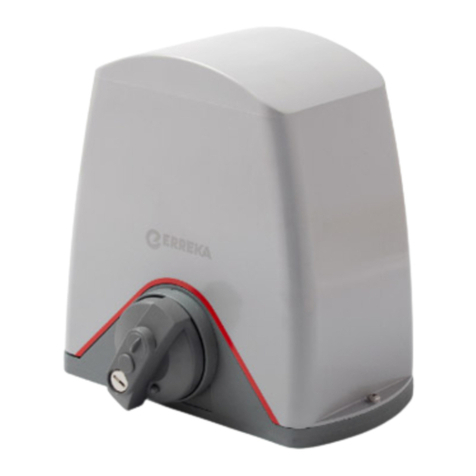
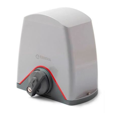
  9. Erreka CICLON Operating instructions

Erreka CICLON Operating instructions

5
CICLON
Quick installation and programming guide English
WARNING
This quick guide is a summary of the complete installation manual. The manual contains safety warnings and
other explanations which must be taken into account. The installation manual can be downloaded by going
to the "Downloads" section of Erreka website:
http://www.erreka.com/Automatismos/descargaDocumentos.aspx
*4 x 1mm2
(max. 20m)
TA
TA
E246A
TC
4 x 0,5mm2
(max. 30m)
G
2 x 0,75mm2
(max. 20m)
3 x 1,5mm2
(max. 30m)
2 x 0,5mm2
(max. 20m)
2 x 0,5mm2
(max. 20m)
RG-58/U
2 x 0,5mm2
(max. 30m)
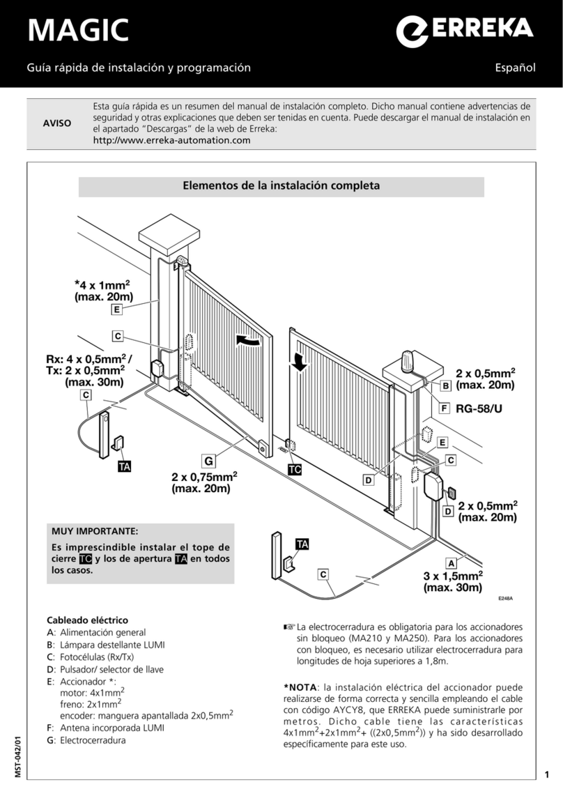
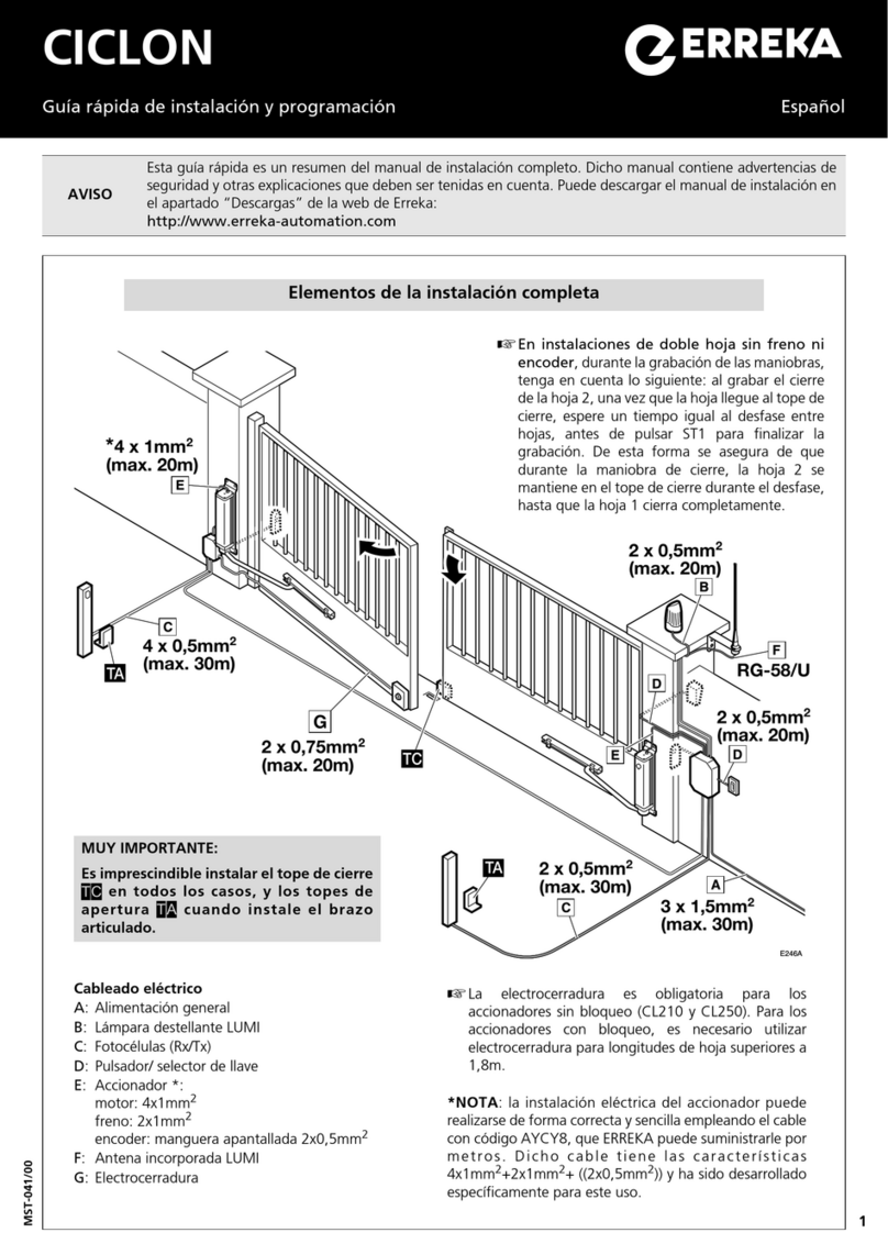
Elements of the complete installation
Electrical wiring
A: Main power supply
B: LUMI flashing light
C: Photocells (Rx/Tx)
D: Pushbutton/key switch
E: Operator *:
motor: 4x1mm2
brake: 2x1mm2
encoder: shielded cable 2x0.5mm2
F: LUMI built-in antenna
G: Electrolock
VERY IMPORTANT:
The TC closing limit switch must be
installed in all cases, and TA opening limit
switches whenever the articulated arm is
installed.
The electrolock is obligatory for operators without
lock (CL210 and CL250). For operators with lock, the
electrolock must be used for gate leaf lengths of over
1.8m.
*NOTE: the electrical installation of the operator can be
done correctly and straightforwardly using the cable with
AYCY8 code, which ERREKA can supply by metre. This
cable has the characteristics 4x1mm2+2x1mm2+
((2x0.5mm2)) and was developed specifically for this use.
In dual leaf facilities without brake or
encoder, the following should be taken into
account when programming the operations:
when programming the closing of leaf 2 and the
leaf reaches the closing limit switch, wait for a
time equal to the lapse between leaves before
pressing ST1 to end programming. This ensures
that, during the closing operation, leaf 2 remains
at the closing limit switch during lapse until leaf
1 closes completely.
MST-041/00
6
D246A D246B
Unlocked (only for models with brake)
Unlocked for manual operation:
•Remove the cap and insert the key (1).
•Turn the key 90° anti-clockwise (A). The gate is
free to move manually.
Lock for motorised operation:
•Turn the key (1) 90° clockwise (B).
•Remove the key and position the cap to stop
water from coming in.
500mm
100mm
M246C
100mm
548mm
N32901
580mm
360mm
M246B
548mm
435 mm
N32001
410mm
340mm
M246A
100mm
(80mm)
548mm
(600mm)
500mm
(1000mm)
ACL16/ N32501
610mm
(990mm)
120 mm
Assembly levels
Assembly with sliding arm ACL16/
N32501 (inward opening)
The TC closing limit switch must be
installed with this type of arm.
The levels with no brackets
correspond to models
CLS210F/
CL210F (T2000VFI)/ CL210 with arm
N32501.
The levels between brackets
correspond to models CLS250F/
CL250F/ CL250 with arm ACL16.
Assembly with sliding arm
N32901 (outward opening)
The TC closing limit switch must be
installed with this type of arm.
The exterior opening arm is only
valid for the operators CLS210F/
CL210F (T2000VFI)/ CL210.
Assembly with articulated arm
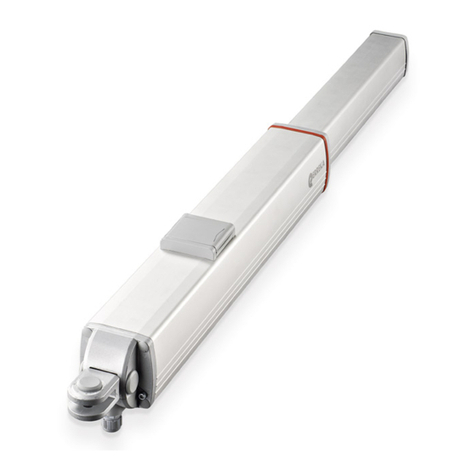
N32001 (inward opening)
TC closing limit switch and TA
opening limit switch must be installed
with this type of arm.
The N32001 articulated arm is
only valid for the models CLS210F/
CL210F (T2000VFI)/ CL210.
7
P246E
P246D
3
P246F
P246H
Assembly
B1 Mount the drag wheel (1) on the operator shaft.
B2 Install the arm (2) and the cap (3) on the drag
wheel.
B3
Close the gate, pull the arm (1) a maximum of
670 mm and mark the positions A and B
. Secure
the bracket (2) in this position.
1 Mount the operator (1) on the bracket (2) using the
screws and washers supplied (3).
Then mount the unit on the wall
.
Remember that the bracket corresponding to models
CLS210F/ CL210F (T2000VFI) / CL210 is shown.
The bracket for models CLS250F/ CL250F/ CL250 has
some differences, although assembly is carried out in a
similar way.
P246A
A1 Mount the drag wheel (1) on the
operator shaft.
A2 Install the arm (2) and the cap (3)
on the drag wheel.
A3 Close the gate and mark position A
on it.
Open the gate and mark position B
on it.
Secure the track so points A and B
are aligned inside.
A4 Position the closing and opening
limit switches (1) on the track using
the plate (2) (the opening limit
switch is shown in the figure).
P246G
3
OPTION A: assembly with sliding arm
OPTION B: assembly with articulated arm
8
P246Z
ENCODER1 ENCODER2
P13 P14 P15 P16 P17 P18 P19 P20 P21 P22 P23
GND
V+
NG1
NG2
GND
V+
NG1
NG2
+
-FT
(Test)
AUX
24 Vdc
T1
FT1
P1 P2 P3
T2
FT2
P4 P5 P6
TOP
P7 P8
WARNING
LIGHT
P9
P10
24V
P11
P12
LOCK
Lamp.
G9 G10
G7 G8
Courtesy
Light
G1 G2 G3
MOTOR1
G4 G5 G6
MOTOR2
CN13
NL
POWER - 230V
P24 P25
EDGE
A2
T1
FT1
P1 P2 P3
T2
FT2
P4 P5 P6
TOP
P7 P8
WARNING
LIGHT
P9
P10
24V
P11
P12
LOCK
ST1
V+
GND
SGN1
NL
POWER - 230V
VIVO-M203:
230V, 50Hz
VIVO-M203M:
125V, 60Hz
F4
F1
F2
F3
ST2
A1
EPS1
Electrical connections, control board VIVO-M203
M1 and M2 motor connection:
G4/G1: brown cable
G5/G2: black cable
G6/G3: grey cable
C: capacitor; CL210 / CL210F (T2000VFI) / CLS210F: 5μF; CL250/ CL250F/ CLS250F: 8μF
Encoder connection (if available):
V+: red cable
GND: mesh
SGN1: blue cable
Check the control board instructions to connect the other
components and carry out programming.
EPS1
L1
COM
L2
F1
FR2
FR1
P246Y
M203: 230V/50Hz
Brake cabling by way of EPS1 (VIVO-M203, parameter Ab01)
DL1: Red LED, FR1 activation
DL2: Green LED, FR2 activation
COM: orange cable (models with encoder)
white cable (models without encoder)
L1, L2: purple cable (models with encoder)
red cable (models without encoder)

Other manuals for CICLON

1

Other Erreka Gate Opener manuals

Erreka VIVO-D102 Operating instructions

Erreka

Erreka VIVO-D102 Operating instructions

Erreka VULCAN D User manual

Erreka

Erreka VULCAN D User manual

Erreka CA53 Operating instructions

Erreka

Erreka CA53 Operating instructions

Erreka ARC Series User guide

Erreka

Erreka ARC Series User guide

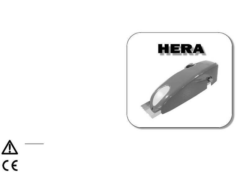
Erreka HERA Technical document

Erreka

Erreka HERA Technical document

Erreka IZAR User guide

Erreka

Erreka IZAR User guide

Erreka LINCE Operating instructions

Erreka

Erreka LINCE Operating instructions

Erreka AXIL Operating instructions

Erreka

Erreka AXIL Operating instructions

Erreka BUL BL33 Operating instructions

Erreka

Erreka BUL BL33 Operating instructions

Erreka TEMIS User manual

Erreka

Erreka TEMIS User manual

Erreka KAIROS MSB-027/01 User manual

Erreka

Erreka KAIROS MSB-027/01 User manual

Erreka MAGIC Operating instructions

Erreka

Erreka MAGIC Operating instructions

Erreka DINGO Operating instructions

Erreka

Erreka DINGO Operating instructions

Erreka MAGIC Operating instructions

Erreka

Erreka MAGIC Operating instructions

Erreka AXIL Series User manual

Erreka

Erreka AXIL Series User manual

Erreka ARES User guide

Erreka

Erreka ARES User guide

Erreka VULCAN S User manual

Erreka

Erreka VULCAN S User manual

Erreka ARC Series User guide

Erreka

Erreka ARC Series User guide

Erreka Fenix User guide

Erreka

Erreka Fenix User guide

Erreka VULCAN D Operating instructions

Erreka

Erreka VULCAN D Operating instructions

Erreka SIRIUS Operating instructions

Erreka

Erreka SIRIUS Operating instructions

Erreka DINGO User manual

Erreka

Erreka DINGO User manual

Erreka Puma Operating instructions

Erreka

Erreka Puma Operating instructions

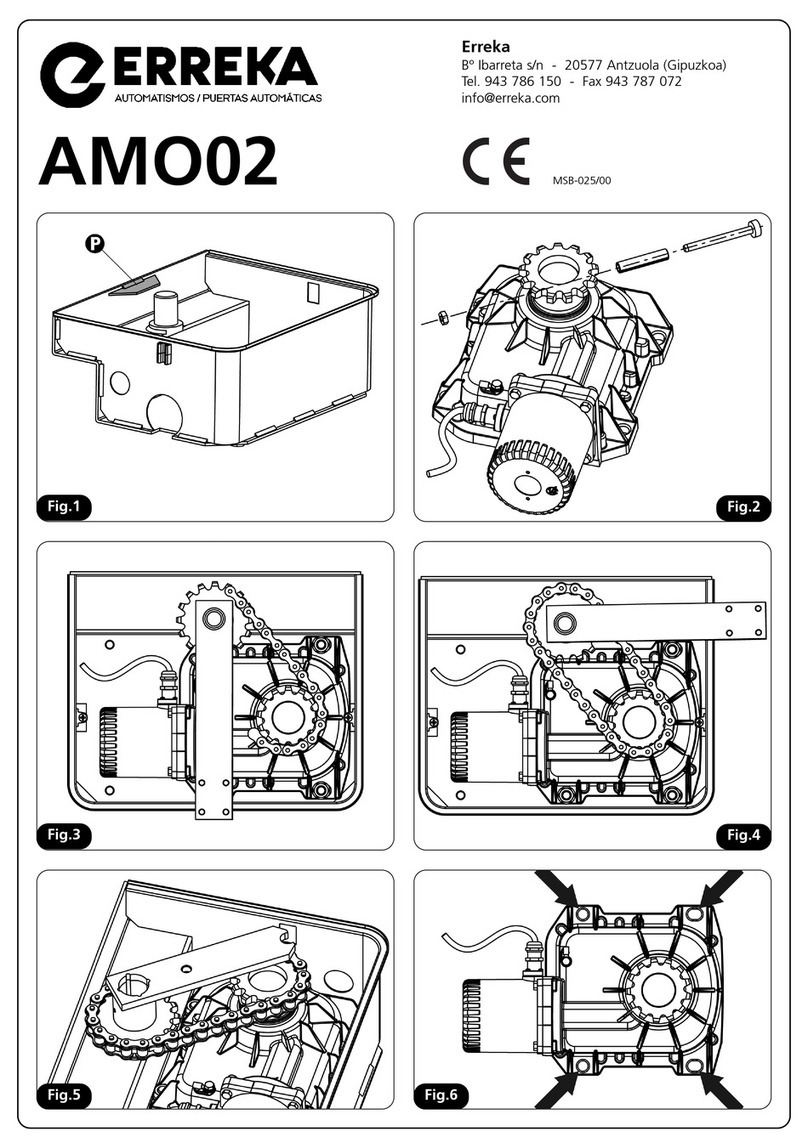
Erreka AMO02 User manual

Erreka

Erreka AMO02 User manual

Popular Gate Opener manuals by other brands

CAME 806SL-0370 manual

CAME

CAME 806SL-0370 manual

Merlin G715D Instructions for installation and use

Merlin

Merlin G715D Instructions for installation and use

Topens AT6132 user manual

Topens

Topens AT6132 user manual

SOMFY Axorn 50 manual

SOMFY

SOMFY Axorn 50 manual

RIB K800 24V manual

RIB

RIB K800 24V manual

Motostar ECLISTAR installation manual

Motostar

Motostar ECLISTAR installation manual

Platinum BLSL2250 Installation instructions & owner's manual

Platinum

Platinum BLSL2250 Installation instructions & owner's manual

DoorHan SLIDING-3000 manual

DoorHan

DoorHan SLIDING-3000 manual

King gates Star 224 manual

King gates

King gates Star 224 manual

FAAC Safe Zone S418 manual

FAAC

FAAC Safe Zone S418 manual

Daspi STER instruction manual

Daspi

Daspi STER instruction manual

Genius FALCON 5 manual

Genius

Genius FALCON 5 manual

Elsema AXIOM iS600 Series user manual

Elsema

Elsema AXIOM iS600 Series user manual

Roger Technology M30 Series INSTRUCTIONS AND RECOMMENDATIONS FOR THE INSTALLER

Roger Technology

Roger Technology M30 Series INSTRUCTIONS AND RECOMMENDATIONS FOR THE INSTALLER

Nice Pop Series Instructions and warnings for the fitter

Nice

Nice Pop Series Instructions and warnings for the fitter

KEY RAY user manual

KEY

KEY RAY user manual

HI MOTIONS BIFOLDSTD manual

HI MOTIONS

HI MOTIONS BIFOLDSTD manual

Beninca DU.IT14 User handbook

Beninca

Beninca DU.IT14 User handbook

manuals.online logo
manuals.online logoBrands
  • About & Mission
  • Contact us
  • Privacy Policy
  • Terms and Conditions

Copyright 2025 Manuals.Online. All Rights Reserved.