4 5
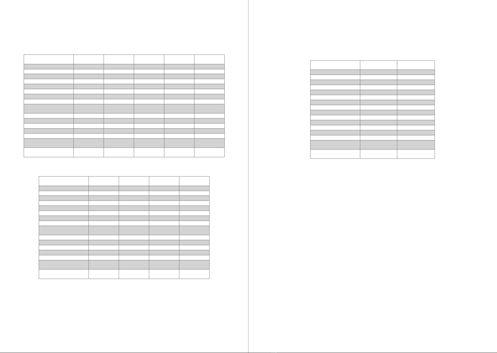
TECHNICAL CHARACTERISTICS
DZ RIO 400 DZ RIO R 500 DZ RIO R 700 DZ RIO 300
CUSTOM MONO
DZ RIO 350
MONO SP
TYPE OF OPERATOR SLIDING SLIDING SLIDING SLIDING SLIDING
MODEL SINGLE-PHASE SINGLE-PHASE SINGLE-PHASE SINGLE-PHASE SINGLE-PHASE
RATED VOLTAGE 127V / 220V 127V / 220V 127V / 220V 127V / 220V 127V / 220V
NOMINAL FREQUENCY 60 Hz 60 Hz 60 Hz 60 Hz 60 Hz
RATED POWER 370 W / 515 W 300 W / 286 W 400 W / 450 W 250 W / 260 W 300 W / 480 W
ENGINE ROTATION 1740 1740 1740 1740 1740
NOMINAL CHAIN 3,1 A / 2,25 A 3,05 A / 2,35 A 3,1 A / 2,1 A 2 A / 1,5 A 2 A / 2 A
REDUCTION 1:23 1:23 1:23 1:23 1:23
LINEAR SPEED 13,3m/min ( Z14)
17,1 m/min (Z18)
13,3m/min ( Z14)
17,1 m/min (Z18)
13,3m/min ( Z14)
17,1 m/min (Z18)
13,3m/min ( Z14)
17,1 m/min (Z18) 22m/min ( Z22)
MANEUVERS 30 40 60 20 30
DEGREE OF PROTECTION IPX4 IPX4 IPX4 IPX4 IPX4
TEMPERATURE RANGE -5° C / +50° C -5° C / +50° C -5° C / +50° C -5° C / +50° C -5° C / +50° C
TYPE OF INSULATION Class B, 130º C Class B, 130º C Class B, 130º C Class B, 130º C Class B, 130º C
LIMIT SWITCH Analog / Digital Analog / Digital Analog / Digital Analog / Digital Analog / Digital
MAX. MASS FROM THE LEAF
OF THE GATE 400 Kg 500 Kg 700 Kg 300 Kg 350 Kg
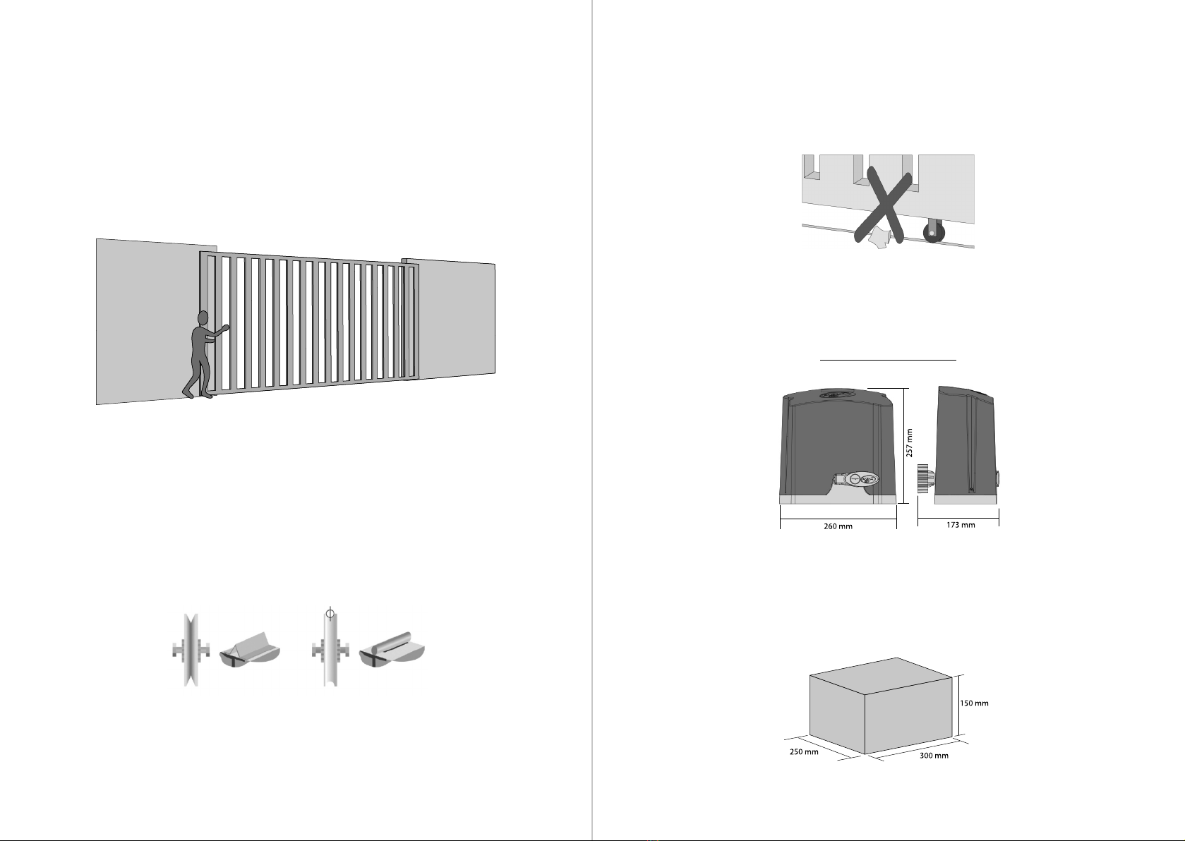
MAX. DIMENSION OF THE
GATE
HEIGHT = 2.5 m
LENGTH. = 3.0 m
HEIGHT = 2.5 m
LENGTH. = 3.0 m
HEIGHT = 2.5 m
LENGTH. = 3.0 m
HEIGHT = 2.5 m
LENGTH. = 3.0 m
HEIGHT = 2.5 m
LENGTH. = 3.0 m
DZ RIO 350
JETFLEX
DZ RIO 500
JETFLEX
DZ RIO R 600
JETFLEX
DZ RIO R 800
JETFLEX
TYPE OF OPERATOR SLIDING SLIDING SLIDING SLIDING
MODEL THREE PHASE THREE PHASE THREE PHASE THREE PHASE
RATED VOLTAGE 127V / 220V 127V / 220V 127V / 220V 127V / 220V
NOMINAL FREQUENCY 60 Hz 60 Hz 60 Hz 60 Hz
RATED POWER 340 W / 280 W 330 W / 270 W 370 W / 310 W 280 W / 230 W
ENGINE ROTATION 5800 5800 5800 5800
NOMINAL CHAIN 2,4 A / 2,5 A 3,4 A / 2,0 A 3,6 A / 2,1 A 2,8 A / 1,6 A
REDUCTION 1:23 1:23 1:23 1:23
LINEAR SPEED 33 m/min ( Z14)
42,9 m/min (Z18)
33 m/min ( Z14)
42,9 m/min (Z18)
33 m/min ( Z14)
42,9 m/min (Z18)
33 m/min ( Z14)
42,9 m/min (Z18)
MANEUVERS 30 40 50 60
DEGREE OF PROTECTION IPX4 IPX4 IPX4 IPX4
TEMPERATURE RANGE -5° C / +50° C -5° C / +50° C -5° C / +50° C -5° C / +50° C
TYPE OF INSULATION Class B, 130° C Class B, 130° C Class B, 130° C Class B, 130° C
LIMIT SWITCH HYBRID HYBRID HYBRID HYBRID
MAX. MASS FROM THE LEAF
OF THE GATE 350 Kg 500 Kg 600 Kg 800 Kg
MAX. DIMENSION OF THE
GATE
HEIGHT = 2.5 m
LENGTH. = 3.0 m
HEIGHT = 2.5 m
LENGTH. = 3.0 m
HEIGHT = 2.5 m
LENGTH. = 3.0 m
HEIGHT = 2.5 m
LENGTH. = 3.0 m
DZ RIO PREDIAL 700 DZ RIO PREDIAL 800
JETFLEX
TYPE OF OPERATOR SLIDING SLIDING
MODEL SINGLE-PHASE THREE PHASE
RATED VOLTAGE 127V / 220V 127V / 220V
NOMINAL FREQUENCY 60 Hz 60 Hz
RATED POWER 400 W / 450 W 280 W / 230 W
ENGINE ROTATION 1740 5800
NOMINAL CHAIN 3,1 A / 2,1 A 2,8 A / 1,6 A
REDUCTION 1:23 1:23
LINEAR SPEED 17,1 m/min (Z12) 42,9 m/min (Z12)
MANEUVERS 60 70
DEGREE OF PROTECTION IPX4 IPX4
TEMPERATURE RANGE -5° C / +50° C -5° C / +50° C
TYPE OF INSULATION Class B, 130° C Class B, 130° C
LIMIT SWITCH Analog HYBRID
MAX. MASS FROM THE LEAF
OF THE GATE 700 Kg 800 Kg
MAX. DIMENSION OF THE
GATE
HEIGHT = 2.5 m
LENGTH. = 3.0 m
HEIGHT = 2.5 m
LENGTH. = 3.0 m