2
CONTENTS
TECHNICAL DATA
. . . . . . . . . . . . . . . . . . . . . . . . . . . . . . page
3
burner models . . . . . . . . . . . . . . . . . . . . . . . . . . . . . . . . . . . . . . . 3
Accessories . . . . . . . . . . . . . . . . . . . . . . . . . . . . . . . . . . . . . . . . . 3
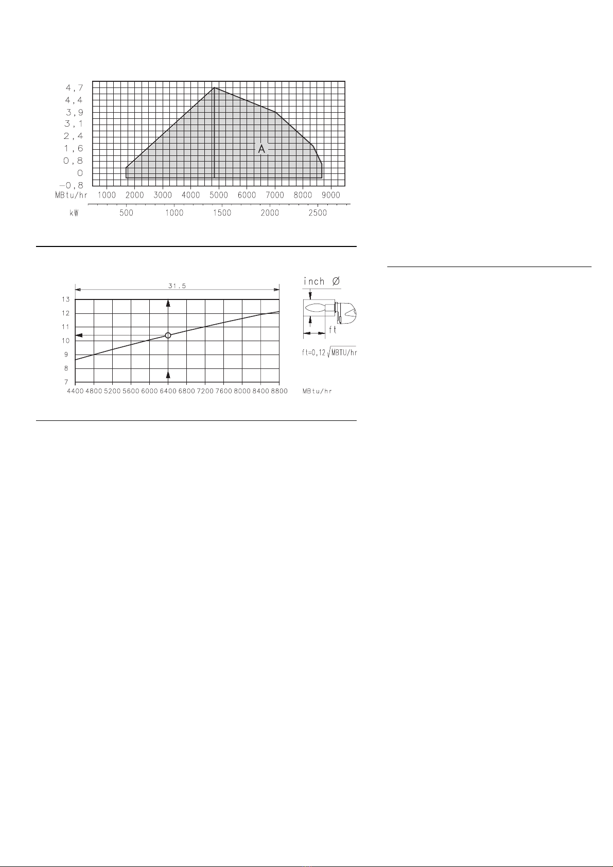
Burner description . . . . . . . . . . . . . . . . . . . . . . . . . . . . . . . . . . . . 4
Packaging - Weight. . . . . . . . . . . . . . . . . . . . . . . . . . . . . . . . . . . . 4
Max. dimensions. . . . . . . . . . . . . . . . . . . . . . . . . . . . . . . . . . . . . . 4
Standard equipment. . . . . . . . . . . . . . . . . . . . . . . . . . . . . . . . . . . 4
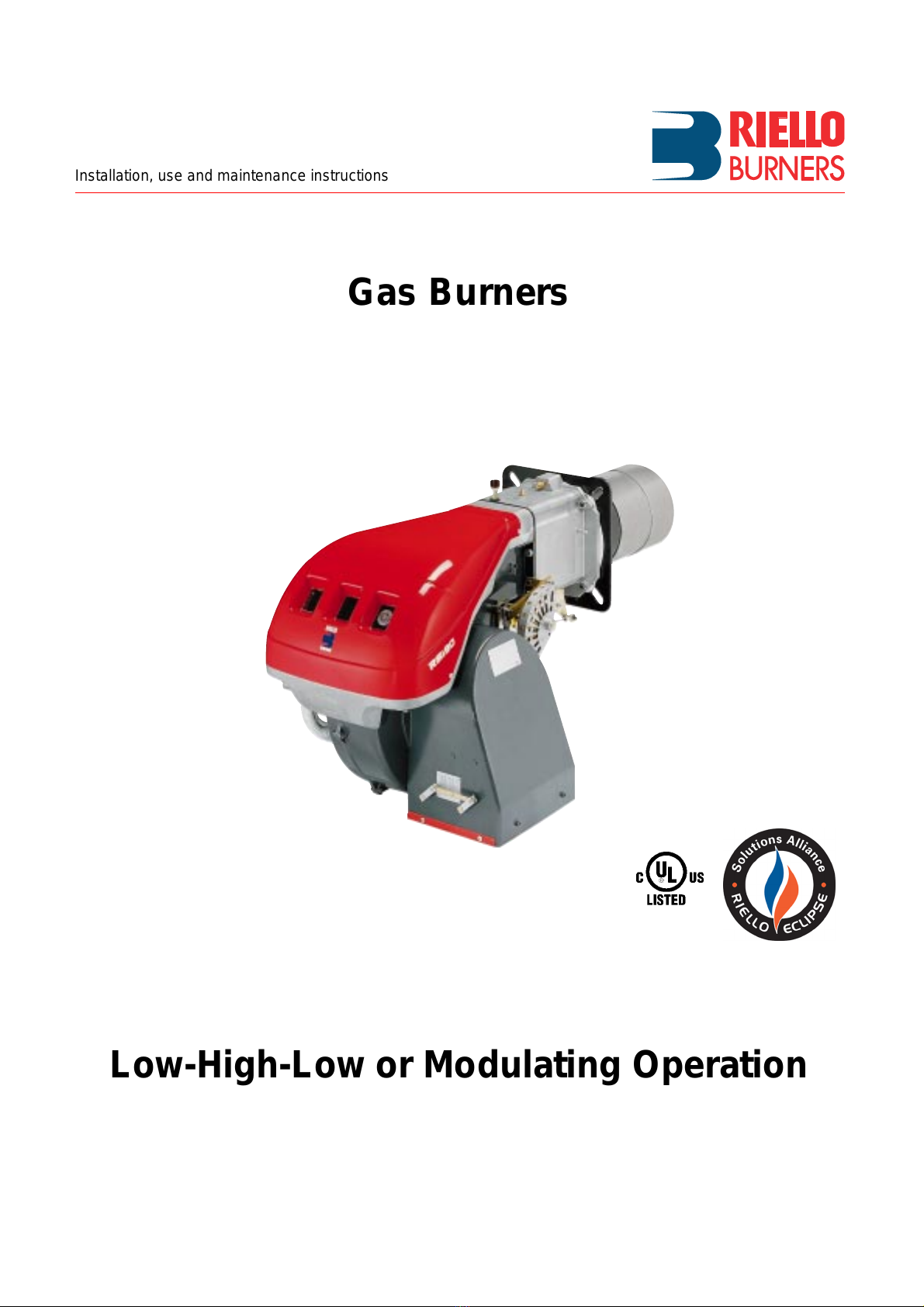
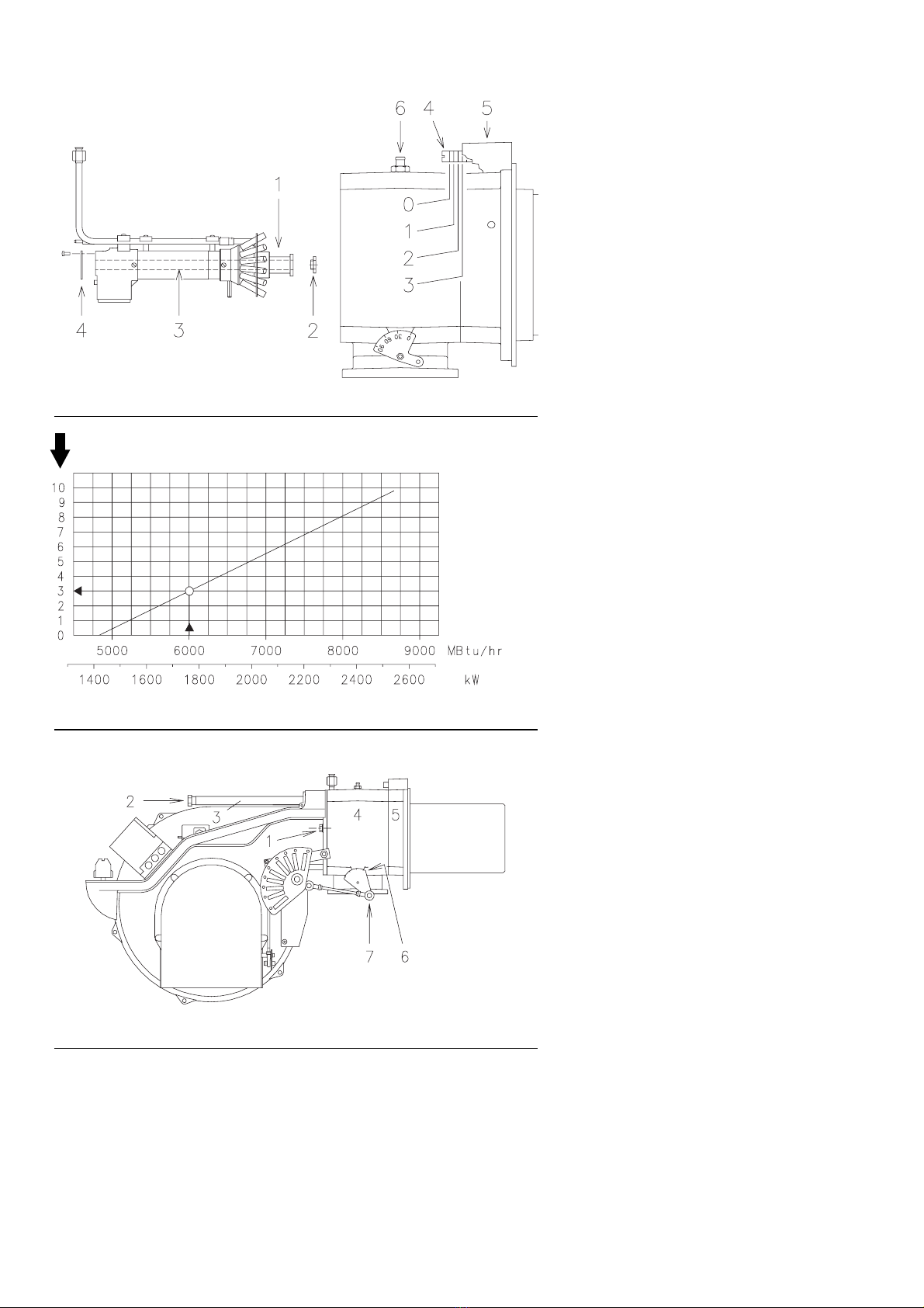
Firing rates . . . . . . . . . . . . . . . . . . . . . . . . . . . . . . . . . . . . . . . . . . 5
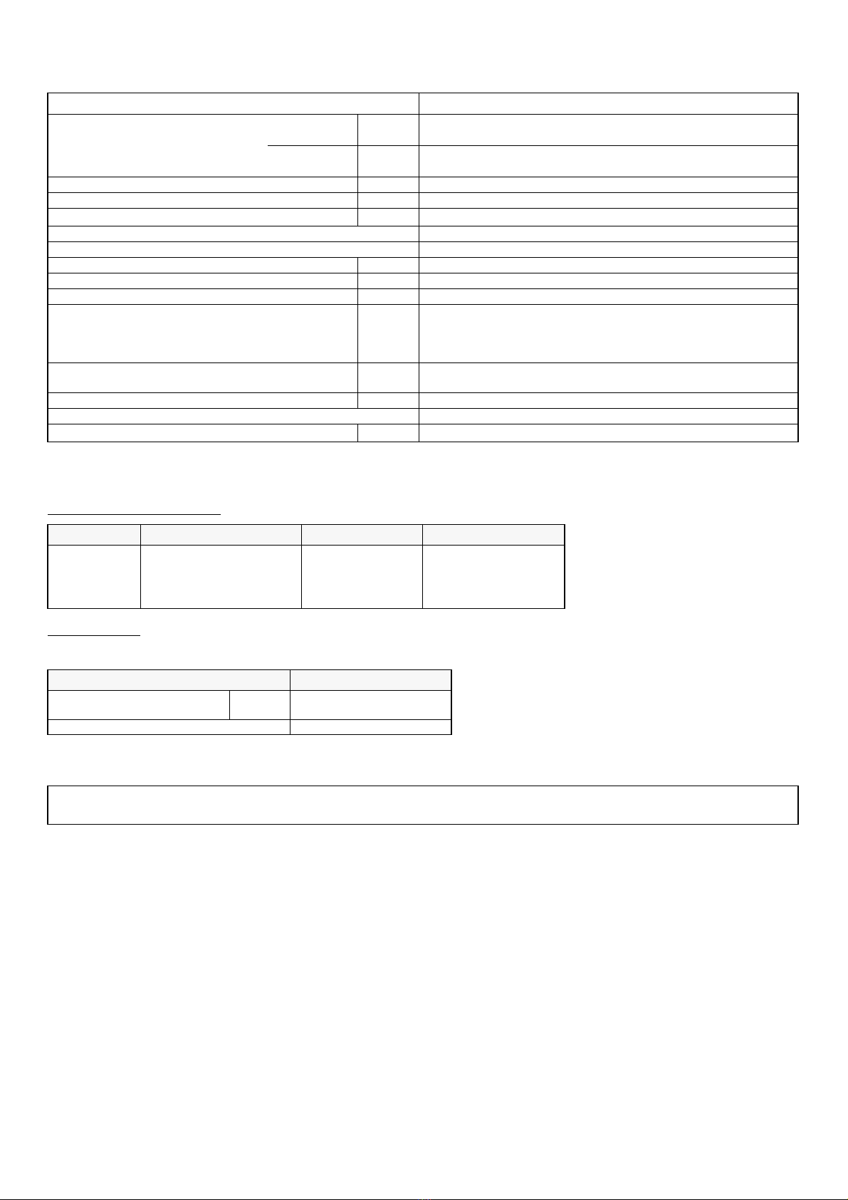
Minimum furnace dimensions. . . . . . . . . . . . . . . . . . . . . . . . . . . . 5
Gas pressure . . . . . . . . . . . . . . . . . . . . . . . . . . . . . . . . . . . . . . . . 6
INSTALLATION . . . . . . . . . . . . . . . . . . . . . . . . . . . . . . . . . . . . . . 7
Boiler plate . . . . . . . . . . . . . . . . . . . . . . . . . . . . . . . . . . . . . . . . . . 7
Blast tube length . . . . . . . . . . . . . . . . . . . . . . . . . . . . . . . . . . . . . 7
Securing the burner to the boiler . . . . . . . . . . . . . . . . . . . . . . . . . 7
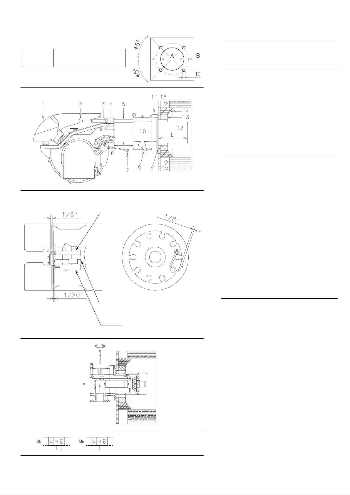
Ignition pilot adjustment . . . . . . . . . . . . . . . . . . . . . . . . . . . . . . . . 7
Combustion head adjustment. . . . . . . . . . . . . . . . . . . . . . . . . . . . 8
Gas piping . . . . . . . . . . . . . . . . . . . . . . . . . . . . . . . . . . . . . . . . . . 9
Adjustments before first firing. . . . . . . . . . . . . . . . . . . . . . . . . . . 10
Servomotor. . . . . . . . . . . . . . . . . . . . . . . . . . . . . . . . . . . . . . . . . 11
Burner starting . . . . . . . . . . . . . . . . . . . . . . . . . . . . . . . . . . . . . . 12
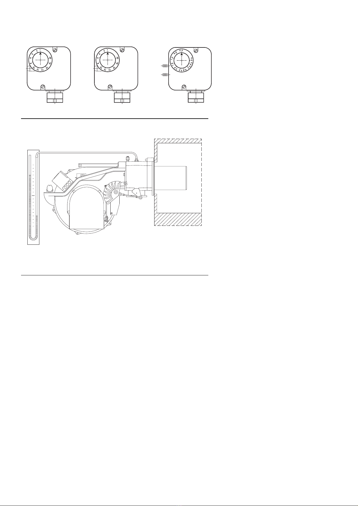
Air pressure switch. . . . . . . . . . . . . . . . . . . . . . . . . . . . . . . . . . . 13
Maximum gas pressure switch. . . . . . . . . . . . . . . . . . . . . . . . . . 13
Minimum gas pressure switch . . . . . . . . . . . . . . . . . . . . . . . . . . 13
Flame present check . . . . . . . . . . . . . . . . . . . . . . . . . . . . . . . . . 13
Maintenance. . . . . . . . . . . . . . . . . . . . . . . . . . . . . . . . . . . . . . . . 14
Factory wiring diagram - burner mounted LFL . . . . . . . . . . . . . . 15
Field wiring diagram - Burner mounted LFL. . . . . . . . . . . . . . . . 16
Factory wiring diagram - remote panel. . . . . . . . . . . . . . . . . . . . 17
Appendix - Burner firing rates according to air density. . . . . . . . 18
Siemens LFL control sequence of operation . . . . . . . . . . . . . . . 19
Siemens LFL troubleshooting guide. . . . . . . . . . . . . . . . . . . . . . 20
Burner start up report. . . . . . . . . . . . . . . . . . . . . . . . . . . . . . . . . 21
N.B.
Figures mentioned in the text are identified as follows:
1)(A) =part 1 of figure A, same page as text;
1)(A)p.4 =part 1 of figure A, page number 4.
WARNING
If you smell gas:
• Do not touch any electrical items.
• Open all windows.
• Close all gas supply valves.
• Contact your local gas authority immediately.
Do not store flammable or hazardous materials in the vicinity
of fuel burning appliances.
Improper installation, adjustment, alteration, service or main-
tenance can cause property damage, personal injury or
death. Refer to this manual for instructional or additional in-
formation. Consulta certified installer,servicerepresentative
or the gas supplier for further assistance.
Burner shall be installed in accordance with manufacturers
requirements as outlined in this manual, local codes and au-
thorities having juristiction.