manuals.online logo
Brands
  1. Home
  2. •
  3. Brands
  4. •
  5. Riello
  6. •
  7. Gateway
  8. •
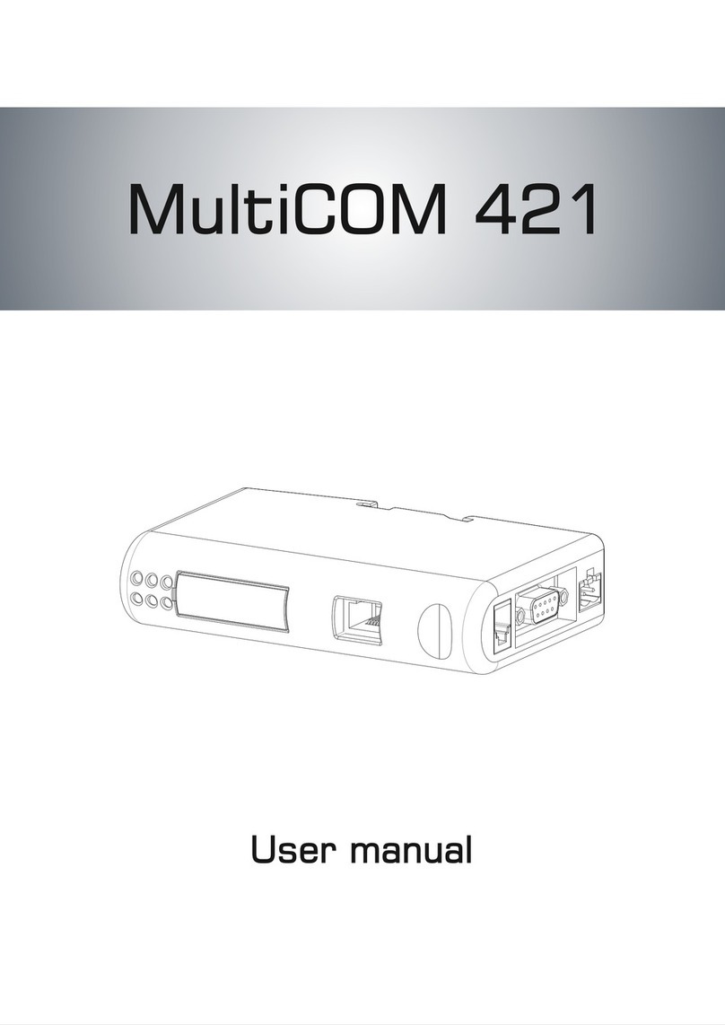
  9. Riello MultiCOM 421 User manual

Riello MultiCOM 421 User manual

Other manuals for MultiCOM 421

1

Other Riello Gateway manuals

Riello N35 User manual

Riello

Riello N35 User manual

Riello MultiCOM 421 User manual

Riello

Riello MultiCOM 421 User manual

Riello N35 Quick start guide

Riello

Riello N35 Quick start guide

Popular Gateway manuals by other brands

Telecom FM onestream gfx Programming guide

Telecom FM

Telecom FM onestream gfx Programming guide

UfiSpace LoRa GPE810U Quick setup guide

UfiSpace

UfiSpace LoRa GPE810U Quick setup guide

Merak MMk-736F Quick setup guide

Merak

Merak MMk-736F Quick setup guide

Robustel R3010 user guide

Robustel

Robustel R3010 user guide

turck BL20-PG-EN-V3 user manual

turck

turck BL20-PG-EN-V3 user manual

IBM Security Web Gateway Appliance quick start guide

IBM

IBM Security Web Gateway Appliance quick start guide

SSS Siedle Smart Gateway Commissioning instructions

SSS Siedle

SSS Siedle Smart Gateway Commissioning instructions

ADTRAN 424RG Installation

ADTRAN

ADTRAN 424RG Installation

Chorus Hyperfibre XGS-250WX-A user guide

Chorus

Chorus Hyperfibre XGS-250WX-A user guide

Dragino G308 user manual

Dragino

Dragino G308 user manual

Data Domain DD690g Installation and setup guide

Data Domain

Data Domain DD690g Installation and setup guide

Raritan Laptop Release notes

Raritan

Raritan Laptop Release notes

Haivision Torpedo quick start guide

Haivision

Haivision Torpedo quick start guide

ATCOM AG-268 user manual

ATCOM

ATCOM AG-268 user manual

LST M500RFE-AS Specification sheet

LST

LST M500RFE-AS Specification sheet

Vega VEGA BS-3 user manual

Vega

Vega VEGA BS-3 user manual

Kinnex Media Gateway quick start guide

Kinnex

Kinnex Media Gateway quick start guide

2N Telekomunikace 2N StarGate user manual

2N Telekomunikace

2N Telekomunikace 2N StarGate user manual

manuals.online logo
manuals.online logoBrands
  • About & Mission
  • Contact us
  • Privacy Policy
  • Terms and Conditions

Copyright 2025 Manuals.Online. All Rights Reserved.

- 0MNACCMCAENQA-
4
INSTALLATION
1. Remove the cover of the UPS expansion slot by removing the two retaining screws.
2. Insert MultiCOM 302 in the slot.
3. Fix the cover provided using the screws previously removed.
4. Connect the PROFINET Gateway to the MultiCOM 302 using the cable provided with the device.
NOTE: if necessary, you can also use another cable realized in accordance with the specifications (see Connection cable
MultiCOM 302 ↔ PROFINET Gateway).
5. Connect the PROFINET Gateway to the PROFINET Network.
6. Connect the power cable and apply power.
CONNECTION CABLE MULTICOM302↔PROFINETGATEWAY
DB9 male
PIN
connect
to
RJ-45
PIN
5
↔
2
9↔3
8
↔
4
NOTE: Use a twisted pair to connect PIN #9 and #8 of DB9 to PIN #3 and #4 of RJ-45
DIN-RAIL MOUNTING
To snap the gateway
on
, first press it downwards (1) to
compress the spring in the DIN-rail mechanism, then push
it against the DIN-rail as to make it snap on (2). To snap the gateway off, push it downwards (1) and pull it out
from the DIN-rail (2), as to make it snap off from the DIN-rail.
- 0MNACCMCAENQA-
1
QUICK START MULTICOM 421
For additional information, please download User Manual from manufacturer’s website.
PRESENTATION
IN THE BOX
MultiCOM 302 board
PROFINETGateway
Connection cable between MultiCOM 302
and
PROFI
NET
Gateway
EXTERNAL VIEW
PROFINET Connector
Status LEDs
Reserved
MultiCOM 302 Connector
Power Connector
DIN-rail Connector
- 0MNACCMCAENQA-
2
PROFINET GATEWAY CONNECTORS AND LEDS
PROFINETCONNECTOR
PIN Signal
1 8
Housing Cable Shield
1 TD+
2 TD-
3 RD+1
4 Termination
5 Termination
6 RD-
7 Termination
8 Termination
POWER CONNECTOR
PIN
Description
1 2
1+24 VDC (300 mA required)
2GND
Note: no power supply is provided with the device.
MULTICOM302CONNECTOR
PIN
Description
5
1
9 6
(female)
1, 2, 3, 4, 6, 7 -
5Signal Ground
8RS485+
9RS485-
- 0MNACCMCAENQA-
3
STATUSLEDS
# Indication Meaning
1 - Communication
Status
Off Not online
Green Online, connection with IO established,
IO controller in run state
Flashing Green Online, connection with IO established,
IO controller in stop state
2 - Module
Status
Off No power / Not initialized
Green Initialized, no errors
1 Sequential Green Blink Diagnostic data available
2 Sequential Green Blinks Used by engineering tool to identify the
module
1 Sequential Red Blink Configuration error
3 Sequential Red Blinks No station name or no IP address
assigned
4 Sequential Red Blinks Internalerror
3 - Link, activity Off No link
Green Connected to an Ethernet network
Flashing Green Packets are received or transmitted
4 - Not used - -
5 - Subnet
Status
Flashing Green Running, but one or more transaction
errors
Green Running
Red Transaction error/timeout or subnet
stopped
6 - Device
Status
Off Power off
Alternating Red/Green Invalid or missing configuration
Green Initializing
Flashing Green Running
Red Bootloader mode
Flashing Red Contact support department
MULTICOM 302 JUMPER AND DIP SWITCHES SETTINGS