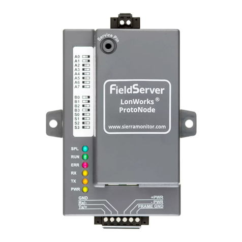
Riello MultiCOM 421 User manual


INTRODUCTION
Thank you for choosing our product.
The accessories described in this manual are of the highest quality, carefully designed and built in order to ensure excellent
performance.
This manual contains detailed instructions on how to install and use the product.
This manual must be stored in a safe place and CONSULTED BEFORE USING THE DEVICE for proper usage instructions as
well as maximum performance from the device itself.
NOTE: Some images contained in this document are for informational purposes only and may not faithfully demonstrate the parts of
the product they represent.
SAFETY
This part of the manual contains SAFETY precautions that must be followed scrupulously.
Ensure that the connectors subjected to high voltages are correctly isolated.
▪The device has been designed for professional use and is therefore not suitable for use in the home.
▪The device has been designed to operate only in closed environments. It should be installed in rooms where there are no
inflammable liquids, gas or other harmful substances.
▪Take care that no water or liquids and/or foreign bodies fall into the device.
▪In the event of a fault and/or impaired operation of the device, do not attempt to repair it but contact the authorized service
centre.
▪The device must be used exclusively for the purpose for which it was designed. Any other use is to be considered improper
and as such dangerous. The manufacturer declines all responsibility for damage caused by improper, wrong and
unreasonable use.
ENVIRONMENTAL PROTECTION
Our company devotes abundant resources to analysing environmental aspects in the development of its products. All our products
pursue the objectives defined in the environmental management system developed by the company in compliance with applicable
standards.
Hazardous materials such as CFCs, HCFCs or asbestos have not been used in this product.
When evaluating packaging, the choice of material has been made favouring recyclable materials.
Please separate the different material of which the packaging is made and dispose of all material in compliance with applicable
standards in the country in which the product is used.
DISPOSING OF THE PRODUCT
The device contains internal material which (in case of dismantling/disposal) are considered TOXIC, such as electronic circuit boards.
Treat these materials according to the laws in force, contacting qualified centres. Proper disposal contributes to respect for the
environment and human health.
©The reproduction of any part of this manual, even in part, is prohibited unless authorised by the manufacturer.
The manufacturer reserves the right to change the product described at any time without prior notice for improvement purposes.

INDEX
PRESENTATION 5
IN THE BOX 5
EXTERNAL VIEW 5
PROFINET GATEWAY CONNECTORS AND LEDS 6
PROFINET CONNECTOR 6
POWER CONNECTOR 6
MULTICOM 302 CONNECTOR 6
STATUS LEDS7
MULTICOM 302 JUMPER AND DIP SWITCHES SETTINGS 7
INSTALLATION 8
CONNECTION CABLE MULTICOM 302 ↔PROFINET DP GATEWAY 8
DIN-RAIL MOUNTING 8
PROFINET I/O DATA 9

PRESENTATION
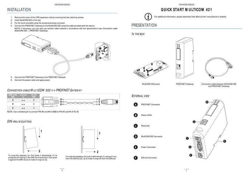
MultiCOM 421 allows to integrate the management and monitoring of the UPS into a PROFINET network.
IN THE BOX
MultiCOM 302 board
PROFINET Gateway
Connection cable between MultiCOM 302
and PROFINET Gateway
EXTERNAL VIEW
PROFINET Connector
Status LEDs
Reserved
MultiCOM 302 Connector
Power Connector
DIN-rail Connector

PROFINET GATEWAY CONNECTORS AND LEDS
PROFINET CONNECTOR
PIN
Signal
1 8
Housing
Cable Shield
1
TD+
2
TD-
3
RD+1
4
Termination
5
Termination
6
RD-
7
Termination
8
Termination
POWER CONNECTOR
PIN
Description
1 2
1
+24 VDC (300 mA required)
2
GND
Note: no power supply is provided with the device.
MULTICOM 302 CONNECTOR
PIN
Description
5 1
9 6
(female)
1, 2, 3, 4, 6, 7
-
5
Signal Ground
8
RS485+
9
RS485-

STATUS LEDS
#
Indication
Meaning
1 - Communication
Status
Off
Not online
Green
Online, connection with IO established,
IO controller in run state
Flashing Green
Online, connection with IO established,
IO controller in stop state
2 - Module
Status
Off
No power / Not initialized
Green
Initialized, no errors
1 Sequential Green Blink
Diagnostic data available
2 Sequential Green Blinks
Used by engineering tool to identify the
module
1 Sequential Red Blink
Configuration error
3 Sequential Red Blinks
No station name or no IP address
assigned
4 Sequential Red Blinks
Internal error
3 - Link, activity
Off
No link
Green
Connected to an Ethernet network
Flashing Green
Packets are received or transmitted
4 - Not used
-
-
5 - Subnet
Status
Flashing Green
Running, but one or more transaction
errors
Green
Running
Red
Transaction error/timeout or subnet
stopped
6 - Device
Status
Off
Power off
Alternating Red/Green
Invalid or missing configuration
Green
Initializing
Flashing Green
Running
Red
Bootloader mode
Flashing Red
Contact support department
MULTICOM 302 JUMPER AND DIP SWITCHES SETTINGS

INSTALLATION
1. Remove the cover of the UPS expansion slot by removing the two retaining screws.
2. Insert MultiCOM 302 in the slot.
3. Fix the cover provided using the screws previously removed.
4. Connect the PROFINET Gateway to the MultiCOM 302 using the cable provided with the device.
NOTE: if necessary, you can also use another cable realized in accordance with the specifications (see Connection cable
MultiCOM 302 ↔ PROFINET Gateway).
5. Connect the PROFINET Gateway to the PROFINET Network.
6. Connect the power cable and apply power.
CONNECTION CABLE MULTICOM 302 ↔PROFINET DP GATEWAY
DB9 male
PIN
connect
to
RJ-45
PIN
5
↔
2
9
↔
3
8
↔
4
NOTE: Use a twisted pair to connect PIN #9 and #8 of DB9 to PIN #3 and #4 of RJ-45
DIN-RAIL MOUNTING
To snap the gateway on, first press it downwards (1) to
compress the spring in the DIN-rail mechanism, then push
it against the DIN-rail as to make it snap on (2).
To snap the gateway off, push it downwards (1) and pull it out
from the DIN-rail (2), as to make it snap off from the DIN-rail.

PROFINET I/O DATA
The UPS’s values are presented to the Master PLC/Controller as easily processed I/O data.
INPUT DATA
REGISTER #
BYTE #
DESCRIPTION
UNIT
High
Low
0
0
1
States / alarms 1
1
2
3
States / alarms 2
2
4
5
Charge%
%
3
6
7
Autonomy
Minutes
4
8
9
RESERVED
5
10
11
Load phase L1
%
6
12
13
Load phase L2
%
7
14
15
Load phase L3
%
8
16
17
Input voltage (Ph-N) V1
V
9
18
19
Input voltage (Ph-N) V2
V
10
20
21
Input voltage (Ph-N) V3
V
11
22
23
Input frequency
Hz/10
12
24
25
Output voltage (Ph-N) V1
V
13
26
27
Output voltage (Ph-N) V2
V
14
28
29
Output voltage (Ph-N) V3
V
15
30
31
Output frequency
Hz/10
16
32
33
Output current phase L1
A/10
17
34
35
Output current phase L2
A/10
18
36
37
Output current phase L3
A/10
19
38
39
Output peak current phase L1
A/10
20
40
41
Output peak current phase L1
A/10
21
42
43
Output peak current phase L1
A/10
22
44
45
Battery current of positive bench
A/10
23
46
47
Battery current of negative bench
A/10
24
48
49
Battery voltage of positive bench
V/10
25
50
51
Battery voltage of negative bench
V/10
26
52
53
Output active power phase L1
kW/10
27
54
55
Output active power phase L2
kW/10
28
56
57
Output active power phase L3
kW/10
29
58
59
Output apparent power phase L1
kVA/10
30
60
61
Output apparent power phase L2
kVA/10
31
62
63
Output apparent power phase L3
kVA/10
32
64
65
Bypass voltage (Ph-N) V1
V
33
66
67
Bypass voltage (Ph-N) V2
V
34
68
69
Bypass voltage (Ph-N) V3
V
35
70
71
Bypass frequency
Hz/10
36
72
73
System temperature
°C

INPUT DATA
REGISTER #
BYTE #
DESCRIPTION
UNIT
High
Low
37
74
75
RESERVED
38
76
77
Battery temperature
°C
39
78
79
Power 1 temperature
°C
40
80
81
Power 2 temperature
°C
41
82
83
Power 3 temperature
°C
42
84
85
Input current phase L1
A/10
43
86
87
Input current phase L2
A/10
44
88
89
Input current phase L3
A/10
45
90
91
RESERVED
46
92
93
RESERVED
47
94
95
RESERVED
48
96
97
Output nominal voltage
V
49
98
99
Output nominal frequency
Hz/10
50
100
101
Output nominal power
kW/10
51
102
103
Output nominal power
kVA/10
52
104
105
Battery nominal voltage
V
53
106
107
Battery nominal capacity
Ah
54
108
109
RESERVED
55
110
111
Time from last valid UPS data processed
Seconds
56
112
113
Echo of command code
Integer
57
114
115
Echo of shutdown delay time
Seconds
58
116
117
Echo of restore delay time
Minutes
59
118
119
Command result:
0x0F00 →Ready to receive command
0x0100+Command Code →Command code is wrong
0x0200+Command Code →Command is not handled
0x0300+Command Code →Parameter out of range
0x0E00+Command Code →Command sent to the UPS
Integer
60
120
121
RESERVED
61
122
123
RESERVED
62
124
125
RESERVED
63
126
127
RESERVED
64 …107
128…
…215
RESERVED
Some measures may not be available for all the UPS. In this case, the relative register remains at 0xFFFF value.
STATES / ALARMS 1
BIT #
DESCRIPTION
15 (MSB)
Output powered
[0=NO / 1=YES]
14
UPS locked
[0=NO / 1=YES]
13
Battery working
[0=NO / 1=YES]
12
Battery low
[0=NO / 1=YES]
11
On bypass
[0=NO / 1=YES]
10
9
Normal operation
[0=NO / 1=YES]
8
7
Bypass bad
[0=NO / 1=YES]
6
Battery charging
[0=NO / 1=YES]
5
Battery charged
[0=NO / 1=YES]
4
3
Shutdown active
[0=NO / 1=YES]
2
1
Test in progress
[0=NO / 1=YES]
0 (LSB)

STATES / ALARMS 2
BIT #
DESCRIPTION
15 (MSB)
UPS failure
[0=NO / 1=YES]
14
Alarm overload
[0=NO / 1=YES]
13
Alarm temperature
[0=NO / 1=YES]
12
Input mains present
[0=NO / 1=YES]
11
10
9
8
7
6
5
4
3
2
1
0 (LSB)
OUTPUT DATA
REGISTER #
BYTE #
DESCRIPTION
UNIT
High
Low
0
0
1
Command Code:
0 (0x0000) →Get ready to receive a new command
1 (0x0001) →System Shutdown (see also register 2)
2 (0x0002) →System Shutdown & Restore (see also register 2-3)
3 (0x0003) →Delete Commands 1 & 2
12 (0x000C)→UPS on Bypass
20 (0x0014) →Test Battery
Integer
1
2
3
Shutdown delay time
Seconds
2
4
5
Restore delay time
Minutes
NOTE 1: write always 0x0000 in “Command Code” after executing a command in order to get ready the device to accept the next
command.
NOTE 2: before executing a new command, you can check if the device is ready to accept it by verifying that Command Result =
0x0F00 (INPUT DATA register 59)
NOTE 3: write in register 1 and 2 (“Shutdown delay time” and “Restore delay time”) before writing in register 0 for executing a system
shutdown or a system shutdown & restore otherwise, writing in register 1 and 2 will have no effect.
Example of Power OFF the UPS in 3 minutes and Power ON after 8 hours (System Shutdown & Restore):
•Check that "Command Result" (INPUT DATA register 59) is equal to 0x0F00.
•Write 0x00B4 in Shutdown delay time (output data / register 1)
•Verify that "Echo of shutdown delay time" (INPUT DATA register 57) is equal to the value sent.
•Write 0x01E0 in Restore delay time (output data / register 2)
•Verify that "Echo of restore delay time" (INPUT DATA register 58) is equal to the value sent.
•Write 0x0002 in Command Code (output data / register 0)
•Verify that command result is 0x0E02 (input data / register 59)
•Write 0x0000 in Command Code (output data / register 0)

0MNACCMCAENUA
Other manuals for MultiCOM 421
1
Table of contents
Other Riello Gateway manuals