3D Laser measurement machine, RF1010SS
RF1010SL [Document version 1.0] December 30th 2012
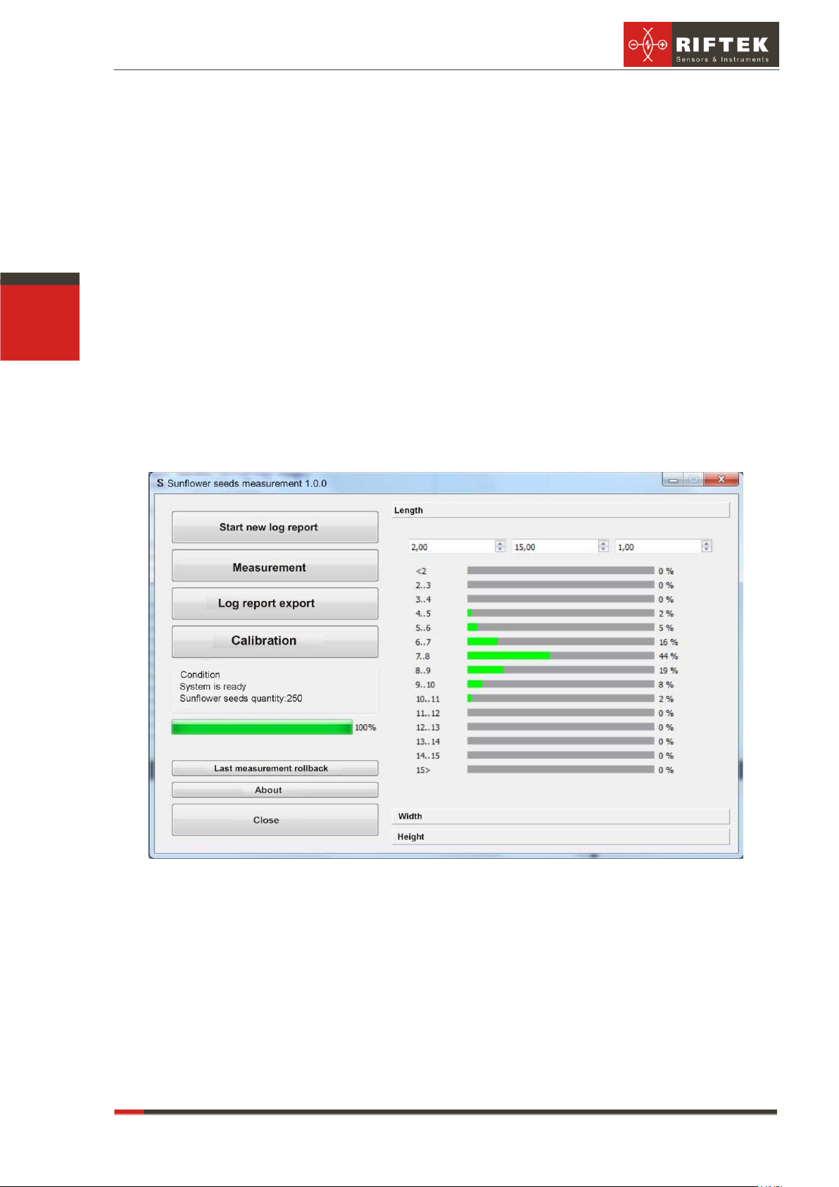
9.4. Calibration
For the first start of the machine and once a month it is recommended to cali-
brate the machine. To do this, remove all items from the working surface of the machine
table and click Calibration. When the system status changes (e.g., because of transpor-
tation, reassembly), calibration must be carried in a mandatory manner.
9.5. Indicating lights
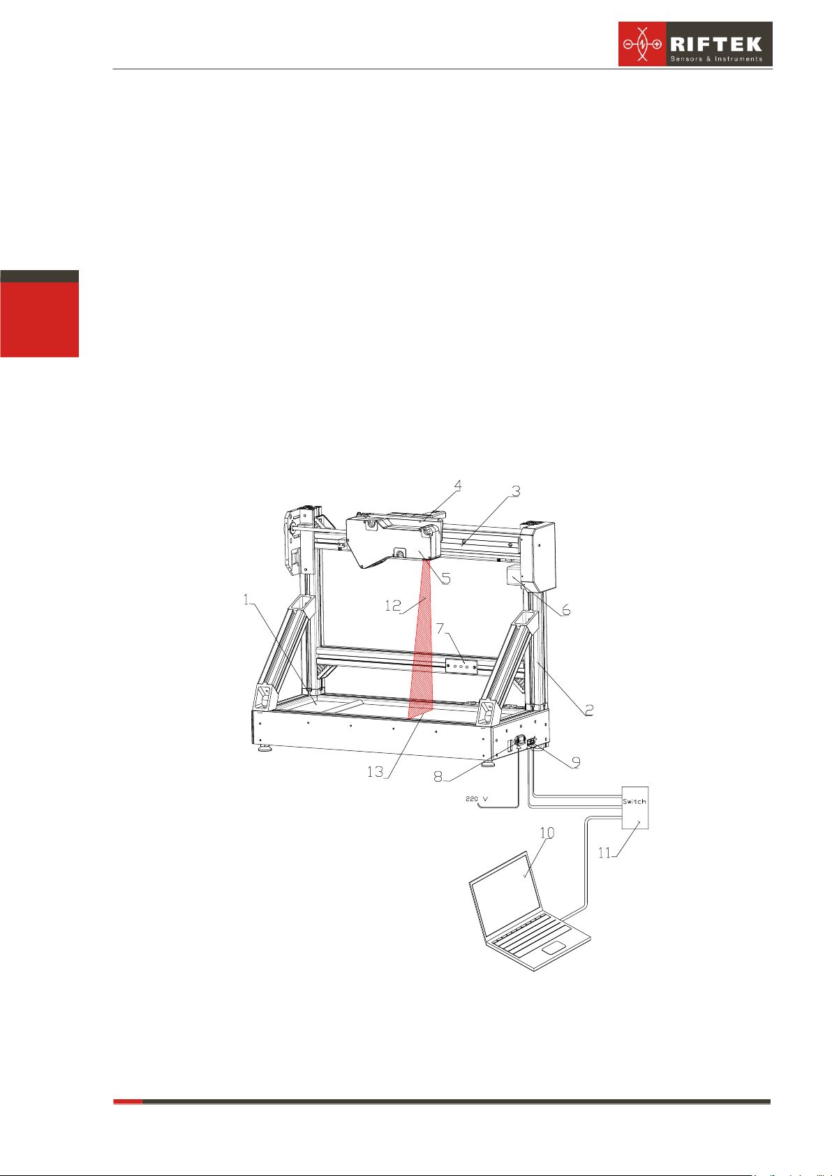
The indicating lights (see. Fig. 1) show the current status of the machine.
Red LED is lit –failure;
Blue LED is lit –machine is ready for operation
Yellow LED is lit –scanning is in process
10. Maintenance
10.1. General instructions
Maintenance of the machine is carried out to ensure constant-ready status and
continued availability of its work and to prevent premature failure.
10.2. Maintenance procedure
10.2.1.Daily maintenance work
Daily maintenance includes:
Visual inspection of the machine,
Checking of completeness,
Inspection of the units and elements that make up the machine,
Checking for any damage of the structural elements, power and instrument
cables, indicators and connectors,
weakening of screw connections and insulation failures,
Before starting work, it is necessary to wipe the input and output laser scan-
ner windows with a soft dry cloth.
10.2.2.Weekly maintenance work
Weekly maintenance includes:
cleaning of laser scanner windows with a dry soft lint-free cloth from contami-
nation or dirt;
checking of free movement of the carriage
10.2.3.Yearly maintenance work
Authenticated calibration of the laser scanner should be made once a year
11. Routine repairs
Trouble-shooting instructions are given in the following table.
Effects of extraneous illumination source
Remove extraneous illumination source
or protect the machine against its ef-
fects
Dirty laser scanner windows
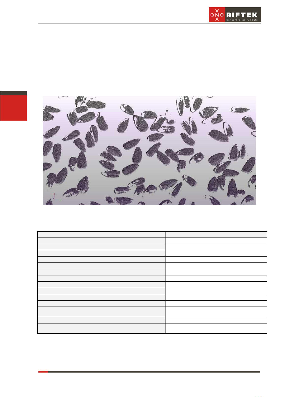
Seeds are in touch with each other
Fulfill condition in par. 8.1.