Riftek RF656XY-35 User manual

Certified according to ISO 9001:2008
SHAFTS GEOMETRY
MEASUREMENT MACHINE
22, Logoisky tract, Minsk
220090, Republic of Belarus
tel/fax: +375 17 281 36 57
info@riftek.com
User's manual
www.riftek.com
RF800 Series

2
Shafts Geometry Measurement Machine. RF800 Series
RF800 [Revision 1.0.0] 01.08.2018
Contents
.............................................................................................................................................31. Safety precautions
.............................................................................................................................................32. CE сompliance
.............................................................................................................................................33. Laser safety
.............................................................................................................................................34. General information
.............................................................................................................................................35. Structure and operating principle
........................................................................................................................................... 35.1. Optical micrometer
................................................................................................................. 45.1.1. Micrometer specifications
........................................................................................................................................... 55.2. Structure
........................................................................................................................................... 75.3. Operating principle
.............................................................................................................................................76. Basic technical data
.............................................................................................................................................87. Software
........................................................................................................................................... 87.1. Main window
........................................................................................................................................... 87.2. Settings ................................................................................................................. 97.2.1. Language ................................................................................................................. 107.2.2. Password ................................................................................................................. 107.2.3. Parameters................................................................................................................. 117.2.4. Operator ................................................................................................................. 117.2.5. Part .............................................................................................................. 127.2.5.1. Adding / editing the part template
.............................................................................................................. 147.2.5.2. Part template control
.............................................................................................................. 157.2.5.3. Saving the part template
................................................................................................................. 157.2.6. Workplace
........................................................................................................................................... 167.3. Calibration
.............................................................................................................................................178. Intended use
........................................................................................................................................... 178.1. Preparation for use
................................................................................................................. 188.1.1. Visual inspection
................................................................................................................. 188.1.2. Installation ................................................................................................................. 188.1.3. Switching on the machine
................................................................................................................. 188.1.4. Setting parameters and forming the database of templates
................................................................................................................. 188.1.5. Calibration ................................................................................................................. 188.1.6. Metrological verification
........................................................................................................................................... 188.2. Working with the machine
................................................................................................................. 198.2.1. Shafts of different diameters
................................................................................................................. 198.2.2. Shafts of different lengths
................................................................................................................. 198.2.3. Setting the origin of the linear coordinate
................................................................................................................. 218.2.4. Template selection
................................................................................................................. 228.2.5. Measurement
........................................................................................................................................... 268.3. Working with the database
.............................................................................................................................................289. Maintenance
........................................................................................................................................... 289.1. General instructions
........................................................................................................................................... 289.2. Safety precautions
........................................................................................................................................... 289.3. Maintenance procedure
................................................................................................................. 289.3.1. Daily maintenance work
.............................................................................................................. 289.3.1.1. Checking the loosening of screw connections
.............................................................................................................. 289.3.1.2. Optical signal quality control
................................................................................................................. 319.3.2. Annual maintenance work
.............................................................................................................................................3110. Warranty policy
.............................................................................................................................................3111. Revisions
.............................................................................................................................................3212. Distributors

RF800 [Revision 1.0.0] 01.08.2018
Shafts Geometry Measurement Machine. RF800 Series
3
1. Safety precautions
·
All specialists must study this User's Manual before operating the machine.
·
Use supplyvoltage and interfaces indicated in the machine specifications.
·
In connection/disconnection of cables, the power must be switched off.
·
Do not use the machine in locations close to powerful light sources.
·
To obtain stable results, wait about 20 minutes after powering the machine to
achieve the uniform warm-up of the micrometer.
·
During the measurement procedure, the protective doors of the machine must be
closed.
2. CE сompliance
The machine has been developed for use in industry and meets the requirements of
the following Directives:
·
EU directive 2014/30/EU. Electromagnetic compatibility (EMC).
·
EU directive 2011/65/EU, 'RoHS' category 9.
3. Laser safety
The machine contains an optical micrometer, which makes use of a LED. The
micrometer belongs to the 1 laser safety class. The following warning label is placed on the
housing:
The following safety measures should be taken while operating the micrometer:
·
Avoid staring into the emitter during a prolonged time period.
·
Do not disassemble the micrometer.
4. General information
The machine is designed to control the geometrical parameters of the 'shaft' type
parts. Field of application: large-scale production. Place of installation: production line, or
laboratory.
Technical characteristics of the machine can be changed for a specific task.
5. Structure and operating principle
5.1. Optical micrometer
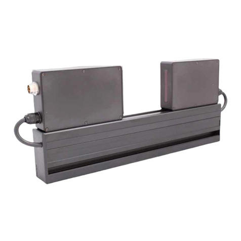
To measure the geometrical parameters of the 'shaft' type parts, a two-axis optical
micrometer is used.
The operating principle of the micrometer (for one axis) is illustrated in Figure 1.
The micrometer consists of two blocks: transmitter and receiver. Radiation of LED
1 is collimated by a lens 2. With an object placed in the collimated beam region, a shadow
image is formed by the telecentric system 3 on the CCD photodetector array 4. A
processor 5 calculates the diameter of the object from the position of shadow borders.

4
Shafts Geometry Measurement Machine. RF800 Series
RF800 [Revision 1.0.0] 01.08.2018
Figure 1
A two-axis optical micrometer contains two identical micrometers (in accordance
with the scheme in Fig. 1) in one housing, placed at an angle of 90 degrees to each other,
which makes it possible to control the diameter of the object in two mutually perpendicular
directions, Fig. 2.
Figure 2
5.1.1. Micrometer specifications
Optical micrometer, RF656XY-35 model
Measurement range, mm
±6х35
Minimum size of the object, mm
0.25
Maximum size of the object, mm
35
Accuracy, m
±1
Repeatability, m
0.5
Maximum scanning frequency, Hz
10000
Maximum update frequency, Hz
2000
Light source
LED
Lase safety class
1 (IEC60825-1)
Output interface
RS485
Synchronization input
2.4 – 5 V (CMOS, TTL)
Power supply, V
24 (9...36)
Power consumption, W
from 1.5 to 2
Environmental
resistance
Enclosure rating
IP67
Vibration
20 g / 10…1000 Hz, 6 hours for each of XYZ axes
Shock
30 g / 6 ms
Operating
ambient
temperature, °C
-10…+60
Relative humidity
5-95%
Housing material
aluminum
Weight (without cable), gram
1600
Dimensions
see the figure

RF800 [Revision 1.0.0] 01.08.2018
Shafts Geometry Measurement Machine. RF800 Series
5
5.2. Structure
The structure of the machine (without protective doors) is illustrated in Figure 3.
The machine contains a frame (1) on which a linear guide (2) of the linear translation
system is installed. The linear guide has a carriage (3) driven by a stepper motor (4).
An optical micrometer (5) is installed on the carriage (3). The end sensors (not
shown) are used to monitor the end positions of the micrometer. A table with two Morse
tapers (6 and 7) is used to install the controlled shaft. The Morse tapers are mounted on a
bar (8) located along the the linear guide. One of the end sensors is mounted on the upper
taper, the latter can be reinstalled along the bar (8) in order to control the shafts of different
lengths.In addition, the machine has a caliber, which is a part of the upper Morse taper. The
caliber is designed for an automatic re-calibration of the micrometer to eliminate the
measurement error caused by a change in the temperature of the machine.
The machine contains a mini-computer (9) with a graphic touch screen. The mini-
computer has the special software designed to control the machine and to display results.
The mini-computer can be built into the machine (as shown in Figure 3), or it can be
installed on the special stand (see Figure 4).
The back side of the machine has a power supply 220/24V (10) with a circuit
breaker (11), connector for the foot switch (12), USB connector (13) for the USB drive (for
example, for data transfer), and the Ethernet connector (14), for example, to connect to the
PC.

6
Shafts Geometry Measurement Machine. RF800 Series
RF800 [Revision 1.0.0] 01.08.2018
Figure 3
Figure 4

RF800 [Revision 1.0.0] 01.08.2018
Shafts Geometry Measurement Machine. RF800 Series
7
5.3. Operating principle
After the measurement algorithm has been programmed (position and number of
controlled zones along the shaft, tolerances, etc. - see the software description), the
operator installs a shaft into the machine. After a command from the operator (by the foot
switch, or by the softkey on the touch screen), the linear translation system moves the
micrometer along the shaft. The data from the micrometer (shaft diameters in two mutually
perpendicular cross sections) synchronized with the linear position of the micrometer
comes to the computer where the required parameters are calculated (shaft diameter and
shaft shape error).
6. Basic technical data
Parameter
Value
Shaft length, mm
160...750
Shaft diameter, mm
5...30
Accuracy, m
±1
Time of measuring the shaft of the
maximum length, s, no more than
20
Number of controlled shaft zones and their
position
Programmable value
Maximum shaft weight, kg
2
Measured parameters
Diameter, ovality, taper
Sorting "OK"-"NOK"
Yes
Ability to sort by groups
Yes
Power supply
Three-phase alternating current network with frequency of (50 ±
1) Hz, nominal voltage 220 / 380V with a permissible voltage
deviation of ±10%.
Power consumption, W
100
Environmental resistance
Operating ambient temperature: +1...+35°С
Relative humidity for 25°С: 65%
Operation mode
3 shifts, 6 days a week
Dimensions, mm
380х428х1079
Note: Machine parameters can be changed for a specific task

8
Shafts Geometry Measurement Machine. RF800 Series
RF800 [Revision 1.0.0] 01.08.2018
7. Software
7.1. Main window
After the machine is powered on, the software is loaded and the main window
appears.
Button
Assignment
Settings
Set the measurement parameters.
Calibration
Perform the calibration procedure.
Measurement
Control the measurement process.
Database
View the database.
7.2. Settings
Only qualified users are allowed to change settings, so when you tap the Settings
button, you will need to enter a password (by default: 1111).
Enter the password and tap Ok. The Settings window appears:

RF800 [Revision 1.0.0] 01.08.2018
Shafts Geometry Measurement Machine. RF800 Series
9
The parameters menu is located in the left part of the window. The arrow in the
upper left corner is used to go back to the previous window.
7.2.1. Language
To select the language, tap Language. The following window appears:
Select the language and tap Save.

10
Shafts Geometry Measurement Machine. RF800 Series
RF800 [Revision 1.0.0] 01.08.2018
7.2.2. Password
To change the password, tap Password. The following window appears:
Enter a new password and confirm it (the toggles in the fields are used to show/hide
the entered characters). Tap Save.
7.2.3. Parameters
To change parameters, tap Parameters. The following window appears:
Parameter
Default
value
Note
COM port
3
The COM port number of the internal RS485 network.
This parameter can be changed only by the manufacturer.
Baud rate, bit/s
115200
The baud rate of the COM port.
This parameter can be changed only by the manufacturer.
Number of decimals
3
The displayed number of decimals.
Part type
Shaft
This parameter is selected in accordance with the device type: Shafts
control - 'Shaft', Holes control - 'Hole'.

RF800 [Revision 1.0.0] 01.08.2018
Shafts Geometry Measurement Machine. RF800 Series
11
Parameter
Default
value
Note
Calibration diameter D
20 mm
The diameter of the caliber installed in the Morse taper (see p. 5.2.).
Tolerance for
calibration
0.002 mm
This tolerance is used when testing the calibration accuracy (see p.
7.3.).
Motor step
453
Linear displacement of the micrometer, which corresponds to one step
of the motor.
This parameter can be changed only by the manufacturer.
To save changes, tap Save.
7.2.4. Operator
Tap Operator. The following window appears:
In this window, you can select, edit, delete, or add the new operator.
7.2.5. Part
In the program, the measured parts are shown as templates described by the
following parameters: the position of the controlled zone on the shaft, its size and diameter,
and the tolerances for sorting. The number of zones is up to 8. To set the template
parameters, tap Part. The following window appears:

12
Shafts Geometry Measurement Machine. RF800 Series
RF800 [Revision 1.0.0] 01.08.2018
In this window, you can see a list of controlled shafts with their unique numbers and
names. Parameters of the selected shaft are shown in the table (the selected shaft is
highlighted in blue in the list to the left).
The description of parameters:
Name
Description
A
The position of the controlled zone on the shaft.
L
The length of the controlled zone.
Gr0...Gr4
Sorting groups (diameter value ± tolerance).
QC
Quality control sign.
7.2.5.1. Adding / editing the part template
To add the part template to the list, tap Add. To edit the part template, tap Edit. The
following window appears:
Enter a decimal number of the part, its description and length into the respective
fields. To form the controlled zones, tap . "Diameter 1" appears in the List:
Select the diameter (D1...D8) from the Name drop-down list.

RF800 [Revision 1.0.0] 01.08.2018
Shafts Geometry Measurement Machine. RF800 Series
13
Enter the diameter value and the tolerance value into the Diameter field and the
Tolerance field respectively. Enter the parameters of the controlled zone, namely, the
position of the zone on the shaft (Size A) and the zone length (Size L). In addition, it is
necessary to enter the number of controlled sections (Sections d): 2 or 3. When "2" is
selected, the measurements are performed in two sections spaced from the edges of the
zone for 3 mm. When "3" is selected, an additional measurement is made in the center of
the zone. The diameter of the zone is calculated as the average diameter measured in the
selected sections. The cylindricity value of the zone is calculated as the difference in
diameters measured at the edges of the zone.
If it is necessary to divide the measured parts into groups, tap on the Group toggles
and enter the diameter value and the tolerance value for each group.
These tolerances are also used to control the ovality and taper of the zone.
Enter the required number of zones and their parameters in accordance with the
algorithm described above.
If the diameter is controlled only by the quality control department, tap on the QC
toggle to enable it. The groups will be hidden.

14
Shafts Geometry Measurement Machine. RF800 Series
RF800 [Revision 1.0.0] 01.08.2018
7.2.5.2. Part template control
To control the part template, tap .
This window displays the part template with the controlled zones. The proportions of
the zones correspond to their size. To go back to the template creation window, tap .

RF800 [Revision 1.0.0] 01.08.2018
Shafts Geometry Measurement Machine. RF800 Series
15
7.2.5.3. Saving the part template
To save the part template, tap Save. The program returns to the list of controlled
parts and displays the parameters of the saved template.
7.2.6. Workplace
The machine can be installed on workplaces of various types (production line,
quality control department). On production lines, only one selected zone is measured at
each workplace. During the quality control, the whole shaft is measured without sorting into
groups) To set the workplace type and its description, tap Workplace.
The list of workplace numbers is shown in the left side of the window.
The workplace number of the machine is marked with .
Description of the workplace (in the right side of the window) is given for the
workplace number highlighted in blue in the list to the left.
If the QC toggle is enabled, this workplace relates to the quality control department,
and the measurements are performed in full (without sorting into groups).
To describe the workplace (not QC), disable the QC toggle and follow the steps
below:

16
Shafts Geometry Measurement Machine. RF800 Series
RF800 [Revision 1.0.0] 01.08.2018
·
Select (Select button), or add (Add button), and then select the workplace
number.
·
Select the controlled diameter from the Diameter drop-down list.
·
Describe the workplace in the Description text box.
7.3. Calibration
To perform the calibration of the machine, go to the main menu and tap
Calibration.
Select the shaft that will be used as the caliber. Tap Accept. The program displays
the description of the selected shaft.
Install the shaft into the machine, and tap Calibration. The shaft will be scanned. If
necessary, parameters of the optical micrometers will be corrected automatically, and then
the shaft will be scanned again in order to test the machine. If successful, the following
window appears:

RF800 [Revision 1.0.0] 01.08.2018
Shafts Geometry Measurement Machine. RF800 Series
17
The Deviation column shows the difference between the actual value and the
measurement result. The calibration is successful if the deviation value doesn't exceed the
tolerance (Tolerance for calibration, see par. 7.2.3.).
If the calibration is not successful, the following window appears:
Zones, in which the measurement result exceeds the tolerance, are shown in red.
Repeat the calibration procedure until you see the message informing about
success.
8. Intended use
8.1. Preparation for use
Preparation of the machine includes:
·
visual inspection,
·
installation,
·
switching on the machine,
·
setting parameters and forming the database of templates,
·
calibration of the machine,
·
metrological verification of the machine.

18
Shafts Geometry Measurement Machine. RF800 Series
RF800 [Revision 1.0.0] 01.08.2018
8.1.1. Visual inspection
Before operating, it is needed to ensure of the serviceability of the machine:
·
check the cables and ground wires,
·
check the condition of output windows of the micrometer, and, if necessary, wipe
them with a soft lint-free cloth.
8.1.2. Installation
Install the machine on the equipment. Connect the power cable (220V).
8.1.3. Switching on the machine
Feed power to the machine by switching on the circuit breaker, see Figure 3.
8.1.4. Setting parameters and forming the database of templates
Set parameters in accordance with p. 7.2. Form the database of templates in
accordance with p. 7.2.5.
8.1.5. Calibration
Calibrate the machine in accordance with p. 7.3. The calibration procedure must be
performed:
·
daily before the work shifts,
·
in case of changing the shaft type,
·
if the position of the machine was changed.
8.1.6. Metrological verification
Metrological verification of the machine must be performed:
·
before commissioning,
·
after repair,
·
periodically during operation.
8.2. Working with the machine
The measurement of geometrical parameters is fully automated and the work with
the machine is reduced to the mechanical adjustment, and then to the work with the
software. Follow the steps below:
·
Configure the machine to operate with the shaft of the appropriate diameter, see
par. 8.2.1.
·
Configure the machine to operate with the shaft of the required length, see par.
8.2.2.
·
Start the software, see par. 7.
·
Install the controlled shaft into the machine.
ATTENTION: It is necessary to clean the shaft from cutting fluid and oil before
installing into the machine!
·
Tap the Measurement button.

RF800 [Revision 1.0.0] 01.08.2018
Shafts Geometry Measurement Machine. RF800 Series
19
8.2.1. Shafts of different diameters
The machine is equipped with the Morse tapers of two types: a small taper and a
big taper (see Figure 5 and Table 5 in Catalog RF800.00.000, items 7 and 8). To replace
the tapers, it is necessary to: unscrew the calibers, get the tapers, tighten the calibers,
install the new tapers.
8.2.2. Shafts of different lengths
To measure the shafts of different lengths, the machine is adjusted by moving the
upper rack of the Morse taper with the end sensor fixed to it along the table (see Figure 5 in
Catalog RF800.00.000).
8.2.3. Setting the origin of the linear coordinate
After you replace the support taper, it is necessary to set the origin of the linear
coordinate.
The upper end sensor, installed on the movable Morse taper, specifies the origin of
the linear coordinate of the linear translation system (the coordinate of the starting position
of the micrometer). In the starting position, the micrometer must be positioned so that the
caliber (the part of the Morse taper) is placed within the measurement zone of the
micrometer.
Follow the steps below:
1. Start RF701_Controller.exe, which is in the Riftek install \RF701_Controller
directory on the desktop of the mini-PC.
2. In the Settings menu, select a port: COM4.
3. Select Connection > Connect in order to connect to the system.

20
Shafts Geometry Measurement Machine. RF800 Series
RF800 [Revision 1.0.0] 01.08.2018
4. Tap the GoToEnd button in order to move the micrometer to the lowest position.
5. Install the rack 3 (see Figure 4 in Catalog RF800.00.000) at the highest position.
6. Install the shaft into the machine. ATTENTION: the shaft must be installed!
7. Tap the GoToZero button in order to move the micrometer to a zero position.
The caliber must be on the beam axis of the micrometer.
The figure below illustrates the incorrect position of the micrometer:
The figure below illustrates the correct position of the micrometer:
This manual suits for next models
1
Table of contents
Other Riftek Measuring Instrument manuals

Riftek
Riftek RF089 Series User manual

Riftek
Riftek IMR Series User manual

Riftek
Riftek IDK Series User manual

Riftek
Riftek RF1010SL Series User manual

Riftek
Riftek RF651 Series User manual

Riftek
Riftek IMR-L Series User manual

Riftek
Riftek RF096-32/42-80 Series User manual

Riftek
Riftek RF096-100/250-87-HH Series User manual

Riftek
Riftek RF096-30/75-120 User manual

Riftek
Riftek IMR Series User manual