Riftek IDK-BT Series User manual

Certified according to ISO 9001:2008
WHEEL DIAMETER MEASURING GAUGE
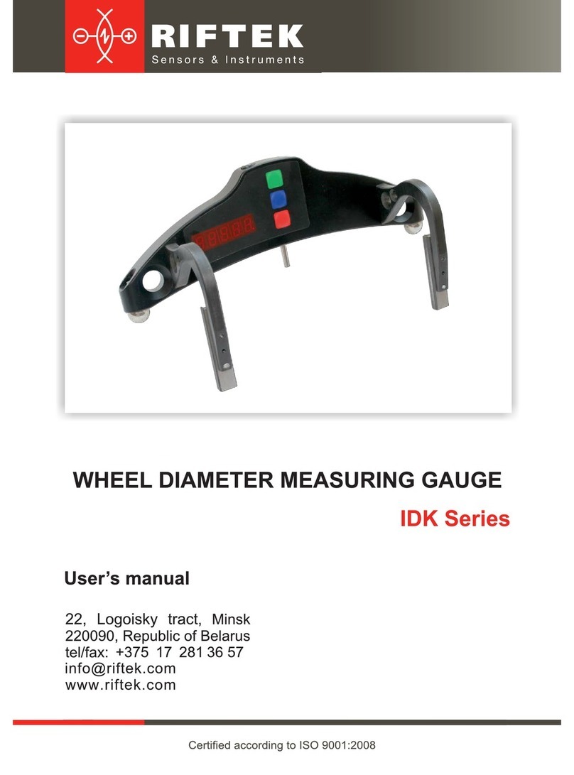
IDK-BT Series
22, Logoisky tract, Minsk
220090, Republic of Belarus
tel/fax: +375 17 357 36 57
www.riftek.com
User’s manual

Wheel diameter measuring gauge, IDK-BT
IDK-BT [Revision 2.2] 4th September 2017
2
Contents
1. Safety precautions and measurement conditions..................................................................................3
2. Electromagnetic compatibility.................................................................................................................3
3. General information................................................................................................................................3
4. Basic data and performance characteristics..........................................................................................3
5. Example of item designation when ordering..........................................................................................4
6. Complete set to be supplied...................................................................................................................4
7. Design....................................................................................................................................................5
7.1. Electronic gauge............................................................................................................................5
7.2. Indication device (option) ..............................................................................................................5
8. Operation principle.................................................................................................................................7
9. Working with the gauge and working in autonomous regime ................................................................7
9.1. Gauge turn-on ...............................................................................................................................7
9.2. Single measurement......................................................................................................................7
9.3. Measurement with averaging ........................................................................................................8
9.4. Gauge turn-out ..............................................................................................................................8
10. Indication parameters setup...................................................................................................................8
10.1. Bluetooth ON/OFF.........................................................................................................................8
10.2. Image rotation................................................................................................................................9
10.3. Image brightness set-up..............................................................................................................10
10.4. Millimeters-Inches -Tapes display set-up....................................................................................10
11. Service operation modes .....................................................................................................................11
11.1. Calibration conditions..................................................................................................................11
11.2. Get into operational modes .........................................................................................................11
11.3. Calibration of the sensor zero .....................................................................................................11
11.4. Calibration of the device base.....................................................................................................12
12. Working with the gauge and PDA........................................................................................................13
12.1. Operation principle ......................................................................................................................13
12.2. Gauge and PDA activation..........................................................................................................13
12.2.1. Gauge turn-on ........................................................................................................................13
12.2.2. PDA turn-on............................................................................................................................13
12.3. On-line measurement..................................................................................................................14
12.4. Measurements with database maintenance................................................................................15
12.5. Browsing the database................................................................................................................16
12.6. Saving database on flash memory card......................................................................................17
13. PDA program setting............................................................................................................................17
13.1. Selection of measurement units..................................................................................................17
13.2. Data and Time settings................................................................................................................18
13.3. Tolerances settings .....................................................................................................................18
13.4. Database selection......................................................................................................................19
13.5. Selection and formation of measurement scheme......................................................................20
13.5.1 Selection or removal of the measurement scheme.................................................................20
13.5.2 Formation of a new measurement scheme.............................................................................20
13.5.3 Loading of a new measurement scheme ................................................................................21
13.6. New electronic gauge connection ...............................................................................................21
13.7. Selection and changing of language and terminology ................................................................21
13.7.1 Preparation and installation of language support file ..............................................................21
13.8. PDA software version viewing.....................................................................................................22
13.9. Deactivation.................................................................................................................................22
14. Working with the gauge and PC...........................................................................................................22
14.1. Program starting..........................................................................................................................22
14.2. IDK-PC connection......................................................................................................................23
14.3. Measurement...............................................................................................................................23
15. Database maintenance software .........................................................................................................24
16. Charging of built-in accumulator battery ..............................................................................................24
17. Warranty policy.....................................................................................................................................24
18. Annex 1. Procedure of installation of Bluetooth connection between IDK and PC..............................24
19. Distributors...........................................................................................................................................28
20. Annex 2. RIFTEK’s measurement devices for railway transport .........................................................31
Wheel diameter measuring gauge, IDK-BT
IDK-BT [Revision 2.2] 4th September 2017
3
1. Safety precautions and measurement conditions
The metering accuracy depends greatly on the wheel surface quality. There-
fore it is necessary to carry out the check and presorting of the wheel surface
roughness and flaws before measuring the diameter.
Prior to place the gauge onto the wheel there is a need to clean the wheel
parts that contact with gauge ball bearings, side supports and measuring tip,
of the mud.
At arranging the gauge, do not allow hitting its supports on the wheel and any
measuring tip side hitting
At arranging the gauge, do not apply strong forcing in the direction of the
measuring tip movement. It can result in the gauge sag, that will bring about
the uncertain metering result
It is necessary to inspect the gauge supports periodically and to cleanse them
To save the battery power the display extinguishes if there were no buttons
pressings for 60 seconds, at that only blinking dot is shown. Pressing any but-
ton just turns on the display and does not act in any other way in this case.
2. Electromagnetic compatibility
The gauge has been developed for use in industry and meets the requirements
of the following standards:
EN 55022:2006 Information Technology Equipment. Radio disturbance char-
acteristics. Limits and methods of measurement.
EN 61000-6-2:2005 Electromagnetic compatibility (EMC). Generic standards.
Immunity for industrial environments.
EN 61326-1:2006 Electrical Equipment for Measurement, Control, and Labor-
atory Use. EMC Requirements. General requirements.
3. General information
Electronic gauge is designed for measuring wheel rolling circle diameter (amount
of wear) of railway, metro and tram in the course of checkup, examination, repair and
formation of wheel sets. Measurements are made directly on rolling stock without wheel
set roll-out.
4. Basic data and performance characteristics
Name of parameter
Value
Measurement range, mm
400…1400 or on request
Measurement error, mm
±0.2
Indication discreteness
0.1mm, 0.01mm * or 0.01 inch **
Position of measurement, S, mm
On request
Distance between axes of ball bearings (base), mm
and measurement range, mm
122±0.5 (400…750 mm) or
200±0.5 (400…950 mm) or
250±0.5 (600…1400 mm) or
300±0.5 (720…1400 mm)
Display
build-in, LED
Operating temperature, 0C
-5…+55
Power supply –built-in rechargeable battery
two AAA 1,2V
The number of measurements that can be taken before battery recharge is
not less than
1000
Weigh, kg
0,5

Wheel diameter measuring gauge, IDK-BT
IDK-BT [Revision 2.2] 4th September 2017
4
5. Example of item designation when ordering
IDK-S/B-MIN/MAX-X-BT
Symbol
Description
S
Position of measurement, mm
В
Base, mm
MIN
Bottom of measuring range, mm
MAX
Up of measuring range, mm
Х
Position of indication. А – Indication is at the side of side supports (figure А), В
–Indication is at opposite side (figure В)
BT
Bluetooth presence*
* The gauge with Bluetooth can work in autonomous regime and together with RF303 PDA or PC, with
measurements saving in database.
Example: IDK-70/250-850/1260-А-BT.Position of measurement –70 mm; base of the
gauge –250 mm; bottom of measuring range –850 mm; up of measuring range –1260
mm; position of indication –А, BT –Bluetooth presence .
Fig.А
Fig.В
6. Complete set to be supplied
Name
Quantity
Weight, kg
Wheel diameter measuring gauge IDK series
1 piece
0,5
Charger
1 piece
0,2
RF303 –PDA (option)
1 piece
0,4
Charging device 5V 3.0A for PDA (option)
Manual
1 piece
Case
1 piece
Database management system (CD)
Calibration tools (option)
on request
Flat block RF510.11.000 (fig.4)
-
Reference wheel block for calibrating RF510.11.850 (fig.5)
-

Wheel diameter measuring gauge, IDK-BT
IDK-BT [Revision 2.2] 4th September 2017
5
7. Design
7.1. Electronic gauge
The gages with bases of 200, 250 and 300 mm are shown on the Figure 1, the
gage with base of 122 mm –on Figure 1.1. Electronic gauge contains two ball supports
to place the gauge onto the roll surface, two side magnet supports to base the gauge to
the wheel edge and a measuring tip.
There are a digital numeric display and control buttons on the front panel of the
gauge. “Charge” connector for charging device connection and Bluetooth indication LED
are situated on the top panel of the gauge.
Figure 1
Figure 1.1
7.2. Indication device (option)
PDA is designed for control of the laser scanning module, data reception from
the scanning module, indication of measurement results, parameter input and data stor-
age.

Wheel diameter measuring gauge, IDK-BT
IDK-BT [Revision 2.2] 4th September 2017
6
Figure 2
Fig. 2 indicates:
(1) Turn-on button
(2) Charging indication, red/blue LED
(3) Connector to PC USB-port or charging device
(4) Flash memory card connector
(5) Stylus
(6) Bluetooth antenna
Overall dimensions of PDA are shown in figure 3.
Figure 3

Wheel diameter measuring gauge, IDK-BT
IDK-BT [Revision 2.2] 4th September 2017
7
8. Operation principle
The measurement of the diameter is performed according to the “three points”
technique, without the complete wheel coverage. The measurement method is based on
the diameter calculation by the known length of the segment chord (the distance be-
tween the ball bearings centers), which is obtained at placing the gauge onto the wheel.
The suggita of the segment is measured by means of the displacement converter. Video
presentation is placed here: https://youtu.be/pMienHfBizg
9. Working with the gauge and working in autono-
mous regime
9.1. Gauge turn-on
Press Red button to turn on the power. The display shows “ErrP” message if the
accumulator battery voltage became lower then the control level. In this case the short-
term work is possible after pressing any key.
9.2. Single measurement
To perform measurement, it is necessary to:
turn the power on (press Red button). The display shows “- - - - -”;
place the gauge onto the wheel;
make sure the ball supports are tight against the roll surface and side sup-
ports are adjacent to the edge of the wheel;
press Green button.
in a 1 second the display will show the value of the wheel diameter.
For viewing the result of measurement with indication discreteness of 0.01mm (it
is accessible only in a mode of direct indication) it is necessary to press Blue button,
thus displayed result will be shifted to the left on one digit. Next pressing Blue button will
lead to return of indication to a starting position:

Wheel diameter measuring gauge, IDK-BT
IDK-BT [Revision 2.2] 4th September 2017
8
9.3. Measurement with averaging
The program of the wheel diameter calculation contains an averaging algorithm
that allows eliminating the surface defects influence on the diameter measuring result.
All the results of metering, performed after the Red button pressing, are averaged. The
measurement is meant to be Green button pressing.
To carry out measurements it is necessary to
turn the power on (press Red button). The display shows “- - - - -”;
place the gauge onto the wheel
make sure the ball supports are tight against the roll surface and side sup-
ports are adjacent to the edge of the wheel;
press Green button;
display shows the value of pressing counter “n x”, where x–quantity of av-
eraged values;
in a 1 second display shows an average value over the set of metering (over
the quantity of Green button pressings)
move the gauge to a new position and repeat the measuring.
(The total quantity of measurements averaged in this way can run up to 9999.)
Press Red button to reset averaging result at switching to another wheel.
For viewing the result of measurement with indication discreteness 0.01mm (it is
accessible only in a mode of direct indication) it is necessary to press Blue button, thus
displayed result will be shifted to the left on one digit. Next pressing Blue button will lead
to return of indication to a starting position.
9.4. Gauge turn-out
The gauge turn-out occurs automatically. The display extinguishes if there were
no buttons pressings for 60 seconds, at that only blinking dot is shown. If there were no
button pressings for 4 more minutes, the gauge is turned out completely. You can turn
the gauge off by long pressing Red button (more then 3 sec.).
10. Indication parameters setup
10.1. Bluetooth ON/OFF
To switch Bluetooth ON it is necessary to:
turn the power on
press Blue button and keep it pressed for more than three seconds
display will show “bt On”
to turn Bluetooth off press Green button. Display will show “bt OF”

Wheel diameter measuring gauge, IDK-BT
IDK-BT [Revision 2.2] 4th September 2017
9
to save the changed parameters press Red button. The display shows
“SAUE” message, press the Green button to confirm saving and Red button
to cancel saving of the changed parameters
10.2. Image rotation
To rotate the image it is necessary to:
turn the power on (press Red button);
press Blue button and keep it pressed for more than three seconds;
display will show "bt On"or " bt OF";
press Blue button again. Display will show "“Up”
by the pressing of Green button turn over the image: the message “Up” will
be turned over 1800;
to save the changed parameters press Red button. The display shows
“SAUE” message, press the Green button to confirm saving and Red to can-
cel saving of the changed parameters;
Image rotation function allows observing the result in the way comfortable for the
operator regardless of the gauge placement direction.
Notes:

Wheel diameter measuring gauge, IDK-BT
IDK-BT [Revision 2.2] 4th September 2017
10
- indication discreteness of 0.01mm is accessible only in a mode of direct indica-
tion; - the separation point is indicated at the top side of the screen in the reverse indica-
tion regime.
10.3. Image brightness set-up
To change the display brightness it is necessary to:
turn the power on (press Red button).;
press Blue button and keep it pressed for more than three seconds;
display will show "bt On"or " bt OF";
press Blue button again until “brt X” message appears on the display;
choose the necessary brightness value by Green button pressings;
to save the changed parameters press Red button the display shows “SAUE”
message, press the Green button to confirm saving and Red to cancel saving
of the changed parameters;
At brightness choosing one should take into account that increased brightness
enhances power consumption and decreases the period till battery recharge moment.
10.4. Millimeters-Inches -Tapes display set-up
To change the mode it is necessary to:
turn the power on (press Red button).;
press Blue button and keep it pressed for more than three seconds;
display will show "bt On"or " bt OF";
press Blue button again until the either “SI” or “Inch”or “Tape”message ap-
pears on the display. “SI” –measuring results will be shown in mm, “Inch” –
measuring results will be shown in inches; “Tape” –measuring results will be
shown in tapes.
choose the necessary value by Green button pressings;

Wheel diameter measuring gauge, IDK-BT
IDK-BT [Revision 2.2] 4th September 2017
11
to save the changed parameters press Red button the display shows “SAUE”
message, press the Green button to confirm saving and Red to cancel saving
of the changed parameters
11. Service operation modes
This section contains the description of the modes for the check of device effi-
ciency and calibration. As erroneous actions in this mode can lead to invalid measure-
ment results, only specially trained personnel should perform such operations.
11.1. Calibration conditions
Calibration of the device is not necessary in the current work. It is neces-
sary only after producing, repairing and also after checking with negative result.
To perform calibration the following means are necessary:
Calibration plate with the deviation from flatness less then ±0,5 um for 250
mm length (or Flat block RF510.11.000, figure 4);
Johansson gauge;
reference wheel of the known diameter (or Reference wheel block
RF510.11.850, figure 5)
11.2. Get into operational modes
To get into the operational modes it is necessary to turn-off the device (press
Red button more then 3 seconds).
Keeping Green button in pushed position turn-on the device (press Red but-
ton).
Display shows “CLbr.0” message (the mode of calibration of the sensor's "0").
To get into this mode it is necessary to press Green button (see. p. 11.3).
For transition to next mode it is necessary to press Blue button.
Display shows “CLbr.b” message (the mode of device base calibration).
To get into this mode press Green button (see. p.11.4).
To get out the mode of calibration press Red button.
11.3. Calibration of the sensor zero
When zero calibration mode being enabled, the display shows the Johansson
gauge value used for calibration in increments of 0.5 µm.
If editing of the Johansson gauge value is not required, go to the next step. To
edit the Johansson gauge value, press the Blue button, and the digit to be ed-
ited starts blinking. Changing over between the digits is made by pressing the
Blue button while changing of values is made by pressing the Green button.
When editing is finished, press the Red button and confirm or cancel saving of
the parameter by pressing the Green button or Red button, respectively.
Press the Green button, and the Johansson gauge value starts blinking,
which means that the device must be placed onto a flat plate and a Johans-
son gauge with nominal value of the previous step must be placed under the
measuring tip. The Johansson gauge must be tightly fitted to the flat plate and
supports and balls of the device must be firmly forced against the plate.
Press the Green button, and the display shows current reading of the sensor
in its own coordinate system. By moving the device, assure that repeatability
of measurement results is obtained.

Wheel diameter measuring gauge, IDK-BT
IDK-BT [Revision 2.2] 4th September 2017
12
RF510.11.000
Figure 4
If readings of the sensor are sufficiently stable, press the Blue button. Sensor
zero position is calculated in the device coordinate system, and prompt ap-
pears to save calibration results. Press the Green or Red button to confirm or
cancel saving of the results, respectively.
11.4. Calibration of the device base
Device base calibration mode being enabled, the display shows the value of
reference diameter used for calibration.
If editing of the diameter value is not required, go to the next step. To edit the
diameter value, press the Blue button, and the digit to be edited starts blink-
ing. Changing over between the digits is made by pressing the Blue button
while changing of values is made by pressing the Green button. When editing
is finished, press the Red button and confirm or cancel saving of the parame-
ter by pressing the Green button or Red button, respectively.
Press the Green button, and the reference diameter value starts blinking,
which means that the device must be placed onto a gage with the diameter
value set at the previous step. The device supports must be firmly forced
against the reference block.
Press the Green button, and the display shows current reading of the sensor
in the device coordinate system. By moving the device, assure that repeatabil-
ity of measurement results is obtained.
If readings of the instrument are sufficiently stable, press the Blue button. De-
vice base value is calculated, and prompt appears to save calibration results.
Press the Green or Red button to confirm or cancel saving of the results, re-
spectively.

Wheel diameter measuring gauge, IDK-BT
IDK-BT [Revision 2.2] 4th September 2017
13
RF510.11.XXXX
Figure 5
NOTE: Video-help for calibration procedure you can find here
www.riftek.com/resource/video/idk_calibr.avi
12. Working with the gauge and PDA
12.1. Operation principle
Operator mounts the gauge onto the wheel to be measured. Having received a
command from PDA, the gauge performs the measurement of the wheel diameter.
Measurement result is displayed on PDA, can be saved in the PDA memory, and trans-
ferred to the PC database. Simultaneously, additional parameters can be saved: opera-
tor number, side identifier (left or right wheel), axis number, locomotive (carriage) num-
ber, wheel pair number, etc.
12.2. Gauge and PDA activation
12.2.1. Gauge turn-on
Press Red button to turn on the power. The display shows “ErrP” message if the
accumulator battery voltage became lower then the control level. In this case the short-
term work is possible after pressing any key.
12.2.2. PDA turn-on
Turn the PDA on by pressing the button (1), Fig. 2. Activation indication (2) will
show a green LED lit.
After the PDA is switched on, some time will pass until automatic wireless
communication is set between the gauge and the PDA, which is accompanied by
blinking of a blue LED (1) on the diameter gauge. The LED goes out when the link is
established.
The PDA screen will show the main program window containing: main menu;
indicators of PDA charging degree; indicator of Bluetooth connection showing serial
number of the gauge with which connection is established and the Measurement button.

Wheel diameter measuring gauge, IDK-BT
IDK-BT [Revision 2.2] 4th September 2017
14
12.3. On-line measurement
To take measurements:
turn-on the gauge, the display shows —“- - - - -”;
turn-on PDA;
press Measurement button on the screen of PDA; PDA is activated in
measurement regime and display shows:
place the gauge onto the wheel;
make sure the ball supports are tight against the roll surface and side sup-
ports are adjacent to the edge of the wheel;
press Green button. (Note: hereinafter, the button, marked by green or red
color is a corresponding button on the gauge or PDA screen). In a 1 second
the displays of the gauge and PDA will show the value of the wheel diameter.
When the diameter goes beyond set limits its value is highlighted with red col-
or:
"Measurement"
button
Menu
PDA charging
Bluetooth connec-
tion with the gauge
#02010

Wheel diameter measuring gauge, IDK-BT
IDK-BT [Revision 2.2] 4th September 2017
15
Buttons:
- diameter measurement
- averaging reset
to continue the measurement with averaging:
press Green button;
display shows the value of pressing counter “n x”, where x–quantity of av-
eraged values;
in a 1 second display shows an average value over the set of metering (over
the quantity of Green button pressings)
move the gauge to a new position and repeat the measuring. (The total quan-
tity of measurements averaged in this way can run up to 9999.)
Press Redbutton to reset averaging result at switching to another wheel.
12.4. Measurements with database maintenance
A fully functional work with the gauge involves maintenance of the measure-
ments database.
To take measurements:
select in the main menu Profilometer > Measurement, the window of pa-
rameters input will appear
If necessary, fill in/edit the required fields
to save parameters, press the Save button, and the program will offer the se-
lected measurement scheme (see par.13.5.):

Wheel diameter measuring gauge, IDK-BT
IDK-BT [Revision 2.2] 4th September 2017
16
Designations:
- order number of the car to be measured (number of cars in the
train);
- number of the car to be measured;
- editing of the input wheel parameters;
- a previous/subsequent wheel;
- a measured wheel;
- a wheel to be measured next time;
- a non-measured wheel;
- a measured wheel to be measured again
- measurement.
Measure the wheel offered by the program (highlighted in green color), as it is
shown in par. 12.3.
after the measurement, the PDA will show the value of diameter. When a diameter falls
out of the specific tolerance, its value is indicated with red color
when a satisfactory result is obtained, press Save on the display to save it
the program will offer to pass to measurement of the next wheel in accordance
with selected scheme of measurement
12.5. Browsing the database
To browse the database:
select Service > Profiles in the main window. View on the screen

Wheel diameter measuring gauge, IDK-BT
IDK-BT [Revision 2.2] 4th September 2017
17
for data filtering select data, series and number of locomotive
Buttons:
–delete selected data
12.6. Saving database on flash memory card
One of the ways to transfer database from PDA to PC is to use flash memory
card. To save database on the card, proceed as follows:
connect cable RF505.42 to the PDA universal connector
insert flash card to the respective cable connector
select Device > Save to USB flash in the main program window
if saving is successful, the screen will show Data saved on USB Flash
remove flash card from the cable
13. PDA program setting
Prior to starting work with the gauge, PDA program setting must be performed.
13.1. Selection of measurement units
All parameters as well as measurement results can be presented in the metric
system (millimeters) or in the English system of units (inches). To set measurement
units, it is necessary to
select IDK >Units of measuring>[mm/inch]

Wheel diameter measuring gauge, IDK-BT
IDK-BT [Revision 2.2] 4th September 2017
18
select mm or inch option
13.2. Data and Time settings
To set data and time:
select IDK > Data/Time in main window of the program. View on the
PDA screen:
write data and time
press Save
13.3. Tolerances settings
The program automatically controls measured geometric parameters for going
out beyond the tolerances set. It is possible for the user to create groups of tolerances.
Control of parameters will be performed for a selected group. To set tolerances it is nec-
essary to:
select Service > Tolerances in the main window. View on the screen:

Wheel diameter measuring gauge, IDK-BT
IDK-BT [Revision 2.2] 4th September 2017
19
adjust tolerances in the selected group or add a new group of tolerances and
write corresponding values. All values are in micrometers.
Buttons:
- add new group of tolerances;
- delete selected group of tolerances;
- edit selected tolerance;
- exit.
13.4. Database selection
If necessary, measurement results are saved in the PDA database. The program
makes it possible to simultaneously create and store several database files connected
with a concrete date of taking measurements. To select a database file,
choose Service > DB files in the main window menu. The screen will show:
To create a new database, press New DB. File with the name
wp_yy_mm_dd.ikp will be formed automatically, where yy_mm_dd is the
current date;
to select the available database, activate the line with the file name and press
Select DB;
to delete the selected file press Delete;
to delete all files press Delete all;
to save file in TXT form press нажать Export;
to exit from the window press Exit

Wheel diameter measuring gauge, IDK-BT
IDK-BT [Revision 2.2] 4th September 2017
20
13.5. Selection and formation of measurement scheme
Measurement scheme is meant as a sequence of making measure-
ments/processing of wheels in the rolling stock. The program automatically offers opera-
tor to perform measurement on a concrete wheel in accordance with selected scheme of
wheel processing. The program contains several preset schemes. Besides, the user can
form his own measurement scheme.
13.5.1 Selection or removal of the measurement scheme
To select a measurement scheme in the main window menu:
select Service > Schemes. View on the screen:
by activating lines containing the scheme file name it is possible to look at
available wheel processing schemes. Arrows in the figure show direction of
processing of wheel sets as well as the names assigned to wheels (1L-first
axis, left side; 2L-second axis, left side; 1R-first axis, right side, etc.);
to set the selected scheme activate the respective line and press Install;
to remove a scheme activate the respective line and press Remove.
13.5.2 Formation of a new measurement scheme
To form a new measurement scheme, press Add. The screen will show:
by using on-screen keyboard type the scheme name;
select the number of axles;
select the number of coaches in the rolling stock (train);
select the wheel processing scheme out of the options suggested press Save
Processing
scheme
Keyboard
Table of contents
Other Riftek Measuring Instrument manuals

Riftek
Riftek IMR-L Series User manual

Riftek
Riftek RF651 Series User manual

Riftek
Riftek RF1010SL Series User manual

Riftek
Riftek IMR Series User manual

Riftek
Riftek RF656XY-35 User manual

Riftek
Riftek IMR Series User manual

Riftek
Riftek RF096-30/75-120 User manual

Riftek
Riftek RF096-32/42-80 Series User manual

Riftek
Riftek RF096-100/250-87-HH Series User manual

Riftek
Riftek IDK Series User manual