Rifton Z110 User manual

Rifton HTS Hygiene Toileting System
Z110, Z120 & Z130 Product Manual
®
Z110, Z120, Z130

2© 2014 Rifton Equipment
Contents
Safety messages 3
Recommended use 4
Item dimensions 5
Check your order 6
Basic components 6-8
Bases 8-9
Footboard 10
Mounting bars 11
Accessories
Seat & back pads, headrest 12
Butterfly harness 13
Anterior support / tray 14
Lateral supports, chest strap 15
Hip guides, pan and bowl adapter 16
Deflectors and abductor 17
Calfrest and ankle straps 18
Footboard for mounting bar, tub base 19
Portability base 20
Operation 21
Maintenance, cleaning and warranty 22
Materials and user modifications 23

3
• Thoroughly read and understand the information in this product manual before
attempting to use this product. If the procedures and instructions in this product manual
are not followed, serious injury or death could occur.
• A qualified professional must assess the appropriateness and safety of all equipment for
each user.
• This product is intended for use by clients of unreliable judgment. Adult supervision is
required at all times.
• To prevent falls and injuries:
○Do not use this product on rough and uneven terrain, around swimming pools, or
near stairways.
○Ensure the appropriate use of straps and supports at all times. Straps and supports
are provided for the safety of the user and must be carefully adjusted for comfort and
security.
○Tighten all adjustment knobs before use and immediately after making any
adjustments.
• To prevent falls, strangulation, head entrapment or other injuries:
○Always use seatbelt when the tray, chest strap or headrest are in use.
○Tighten the seatbelt portion of the butterfly harness before tightening the upper straps.
• The portable base is intended for travel use only and should not be used as the primary
base. Ensure adequate stability when using the portable base.
• Do not use this product for clients outside the height and weight limits specified in this
manual.
• To prevent structural failure, which may result in serious injury or death:
○Inspect this product and accessories regularly for loose or missing screws, metal
fatigue, cracks, broken welds, missing attachments, general instability or other signs
of excessive wear.
○Immediately remove this product from use when any condition develops that might
make operation unsafe.
○Do not use Rifton components or products for any purpose other than their intended
use.
○Replace or repair components or products that are damaged or appear to be
unstable.
○Use only Rifton authorized replacement parts.
WARNING

4
Recommended use
The Rifton HTS is a Class 1 medical device. The intended use of the HTS is to compensate
for disease, injury, or disability by allowing comfortable toileting and showering, and by
providing modification for anatomical positioning.
The many different configuration options of the HTS provide great versatility; it can be
used as a stand-alone commode, over the toilet, mounted directly on the toilet, in a roll-in
shower, or for a tub shower. Optional supports and accessories allow the HTS to be used
for clients with a wide range of needs and disabilities.
Key for users
Use this key to determine which sections of this product manual apply to
you.
Technical Users For professionals who order and set up Rifton
products.
Home Users For care-givers who use Rifton products on a regular
basis.
Maintenance Personnel For anyone who is responsible for
service or re-ordering of Rifton products and parts.

5
User and item dimensions
User dimensions - inches (cm) Z110 small Z120 medium Z130 large
Height 30-46 (76-117) 42-56 (106-142) 50-74 (127-188)
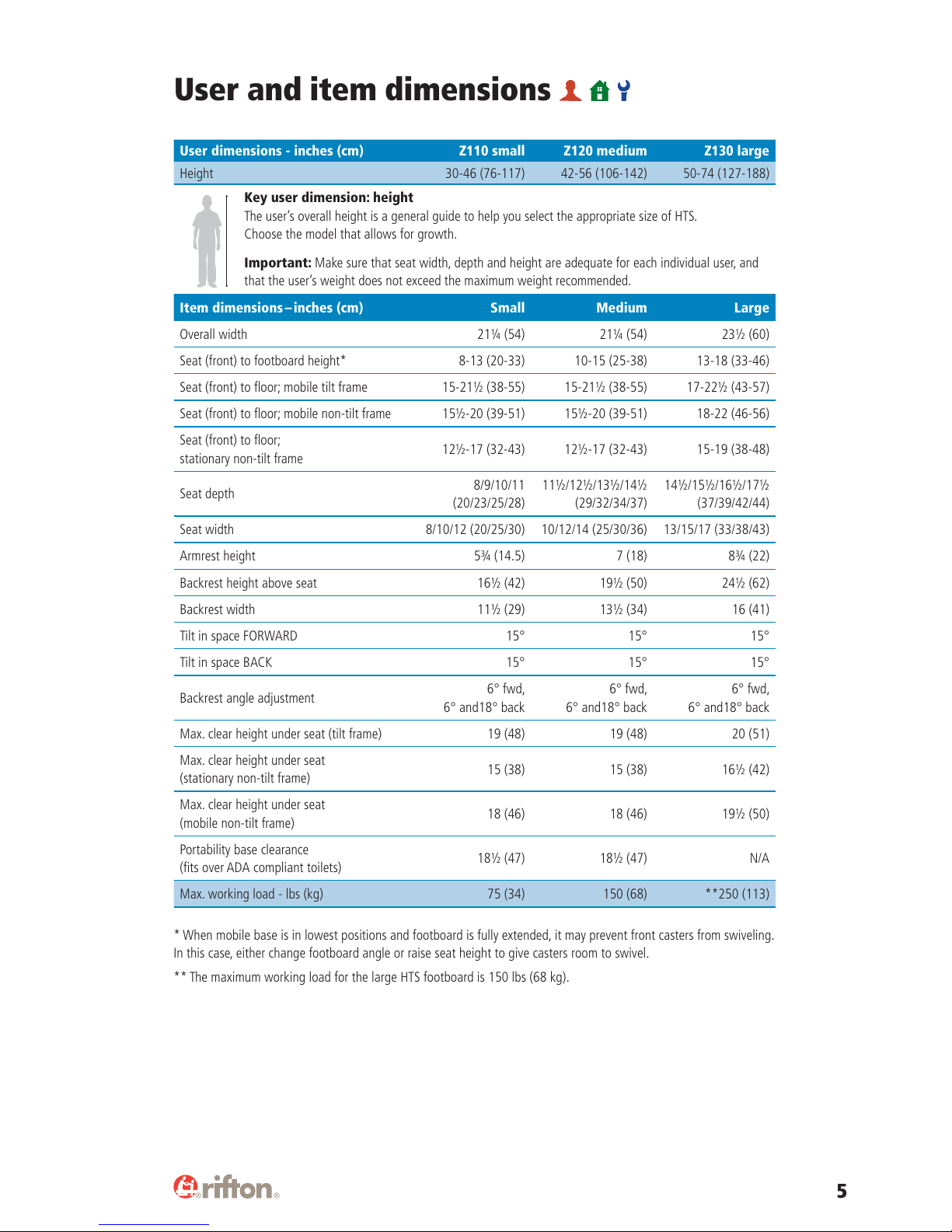
Key user dimension: height
The user’s overall height is a general guide to help you select the appropriate size of HTS.
Choose the model that allows for growth.
Important: Make sure that seat width, depth and height are adequate for each individual user, and
that the user’s weight does not exceed the maximum weight recommended.
Item dimensions – inches (cm) Small Medium Large
Overall width 21¼ (54) 21¼ (54) 23½ (60)
Seat (front) to footboard height* 8-13 (20-33) 10-15 (25-38) 13-18 (33-46)
Seat (front) to floor; mobile tilt frame 15-21½ (38-55) 15-21½ (38-55) 17-22½ (43-57)
Seat (front) to floor; mobile non-tilt frame 15½-20 (39-51) 15½-20 (39-51) 18-22 (46-56)
Seat (front) to floor;
stationary non-tilt frame 12½-17 (32-43) 12½-17 (32-43) 15-19 (38-48)
Seat depth 8/9/10/11
(20/23/25/28)
11½/12½/13½/14½
(29/32/34/37)
14½/15½/16½/17½
(37/39/42/44)
Seat width 8/10/12 (20/25/30) 10/12/14 (25/30/36) 13/15/17 (33/38/43)
Armrest height 5¾ (14.5) 7 (18) 8¾ (22)
Backrest height above seat 16½ (42) 19½ (50) 24½ (62)
Backrest width 11½ (29) 13½ (34) 16 (41)
Tilt in space FORWARD 15° 15° 15°
Tilt in space BACK 15° 15° 15°
Backrest angle adjustment 6° fwd,
6° and18° back
6° fwd,
6° and18° back
6° fwd,
6° and18° back
Max. clear height under seat (tilt frame) 19 (48) 19 (48) 20 (51)
Max. clear height under seat
(stationary non-tilt frame) 15 (38) 15 (38) 16½ (42)
Max. clear height under seat
(mobile non-tilt frame) 18 (46) 18 (46) 19½ (50)
Portability base clearance
(fits over ADA compliant toilets) 18½ (47) 18½ (47) N/A
Max. working load - lbs (kg) 75 (34) 150 (68) **250 (113)
* When mobile base is in lowest positions and footboard is fully extended, it may prevent front casters from swiveling.
In this case, either change footboard angle or raise seat height to give casters room to swivel.
** The maximum working load for the large HTS footboard is 150 lbs (68 kg).

6
Check your order
Your Rifton HTS has been shipped according to your specifications. It will require some
tool-free assembly. Follow these instructions to ensure that your product is assembled
and used correctly. This product manual is comprehensive, and may discuss features not
included in your configuration of the HTS.
Basic components
A Quick Reference Guide for the HTS can be dowloaded from a QR code on
the back of the backrest.
Seat depth
The side pieces allow for seat depth
adjustment. Lift the blue latches on both
outer sides (see figure 6a), move both sides
together to the desired seat depth and find
a latched position.
This same adjustment will also enable both
sides to slide off the seat towards the front
for cleaning the area underneath.
Backrest angle
The backrest angle can be adjusted 6°
forward, 6° back, and 18° back (see figure
6b). Raise both back angle triggers, adjust
to desired angle and release into a latched
position (see figure 6c).
Figure 6a
Seat depth latch
Figure 6c
Back angle trigger
Figure 6b
-18°+6° -6°Backrest
removal
Tip: Every blue lever or button
indicates a point of adjustment.

7
Seatbelt
To prevent falls,
strangulation, head
entrapment or other injuries, always use
seatbelt when the tray, chest strap or
headrest are in use.
Every HTS is provided with a seatbelt.
To attach the seatbelt insert the seatbelt
attachment clip (see figure 7b) into the
socket at the back end of the side piece.
Check to ensure that the seatbelt latches
into place.
For users that tend to slide forward on
the seat, you may benefit from threading
the seat belt to the inside of the backrest
supports (see figure 7c).
On the small HTS there is an additional
option for seat belt threading to ensure a
more secure positioning for small active
users. Thread the seat belt through the
hooks provided at the bottom back edge of
the seat (see figure 7d).
Backrest installation
or removal
To install the backrest: Tip the backrest
toward the front (see figure 7a). Insert the
bottom end of the backrest between the
latch plates while raising the backrest angle
triggers. Firmly press down on the backrest
while rotating it back towards the first
latched position.
To remove the backrest, adjust the back
angle all the way forward. Then lift the
backrest up.
Figure 7b
Figure 7a
Angle triggers
Latch
plates
Clip
Figure 7c
Figure 7d
WARNING

8
To prevent falls and
injuries, always make
sure both seat hooks are inserted into the
base sockets and that both seat latches
are latched to base.
Attaching the seat
Insert both hooks at the rear of the seat
into the sockets of the frame (see figure
8a). Then push front of seat down onto
frame until the latches audibly engage.
Removing the seat
To remove the seat from a base, pull both
seat latches under the front edge of the
seat (see figure 8b) and lift it from the
base.
Bases
Figure 8a
Hooks into
socket
Figure 8b
Seat latches
A
Figure 7c
Armrests
To attach the armrest, insert the bottom of
the armrest into the oval slots in the side
pieces and press down firmly until it latches
into place (see figure 7c).
To remove the armrest, squeeze the release
button (A) and pull the armrest up.
WARNING
Tip: Armrests of different sizes can
be retrofitted.

9
Figure 9b
Figure 9c
Tilt trigger
Figure 9d
Brake lever
Height
latches
Figure 9a
Base height adjustment
To prevent falls and
injury, do not adjust
height with user in the product.
To lower the seat, squeeze both height
latches on the frame uprights (see figure
9a) while supporting the weight of the
seat. Lower both sides evenly to prevent
binding.
To raise the seat, flip up the footboard, put
one foot on the frame cross bar, and pull
up on the seat frame (there is no need to
release the height latches).
Tilt-in-space adjustment
The tilt-in-space adjustment is available
on the Z122 and Z132 bases. Use the tilt
trigger at the right rear of the seat (see
figure 9b) to release the two locking gas
springs. Tilt adjusts 15° forward and 15°
back. It is easy to tilt the HTS with the user
in the product.
Casters and stationary feet
The casters and stationary rubber feet can
easily be replaced or exchanged. Simply
pull the caster stem or rubber foot out of
the end cap (see figure 9c). Ensure that
replacement casters or feet are inserted to
their full depth.
Caster brakes
To apply the brake, step down on the brake
lever. To release the brake, raise the lever
(see figure 9d).
WARNING
Tip: If adjustment feels tight, then
try with the tilt-in-space all the way
forward or back.

10
Footboard
To prevent falls,
tipping or other injury:
• Do not exceed 150 pounds on
the footboard.
• Do not stand on footboard while it is
angled forward.
• Do not place maximum load at front
edge of footboard.
The footboard is included with
mobile bases.
Height adjustment
To adjust footboard height, press both
height buttons, moving the footboard to
the desired height, then release the buttons
at a latched position (see figure 10a).
Footboard angle adjustment
The angle of the footboard can be adjusted
by pushing up on both angle triggers while
moving the footboard to the desired angle
(see figure 10b).
Footboard can be folded up out of the way
for floor-level transfers (see figure 10c).
Figure 10a
Figure 10b
Figure 10c
Height
buttons
Angle
triggers
CAUTION

11
Mounting bars
To prevent falls or
injuries, ensure that
the toilet is securely attached to the
floor and that the seat bolts are in good
condition before attaching the mounting
bar. Inspect the toilet stability and seat
bolts at regular intervals while the
mounting bar is in use.
There are two kinds of mounting bars, to fit
either standard round, or elongated toilets
(see figure 11a).
The mounting bar attaches with the bolts
that hold the seat, and provides a firm
attachment point for the seat and back
units (see figure 11b).
To determine which type of mounting bar
you need, measure from the centerline
of the seat bolts to the front edge of the
porcelain bowl. Use a standard toilet
mounting bar if this is 17”(43 cm) or
less, otherwise use the elongated toilet
mounting bar.
Attachment of seat to
mounting bar
To prevent falls or
injuries, ensure that
both hooks are fully engaged in the
sockets of the mounting bar before using
the HTS.
To attach the seat to the mounting bar,
move the backrest out of the way by tilting
or sliding it forward, then insert both
hooks on the seat into the sockets on the
mounting bar and lower the seat onto the
toilet bowl (see figure 11c).
Figure 11a
Figure 11b
Figure 11c
Elongated
Standard
Hooks
WARNING
WARNING

12
Accessories
Seat and back pads
The seat and back pads are removable for
cleaning. They are made of Polyurethane with a
durable integral skin.
There are two styles of seat pad. One has
a wider opening which opens to the rear
facilitating hygiene care (see figure 12a). The
second one has a narrower opening, which is
closed at the back and provides more support
for the user (see figure 12b).
The seat and back pads attach with four snaps
that snap into the holes in the seat and backrest
(see figure 12c).
Headrest
To prevent head
entrapment or injury,
always use seatbelt while the headrest
is in use.
To attach and adjust headrest height,
push height button (A). Insert the stem of
headrest into the headrest slot (see figure
12d) to desired height. Release the button
and adjust height until the latch audibly
engages.
To adjust depth and angle of headrest,
loosen oval knobs (B), adjust to the desired
position and retighten the knobs.
Figure 12a
Figure 12c
Figure 12d
Figure 12b
A
B
SnapHole
WARNING

13
Figure 13a
Figure 13b
Figure 13c
A
B
Butterfly harness
To prevent falls,
strangulation or
other injuries:
• Tighten the seatbelt portion of the
butterfly harness before tightening the
upper straps.
• Check fit of harness after every
adjustment.
To attach the butterfly harness, remove the
center section of the seatbelt (A). Replace it
with the butterfly harness (B), which has a
built-in seatbelt (see figure 13a).
Adjust the seatbelt tension, then clip the
shoulder straps to the sockets on the
backrest (see figure 13b).
For small users, you may wish to attach the
shoulder straps through the upper slot in
the backrest (see figure 13c).
WARNING

14
Anterior support/tray
To prevent falls,
strangulation or other
injuries, always use a seatbelt when the
tray is in use.
The anterior support has a padded surface
for the user to lean against, which provides
an excellent, forward-leaning, toileting
position with trunk and arms supported by
the tray (see figure 14a).
To adjust tray depth, squeeze latch under
the front of tray (see figure 14b).
Figure 14a
Figure 14b
Latch
WARNING

15
Lateral supports
Lateral supports are available with or
without a chest strap for secure upper
trunk positioning. They may be adjusted
separately, in height, angle and width using
the knob (B) behind the backrest.
To attach and/or adjust lateral support
(A), loosen knob (B) and insert the key
(C) into extrusion (D) at the rear of the
backrest. Adjust height, angle and width
of lateral support to fit client by sliding it
up and down, sliding bracket (E) along its
slot and by rotating bracket (E) around the
knob. When desired adjustment is reached,
tighten knob firmly (see Figure 15a).
Chest strap
To prevent falls,
strangulation or
other injuries:
• Always use seatbelt when the chest
strap is in use.
• Always ensure that chest strap is
correctly adjusted.
The chest strap threads onto the lateral
supports as shown (see figure 15b). The
chest strap should thread to the inside of
the lateral supports (see figure 15c).
Figure 15a
Figure 15c
A
D
C
BE
Figure 15b
WARNING

16
Hip guides
The seat width may be adjusted with a pair
of hip guides that attach onto the armrests.
In the first position they reduce the seat
width by 2” (5 cm), and in the second
position they reduce it by 4”(10 cm) (see
figure 16a).
Slide the hip guide onto the armrest with
the notch in the hip guide up and back.
Insert the armrest into the armrest slot
through the hip guide.
Pan
The pan (see figure 16b) enables the HTS to
be used as a stand-alone commode. Insert
the pan into the tracks under the seat, from
the back of the chair. Push until it latches
into place. Remove it by pulling straight
back (see figure 16c).
Bowl adapter
The bowl adapter (see figure 16d)
accommodates situations where the hole
in the HTS isn’t fully over the hole in the
toilet. It is inserted at the front edge of the
hole, under the seat pad. A seat pad must
be used in conjunction with the
bowl adapter.
Figure 16a
Figure 16b
Figure 16c
Notch at back
Figure 16d

17
Deflectors
The standard deflector inserts into the
slot on the seat pad with the hollow cup of
the deflector toward the user
(see figure 17a).
The splash guard provides even more
coverage. It is held against the user with
the seatbelt or butterfly harness (see figure
17b).
Abductor
The padded abductor inserts into the slot
at the front edge of the seat. It can be
removed by squeezing the blue latch (A)
and pulling the abductor out (see figure
17c).
To minimize risk of
infectious disease
transmission, the HTS should be cleaned
and disinfected between uses by
different patients. Inadequate cleaning
and disinfecting of equipment may
increase the risk of cross contamination.
Remove the Polyurethane pads for cleaning
with soapy water or a mild disinfectant.
Figure 17a standard deflector
Figure 17b splash guard
Figure 17c
A
Ribs in seat pad
Tip: Adding the abductor to the
standard deflector provides stability to
the deflector (see figure 17c).
CAUTION

18
Calfrest
This option requires the use of
a footboard.
The calfrest attaches above the footboard
(see figure 18a). It should be removed if the
footboard is in the top positions.
The calfrest attaches to the footboard
uprights. With the webbing at the back,
and rounded corners down, loop the
webbing around the uprights and thread
webbing through the metal ring at the
front, engaging the hook and loop snugly
around uprights (see figure 18b).
Ankle straps
This option requires the use of
a footboard.
To attach the ankle straps:
1. Insert the webbing tab into the
horizontal slot at the back of the
footboard, (see figure 18c).
2. Turn the webbing to slide it into the
vertical slot and pull to engage it (see
figure 18d).
3. Adjust the straps to fit the user’s needs.
The straps with hook
and loop closures may be
laundered at 160F (70C) or less. Engage
the closures before washing. Do not iron.
Figure 18a
Figure 18b
Figure 18c
Figure 18d
NOTICE

19
Footboard for mounting
bar attachment
To prevent falls or
other injury:
• Ensure that the square metal tubing
attaching the footboard to the seat
rests on the front edge of the toilet.
• Do not stand on footboard for
mounting bar attachment.
To attach a footboard to the HTS when
used on the toilet with a mounting bar (see
figure 19a):
1. Turn the HTS seat upside down (see
figure 19b).
2. Insert the small metal tabs at the end of
metal tubing on footboard (A), into slots
at the back of the seat.
3. Push footboard down firmly to latch
square tubing onto blue latches (B).
4. Attach HTS to mounting bar
(see page 11).
The other adjustments for the footboard
are the same as described on page 10.
Tub base
To prevent falls and
injuries, always make
sure both seat hooks are inserted into the
base sockets and that both seat latches
are latched to base.
The tub base is for use in a bathtub to
bathe or shower the client (see figure 19c).
Attaching the seat
Insert both hooks at the rear of the seat
into the sockets of the tub base frame
(see figure 19d). Then push front of seat
down onto frame until the latches audibly
engage.
Figure 19a
Figure 19b
Figure 19c
Figure 19d
Hooks into
socket
A
B
WARNING
WARNING

20
Portability base with
carry-bag
To prevent falls and
injuries:
• The portable base is intended for
travel use only and should not be used
as the primary base. Ensure adequate
stability when using the portable base.
• Check that the two pieces of the frame
are fully engaged before attaching the
seat.
• Always make sure both seat hooks
are inserted into the base sockets and
that both seat latches at the front are
latched to base.
The portability base is a light-weight,
foldable frame with a carry-bag (see figure
20a). This base fits in the back pouch of
the carry-bag.
The seat, back, armrests and other
accessories can go into the front pouch of
the carry-bag (see figure 20b).
To assemble the base, unfold both halves
of the frame, insert the square peg of
one half into the square tube of the other
half of the frame (see figure 20c). Make
sure the two pieces of the frame are fully
engaged before attaching the seat.
Then attach the seat to the frame (see
figure 20d) as described on previous page
(see figure 19d).
Figure 20a
Figure 20c
Figure 20d
Figure 20b
WARNING
Other manuals for Z110
1
This manual suits for next models
2
Table of contents
Other Rifton Medical Equipment manuals
Popular Medical Equipment manuals by other brands

Fresenius Kabi
Fresenius Kabi OPTIMA PT-VS-S Technical manual

Sentier
Sentier Vetcorder Pro user manual

Whitehall
Whitehall Thermalator LITTLE Therm Instructions for operation and care

Beurer
Beurer MG 206 HD-enjoy Instructions for use

Stryker
Stryker SurgiLav Plus Instructions for use

Stryker
Stryker FL26E Maintenance manual