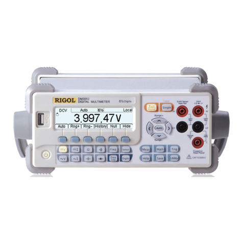
Rigol DM3000 Series User manual

Service Guide RIGOL
Publication number: SGC01108-1210
Dec. 2008
DM3000 Series Digital Multimeter
DM3061/2/4
DM3051/2/4
© 2008 RIGOL Technologies, Inc. All Rights Reserved


RIGOL
Service Guide for DM3000 Series
I
Copyright Information
© 2008 RIGOL Technologies, Inc. All Rights Reserved.
RIGOL products are protected by patent law in and outside of P.R. China.
Information in this publication replaces all previously corresponding material.
RIGOL Technologies, Inc. reserves the right to modify or change part of or all the
specifications and pricing policies at company’s sole decision.
NOTE: RIGOL is registered trademark of RIGOL TECHNOLOGIES, INC.

RIGOL
Service Guide for DM3000 Series
II
Safety Notices
Review the following safety precautions carefully before operating the instrument to
avoid any personal injuries or damages to the instrument and any products connected
to it.
To avoid potential hazards, it is necessary to use the instrument as specified by this
user’s guide only.
The instrument should be serviced by qualified personnel only.
Avoid Fire or Personal Injury.
Use Proper Power Cord. Use the power cord designed for the instrument as
authorized in your country only.
Connect and Disconnect Correctly. Do not connect or disconnect test leads while
they are connected to a voltage source.
Ground The Instrument. The instrument is grounded through the grounding
conductor of the power cord. To avoid electric shock the instrument grounding
conductor(s) must be grounded properly before making connections to the input or
output terminals of the instrument.
Observe All Terminal Ratings. To avoid fire or shock hazard, observe all ratings
and marks on the instrument. Follow the user’s guide for further ratings information
before making connections to the instrument.
Do Not Operate Without Covers. Do not operate the instrument with covers or
panels removed.
Use Proper Fuse. Use the fuse of the type, voltage and current ratings as specified
for the instrument.
Avoid Circuit or Wire Exposure. Do not touch exposed connections and
components when power is on.
Do Not Operate With Suspected Failures. If you suspect there is damage with
this product, you have it inspected by qualified service personnel authorized by
RIGOL before further operations.
Provide proper ventilation.

RIGOL
Service Guide for DM3000 Series
III
Do Not Operate in Wet/Damp Conditions.
Do Not Operate in an Explosive atmosphere.
Keep Product Surfaces Clean and Dry.
The disturbance test of all the models meet the limit values of A in the
standard of EN 61326: 1997+A1+A2+A3, but can’t meet the limit values of
B.
WARNING
IEC Measurement Category II. The HI and LO input terminals may be connected to
mains in IEC Category II installations for line voltages up to 300 VAC. To avoid the
danger of electric shock, do not connect the inputs to mains for line voltages above
300 VAC.
Protection Limits: To avoid instrument damage and the risk of electric shock, do not
exceed any of the Protection Limits defined in the following section.
IEC Measurement Category II Overvoltage Protection
To protect against the danger of electric shock, the RIGOL DM3000 series Digital
Multimeter provides overvoltage protection for line-voltage mains connections
meeting both of the following conditions: the HI and LO input terminals are connected
to the mains under Measurement Category II conditions, defined below, and The
mains are limited to a maximum line voltage of 300 VAC. IEC Measurement Category
II includes electrical devices connected to mains at an outlet on a branch circuit.
Such devices include most small appliances, test equipment, and other devices that
plug into a branch outlet or socket. The DM3000 series Digital Multimeter may be used
to make measurements with the HI and LO inputs connected to mains in such devices,
or to the branch outlet itself (up to 300 VAC). However, the DM3000 series Digital
Multimeter may not be used with its HI and LO inputs connected to mains in
permanently installed electrical devices such as the main circuit-breaker panel,
sub-panel disconnect boxes, or permanently wired motors. Such devices and circuits
are subject to overvoltage that may exceed the protection limits of the DM3000 series
Digital Multimeter.
NOTE: Voltages above 300 VAC may be measured only in circuits that are isolated
from mains. However, transient overvoltage is also present on circuits that are
isolated from mains. The DM3000 series Digital Multimeter is designed to safely

RIGOL
Service Guide for DM3000 Series
IV
withstand occasional transient overvoltage up to 2500 Vpk. Do not use this equipment
to measure circuits where transient overvoltage could exceed this level.

RIGOL
Service Guide for DM3000 Series
V
Safety Terms and Symbols
Terms in This Guide. These terms may appear in this guide:
WARNING: Warning statements identify conditions or practices that could
result in injury or loss of life.
CAUTION: Caution statements identify conditions or practices that could
result in damage to this product or other property.
CAT II (300V): IEC Measurement Category II. Inputs may be connected to
mains (up to 300 VAC) under Category II Overvoltage
conditions.
Terms on the Product: These terms may appear on the product:
DANGER indicates an injury hazard may happen immediately.
WARNING indicates an injury hazard may not happen immediately.
CAUTION indicates that a potential damage to the instrument or other property
may occur.
Symbols on the Product: These symbols may appear on the Instrument:
!
!
!
Hazardous
Voltage
Refer to
Instructions
Protective
Earth
Terminal
Earth
Ground
Chassis
Ground
!

RIGOL
Service Guide for DM3000 Series
VI
General-Purpose Multimeter
The document covers the description and introduction of six models of DM3000 Series
Digital Multimeter:
DM3061, DM3062, DM3064;
DM3051, DM3052, DM3054.
DM3000 Series Digital Multimeter naming rules:
Prefix of desktop Digital Multimeter
Serial Number
6-6½ , 5-5¾ digit
No.
1-Basic; 2-LAN/GPIB interface;
4-Multiplexer plate with the model and LAN/GPIB interface.
Application examples:
DM3061-6½ DM3000 series, Basic type.
DM3062-6½ DM3000 series, Basic type, equipped with LAN/GPIB module.
DM3064-6½ DM3000 series, Basic type, equipped with LAN/GPIB and multiplexer
module.
DM3051-5¾ DM3000 series, Basic type.
DM3052-5¾ DM3000 series, Basic type, equipped with LAN/GPIB module.
DM3054-5¾ DM3000 series, Basic type, equipped with LAN/GPIB and multiplexer
module.
30
6
1
DM

RIGOL
Service Guide for DM3000 Series
VII
RIGOL DM3000 Series Digital Multimeter is equipment designed for high-precision,
multifunction, automation measurements. The series includes 6½ digits multimeter,
with high-speed data acquisition, automatic measurements, multiplexer, mathematical
operations, and flexible user sensor configurations etc.
DM3000 has a high-resolution monochrome LCD display system for simple waveform
display and record. The concise and user-friendly layout of the front panel has a
keyboard, and back lighted functional buttons, embedded with operating instructions
makes the instrument more flexible, and capable. Interface includes RS-232, USB,
LAN, and GPIB for disk storage and print. It supports virtual terminal display and
control, and remote network access.
With the performance and characteristics given below, you will understand how
DM3000 can satisfy your measurement requirements.
Resolving Resolution: > 6½ digits and 2,400,000 Count;
50kSa/s data sampling rate can be used, such as the rapidly changing
high-precision audio waveform data. Meanwhile waveform can be displayed on
LCD Screen;
24 measurement functions
DC voltage and current, AC voltage and current, two-wire and four-wire
resistance, capacitance, continuity test, diode test, frequency, cycle, ratio
measurements, sensor measurement, and so on;
Math include: maximum, minimum, limit, average, dBm, dB;
Data acquisition functions include: data records, inspection, and automatic
measurement;
True RMS AC voltage and current measurement;
16-Channels multiplexer functional measurement and control software (optional);
DC voltage >10GΩ input impedance to achieve the range of 48V (± 24V);
10 groups measuring set-up storage and unlimited setup through PC interface;
256 x 64 pixel monochrome LCD;
I/O: RS-232, USB, LAN and GPIB;
Built-in USB Host to support USB disk and USB printer;
Simple, convenient and flexible control software: Ultralogger and Ultrasensor.

RIGOL
Service Guide for DM3000 Series
VIII
Structure of This Document
Chapter 1 Performance Specifications
List the Performance specifications of DM3000 series.
Chapter 2 Quick Start
Help users to be familiar with the operating skills of DM3000.
Chapter 3 Performance Test
Introduce how to test the performance so as to know about its current state of
DM3000 well.
Chapter 4 Calibration
Guide you how to calibrate DM3000.
Chapter 5 Disassembly and assembly
Introduce how to disassemble and assemble DM3000 in order to know about more
details about its structure.
Chapter 6 Troubleshooting and General Care
Provide the methods of troubleshooting and general care.
Chapter 7 Service and Support
Information about Service and Support and the like.

RIGOL
Service Guide for DM3000 Series
IX
Contents
General-Purpose Multimeter ......................................................................... VI
Chapter 1 Performance & Specifications ..............................................1-1
Mechanical Specifications............................................................................1-2
Technical Specifications ..............................................................................1-3
Specifications of DM306x .....................................................................1-3
Specifications of DM305x ................................................................... 1-13
Chapter 2 Quick Start ...........................................................................2-1
General Inspection .....................................................................................2-2
Inspect the Instrument ........................................................................2-2
Check the List of Accessories ................................................................2-2
Handle Adjustment.....................................................................................2-3
Introduction of Front Panel .........................................................................2-4
Introduction of Rear Panel ..........................................................................2-5
Introduction of User Interface .....................................................................2-5
Chapter 3 Performance Test .................................................................3-1
Equipments for Test ...................................................................................3-2
Performance Test .......................................................................................3-3
Quick Test ...........................................................................................3-3
Common Test ......................................................................................3-3
Optional AC Voltage Test .................................................................... 3-14
Optional AC Current Test .................................................................... 3-15
Capacitance Test................................................................................ 3-16
Software Connection Test ......................................................................... 3-17
Chapter 4 Calibration............................................................................4-1
Calibration Security Code ............................................................................4-2
Calibration Notice .......................................................................................4-3
DC Voltage, DC Current, Resistance Calibration ............................................4-4
AC Voltage and AC Current Calibration.........................................................4-6
Frequency Calibration .................................................................................4-8
Capacitance Calibration...............................................................................4-8
Chapter 5 Disassembly & Assembly...................................................... 5-1
The Disassembly and Assembly Notice.........................................................5-2
The 3D View of DM3000 .............................................................................5-3

RIGOL
Service Guide for DM3000 Series
X
To Disassemble and Assemble .................................................................... 5-5
Handle, Rear Panel and Metallic Shell .......................................................... 5-5
To Disassemble and Assemble .................................................................... 5-8
Fuse Socket, BNC Module and GPIB PCB ..................................................... 5-8
To Disassemble and Assemble ...................................................................5-11
Filter Board and Transformer .....................................................................5-11
To Disassemble and Assemble ...................................................................5-12
Front Panel and LCD .................................................................................5-12
To Disassemble and Assemble ...................................................................5-13
Multiplexer Board, Motherboard and Key Board PCB ....................................5-13
Chapter 6 Troubleshooting & Maintenance...........................................6-1
DM3000 Principle Introduction .................................................................... 6-2
Troubleshooting......................................................................................... 6-4
Common Troubleshooting .................................................................... 6-4
Components Inspection ....................................................................... 6-7
Replaceable Part List ..........................................................................6-10
Maintenance and Cleaning.........................................................................6-12
Chapter 7 Service & Support .................................................................7-1
Warranty................................................................................................... 7-1
Contact Us ................................................................................................ 7-3
Index ................................................................................................................ 1

RIGOL
Service Guide for DM3000 Series
XI
Figure Contents
Figure 1-1 Dimension of DM3000................................................................1-2
Figure 2-1 The Method of Adjusting Handle.................................................2-3
Figure 2-2 Adjustable Positions for Handle...................................................2-3
Figure 2-3 Sketch map of Front Panel .........................................................2-4
Figure 2-4 Sketch map of Rear Panel ..........................................................2-5
Figure 2-5 Sketch map of User Interface .....................................................2-5
Figure 3-1.................................................................................................3-4
Figure 3-2 UltraLogger is successfully connected ....................................... 3-17
Figure 3-3 UltraSensor is successfully connected........................................ 3-18
Figure 4-1 The Input HI-LO and Sense/Ref HI-LO Terminals in Short Circuit...4-4
Figure 5-1 The Exterior 3D View of DM3000 ................................................5-3
Figure 5-2 The Interior 3D View of DM3000 ................................................5-4
Figure 5-3 The Schematic of Disassembling and Assembling Handle..............5-5
Figure 5-4 The Schematic of Disassembling and Assembling Rear Panel ........5-6
Figure 5-5 The Schematic of Disassembling and Assembling Metallic Shell .....5-7
Figure 5-6 The Schematic of Disassembling and Assembling Fuse Socket ......5-8
Figure 5-7 The Schematic of Disassembling and Assembling BNC Module....5-9
Figure 5-8 The Schematic of Disassembling and Assembling GPIB PCB...... 5-10
Figure 5-9 The Schematic of Disassembling and Assembling....................... 5-11
Figure 5-10 The Schematic of Disassembling and Assembling ..................... 5-12
Figure 5-11 The Schematic of Disassembling and Assembling Multiplexer Board
....................................................................................................... 5-13
Figure 5-12 The Schematic of Disassembling and Assembling Motherborad . 5-14
Figure 5-13 The Schematic of Disassembling and Assembling Key Board PCB
....................................................................................................... 5-15
Figure 6-1 Circuit Diagram of DM3000 series ...............................................6-2
Figure 6-2 The Sketch Map of Fuse Replacement.........................................6-4
Figure 6-3 Transformer Sketch Map ............................................................6-7

RIGOL
Service Guide for DM3000 Series
XII
Table Contents
Table 3-1 Recommended Equipments ......................................................... 3-2
Table 3-2 Zero Offset of the Standard Equipment (DM306X) ........................ 3-5
Table 3-3 Zero Offset of the Standard Equipment (DM305X) ........................ 3-6
Table 3-4 DC Gain Error of the Standard Equipment (DM306X)..................... 3-7
Table 3-5 DC Gain Error of the Standard Equipment (DM305X)..................... 3-8
Table 3-6 AC Voltage Gain Error of the standard equipment (DM306X).......... 3-9
Table 3-7 AC Voltage Gain Error of the Standard Equipment (DM305X) ....... 3-10
Table 3-8 AC Current Gain Error of the Standard Equipment (DM306X) ....... 3-11
Table 3-9 AC Current Gain Error of the Standard Equipment (DM305X) ....... 3-12
Table 3-10 Frequency Gain Error of the Standard Equipment (DM306X) ...... 3-13
Table 3-11 Frequency Gain Error of the Standard Equipment (DM305X) ...... 3-13
Table 3-12 Accessional AC Voltage Test Error (DM306x)............................. 3-14
Table 3-13 Accessional AC Voltage Test Error(DM305X).......................... 3-14
Table 3-14 Accessional AC Current Test Error(DM306X)......................... 3-15
Table 3-15 Accessional AC Current Test Error(DM305X)......................... 3-15
Table 3-16 Capacitance Test Error of the Standard Equipment (DM306X) .... 3-16
Table 3-17 Capacitance Test Error of the Standard Equipment (DM305X) .... 3-16
Table 4-1 DC Zero and DC Gain Calibration Input Value (DM306X)................ 4-5
Table 4-2 DC Zero and DC Gain Calibration Input Value (DM305X)................ 4-5
Table 4-3 AC Calibration Input Value .......................................................... 4-7
Table 4-4 Capacitance Calibration input Value ............................................. 4-8
Table 6-1 Check Table of Voltages among Windings of Transformer .............. 6-8
Table 6-2 Replaceable Part List ................................................................ 6-11

RIGOL
Service Guide for DM3000 Series
1-2
Mechanical Specifications
Weight: 2.5 kg
Dimension: W× H× D=231.6mm× 107mm× 290.5mm
Figure 1-1 Dimension of DM3000

RIGOL
Service Guide for DM3000 Series
1-3
Technical Specifications
Specifications of DM306x
DC Characteristics
Accuracy Specifications (% of reading + % of range) [1]
Function
Range[3]
Test Current
or Burden
Voltage
24 Hour[2]
Tcal± 1℃
90 Day
Tcal± 5℃
1 Year
Tcal± 5℃
Temperature
Coefficient
0 ℃to
(Tcal–5 ℃)
(Tcal + 5 ℃) to
55 ℃
DC
Voltage
200.0000mV
0.0030+0.00
30
0.0065+0.00
65
0.0085+0.00
70
0.0005+0.0007
2.000000V
0.0020+0.00
06
0.0060+0.00
07
0.0078+0.00
07
0.0005+0.0001
20.00000V
0.0020+0.00
04
0.0065+0.00
05
0.0085+0.00
05
0.0005+0.0001
200.0000V
0.0020+0.00
06
0.0082+0.00
11
0.0100+0.00
12
0.0007+0.0002
1000.000V[5]
0.0025+0.00
06
0.0095+0.00
10
0.0110+0.00
10
0.0010+0.0001
DC
Current
2.000000mA
<0.03V
0.010+0.014
0.060+0.035
0.076+0.050
0.0027+0.0070
20.00000mA
<0.3V
0.010+0.002
0.058+0.006
0.075+0.006
0.0027+0.0007
200.0000mA
<0.3V
0.020+0.002
0.065+0.005
0.081+0.005
0.0027+0.0008
1.000000A
<0.3V
0.020+0.016
0.065+0.030
0.073+0.030
0.0027+0.0062
10.00000A [7]
<0.6V
0.300+0.020
0.330+0.020
0.330+0.020
0.0030+0.0025
Resistance[4
]
200.0000Ω
1mA
0.0106+0.00
97
0.018+0.011
0.020+0.011
0.0008+0.0007
2.000000kΩ
1mA
0.0022+0.00
11
0.010+0.002
0.015+0.002
0.0008+0.0001
20.00000kΩ
100uA
0.0020+0.00
06
0.010+0.001
0.015+0.001
0.0008+0.0001
200.0000kΩ
10uA
0.0020+0.00
05
0.010+0.001
0.015+0.001
0.0008+0.0001
1.000000MΩ
2uA
0.0020+0.00
10
0.010+0.001
0.015+0.001
0.0008+0.0002
10.00000MΩ
200nA
0.0112+0.00
5
0.0550+0.00
6
0.056+0.006
0.0060+0.0004
100.0000MΩ
200nA||10M
Ω
0.300+0.010
0.800+0.011
0.800+0.015
0.1500+0.0002
Diode Test
2.4000V [6]
1mA
0.005+0.050
0.008+0.050
0.010+0.050
0.0010+0.0020
Continuity
2000Ω
1mA
0.005+0.050
0.008+0.050
0.010+0.050
0.0010+0.0020
Notes:
[1] Specifications are for 60 minute warm–up and set reading resolution as 6½ .
[2] Relative to calibration standards.

RIGOL
Service Guide for DM3000 Series
1-4
[3] 20% over range on all ranges, except DCV 1000V, ACV 750V, DCI and ACI 10A range.
[4] Specifications are for 4–wire resistance function, or 2–wire resistance using Math Null. Without
Math Null, add 0.2 Ω additional errors in 2–wire resistance function.
[5] For each additional volt over ± 500 VDC add 0.02 mV of error.
[6] Accuracy specifications are for the voltage measured at the input terminals only. 1mA test
current is typical. Variation in the current source will create some variation in the voltage drop
across a diode junction.
[7] As continuous current higher than 7A DC or AC RMS, 30 seconds needs to be off after connecting
30s.
Settling Considerations:
Setting time of readings is affected by source impedance, cable dielectric characteristics and input
signal changes. Generally, the Settling time of Common readings is about 1.5s when Low source
impedance less than 1kΩ.

RIGOL
Service Guide for DM3000 Series
1-5
AC Characteristics
Accuracy Specifications (% of reading + % of range) [1]
Function
Range[3]
Frequency
Range
24 Hour[2]
Tcal± 1℃
90 Day
Tcal± 5℃
1 Year
Tcal± 5℃
Temperature
Coefficient
0℃to (Tcal–5 ℃)
(Tcal + 5 ℃) to 55 ℃
True
RMS AC
Voltage
[4]
200.000m
V
3Hz-10Hz
5.0+0.05
5.0+0.07
5.1+0.07
0.15+0.006
10Hz-40Hz
0.53+0.05
0.57+0.06
0.60+0.07
0.035+0.004
40Hz-20kHz
0.08++0.05
0.14+0.06
0.15+0.07
0.005+0.004
20kHz-50kHz
0.10+0.05
0.14+0.06
0.16+0.05
0.011+0.005
50kHz-100kHz
0.5+0.10
0.6+0.10
0.60+0.10
0.06+0.008
100kHz-300kHz
4.0+0.80
4.5+0.80
4.50+0.80
0.2+0.02
2.00000V
to
750.00V
3Hz-10Hz
5.0+0.05
5.0+0.07
5.10+0.07
0.15+0.006
10Hz-40Hz
0.35+0.05
0.37+0.06
0.38+0.07
0.035+0.003
40Hz-20kHz
0.08+0.05
0.10+0.06
0.11+0.07
0.005+0.003
20kHz-50kHz
0.40+0.05
0.40+0.06
0.40+0.07
0.011+0.005
50kHz-100kHz
0.55+0.10
0.60+0.10
0.60+0.10
0.07+0.008
100kHz-300kHz
4.0+0.80
4.0+0.80
4.00+0.80
0.2+0.02
True
RMS AC
Current[
5]
20.0000m
A
3Hz-10Hz
5.0+0.05
5.1+0.07
5.1+0.07
0.15+0.006
10Hz-40Hz
0.55+0.05
0.61+0.06
0.64+0.07
0.035+0.006
40Hz-5kHz
0.13+0.05
0.18+0.06
0.22+0.07
0.015+0.006
5kHz-10kHz
0.20+0.25
0.2+0.25
0.22+0.25
0.03+0.006
200.000m
A
3Hz-10Hz
5.0+0.05
5.1+0.07
5.1+0.07
0.15+0.006
10Hz-40Hz
0.55+0.05
0.62+0.06
0.64+0.07
0.035+0.006
40Hz-5kHz
0.13+0.05
0.20+0.06
0.22+0.07
0.015+0.006
5kHz-10kHz
0.20+0.25
0.20+0.25
0.22+0.25
0.03+0.006
1.00000A
3Hz-10Hz
5.0+0.16
5.1+0.25
5.2+0. 27
0.24+0.047
10Hz-40Hz
0.64+0.16
0.70+0.25
0.71+0.27
0.035+0.047
40Hz-5kHz
0.22+0.16
0.28+0.25
0.29+0.27
0.015+0.047
5kHz-10kHz
0.35+0.2
0.35+0.4
0.35+0.4
0.03+0.047
10.0000A[
7]
3Hz-1Hz
5.3+0.05
5.40+0.07
5.4+0.07
0.24+0.006
10Hz-40Hz
0.8+0.05
0.9+0.06
0.9+0.07
0.035+0.006
40Hz-5kHz
0.40+0.06
0.42+0.06
0.43+0.07
0.015+0.006
5kHz-10kHz
0.42+0.1
0.42+0.1
0.43+0.1
0.03+0.006
Notes:
[1] Specifications are for 60 minute warm–up and set reading resolution as 5½ .
[2] Relative to calibration standards.

RIGOL
Service Guide for DM3000 Series
1-6
[3] 20% over range on all ranges, except DCV 1000V, ACV 750V, DCI and ACI 10A range.
[4] Specifications are for sine wave input >5% of range. For inputs from 1% to 5% of range and
<50 kHz, add 0.1% of range additional error. For 50 kHz to 100 kHz, add 0.13% of range.
750 VAC range is limited to 8x10⁷Volt-Hz.
[5] Specifications are for sine wave input >5% of range. Add 0.1% of the range for the sine wave
input is 1%~5% of the range.
[6] Generally 30% of reading error existing at 100 kHz.
[7] As continuous current higher than 7A DC or AC RMS, 30 seconds needs to be off after connecting
30s.
Low Frequency Characteristics
Following three filter settings are available:
Slow: 3Hz~300 kHz
Mid: 20Hz~300 kHz
Fast: 200Hz~300 kHz
Measurement Considerations
Frequencies greater than upper settings are considered with no additional errors.
Settling Considerations
Applying >300VRMS (or >2ARMS) will cause self-heating in signal-conditioning components. These
errors are included in the instrument specifications. Internal temperature changes due to
self-heating may cause additional error on lower ac voltage ranges. The additional error will be less
than 0.02% of reading and will generally dissipate within a few minutes.
Other manuals for DM3000 Series
1
This manual suits for next models
6
Table of contents
Other Rigol Multimeter manuals
Rigol
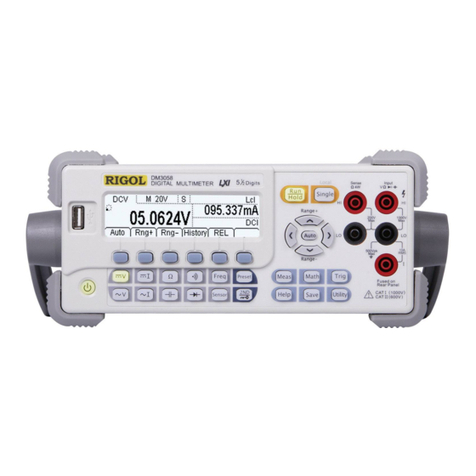
Rigol DM3058E User manual
Rigol
Rigol DM3058 Operating instructions
Rigol
Rigol DM3068 Installation and operation manual
Rigol
Rigol DM3000 Series Operating instructions
Rigol
Rigol DM3068-OB User manual

Rigol
Rigol DM3058 User manual
Rigol
Rigol DM3068 User manual

Rigol
Rigol DM3068 User manual
Rigol
Rigol DM3063 User manual
Rigol
Rigol DM3058 Operating instructions


