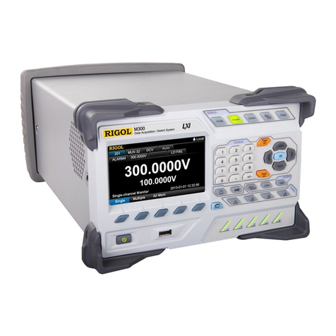
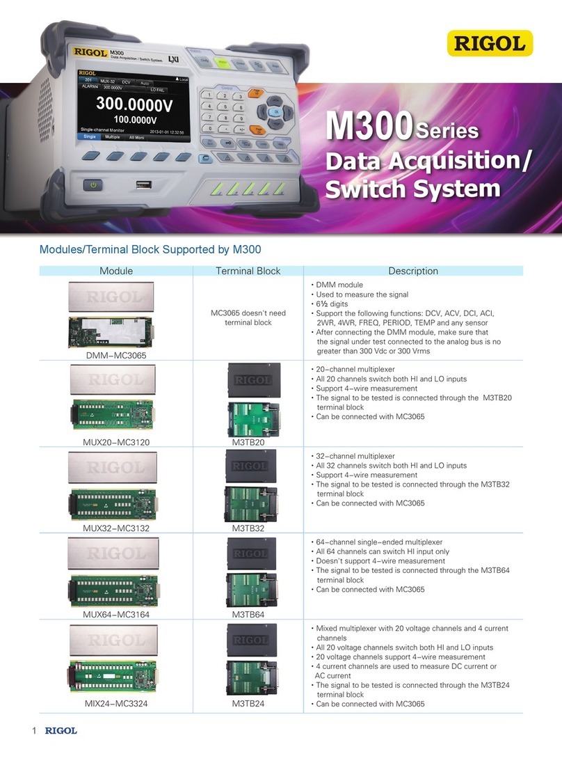
Rigol M300 Series User manual


RIGOL
M300 Selection Guide I
Contents
Document Overview.............................................................................................................1
M300 Overview....................................................................................................................1
M300 Options and Accessories.............................................................................................2
M300 Standard Accessories .................................................................................................3
Mixed-interface Separator Line ............................................................................................... 4
Fuse ....................................................................................................................................5
M300 Optional Accessories ..................................................................................................6
Modules and Terminal Blocks..................................................................................................6
Module Appearance Diagrams.......................................................................................... 6
To Connect the Module and Terminal Block........................................................................7
Connecting Cable Specification Requirements.................................................................... 9
DMM Module................................................................................................................ 10
Multiplexer and Terminal Block....................................................................................... 11
Actuator and Terminal Block........................................................................................... 24
Multifunction Module and Terminal Block......................................................................... 26
Matrix Switch and Terminal Block.................................................................................... 29
Other Optional Accessories................................................................................................... 33
RS232 Serial Cable........................................................................................................ 34
Analog Bus External Port ............................................................................................... 35
To Select Optional Accessories...........................................................................................36
Appendix: Temperature Sensor Selection Reference .........................................................37


RIGOL
M300 Selection Guide 1
Document Overview
This manual guides users to configure M300 series data acquisition/switch system so as to build the
measurement system according to their requirements. You can get a full understanding of the using
information of M300 series data acquisition/switch system via this manual together with the quick guide
and data sheet.
For the detailed specifications, please refer to
M300 Data Sheet
. For the product overview, please refer to
M300 Quick Guide
.
M300 Overview
M300 series data acquisition/switch system provides 5 slots and supports 8 kinds of plug-in modules
including DMM Module, Multiplexer, Matrix Switch and Multifunction Module. With its modular structure, it
combines precision measurement capability with flexible signal connections and can provide versatile
solutions for the applications that require multiple points or multiple signals to be tested. This can be
especially useful in product performance test during the R&D phase and automatic test during the
production process.
M300 provides a 4.3 inch high-resolution color LCD, user-friendly interface design, easy-to-use keyboard
layout as well as clear key backlight and operation prompts. M300 is extremely flexible and easy to use.
For remote control versatility, it comes with RS232, USB, LAN and GPIB interfaces.
Main Features:
Up to 320 switch channels per main frame (with very low cost per channel)
Can run independently without PC
Direct storage of data to USB storage device
Can store up to 100k time-stamped readings
8 modules supported
The 6½ digit DMM provided can be inserted into any slot. It supports DCV, DCI, ACV, ACI, 2WR, 4WR,
PERIOD, FREQ, TEMP (Thermocouple, Thermistor and RTD) and any sensor measurement functions.
Multiple standard communication interfaces, including USB Device, USB Host, GPIB, LAN (LXI Core
2011 Device) and RS232
Standard SCPI command set
Math statistic function: AVG, MAX, MIN and SDEV
User-friendly interface
On-line help system
Multiple system languages
4.3 inch color LCD
PC control and analysis software (Ultra Acquire)

RIGOL
2 M300 Selection Guide
M300 Options and Accessories
M300 series data acquisition/switch system provides the following options and accessories. To order the
desired options or accessories, please contact RIGOL or the local distributor. For the using method and
technical specifications of the M300 main frame, please refer to
M300 User's Guide
. This manual provides
detailed introductions of the using method of the options and accessories of M300 and guides users to
select the desired optional accessories.
Table 1 M300 Options and Accessories List
Description Ordering No.
Main Frame
M300 Data Acquisition/Switch System M300
M300 Data Acquisition/Switch System + DMM Module M301
M300 Data Acquisition/Switch System + DMM Module +
MC3120 20-Channel Multiplexer
M302
Standard
Accessories
Power Cord Conforming to the Standard of the Country
--
USB Cable
CB-USBA-USBB-FF-150
Mixed-interface Separator Line
MIX-SEPARATOR
Four Spare Fuses:
Two AC, 250 V, T250 mA fuses
Two AC, 250 V, T3.15 A fuses
--
Quick Guide
--
Resource CD (User’s Guide and Ultra Acquire)
--
Optional
Accessories:
Module
DMM Module (6½ digits)
MC3065
20-channel Multiplexer
MC3120
32-channel Multiplexer
MC3132
64-channel Single-ended Multiplexer
MC3164
20-voltage-channel + 4-current-channel Mixed
Multiplexer
MC3324
16-channel Actuator
MC3416
Multifunction Module
MC3534
4×8 Matrix Switch
MC3648
Optional
Accessories:
Terminal
Block
MC3120 Terminal Block
M3TB20
MC3132 Terminal Block
M3TB32
MC3164 Terminal Block
M3TB64
MC3324 Terminal Block
M3TB24
MC3648 Terminal Block
M3TB48
MC3534 Terminal Block
M3TB34
MC3416 Terminal Block
M3TB16
Optional
Accessories
RS232 Serial Cable
-
GPIB Invert Port
M3GPIB
Analog Bus External Port
A-BUS-EXT-PORT
Rack Mount Kit[1]
RM-1-M300
Rack Mount Kit for Two Instruments[1]
RM-2-M300
PC Application Software for M300 Series[1]
Ultra Acquire
Note[1]: For the detailed information, please refer to the corresponding manuals (download them from RIGOL website
(www.rigol.com)).

RIGOL
M300 Selection Guide 3
M300 Standard Accessories
Power Cord USB Cable
Mixed-interface Separator Line Fuse
Quick Guide Resource CD

RIGOL
4 M300 Selection Guide
Mixed-interface Separator Line
The mixed-interface separator line is used to convert the [RS-232/Alarms/Ext Trig] interface (25-pin
male) at the rear panel to two 9-pin interfaces. Wherein, one is a 9-pin male interface used as a standard
RS232 interface and the other is a 9-pin female interface used for alarm output and external trigger signal
input.
RS232: connect this interface with the PC via a RS232 serial cable (optional accessory) to build the
communication between M300 and the PC. You can program and control the instrument via the PC.
RS232 Interface
Alarms/Ext Trig: as shown in the figure below, pin 1 to pin 4 are used to output TTL pulse when an alarm
is generated in the corresponding alarm channel. Pin 6 is used to receive the external trigger signal.
When an external digital multimeter is connected for measurement, pin 5 and pin 6 are used together to
control the measurement.
Alarms/Ext Trig Interface
Pin
Definition
1
Alarm 1 Output
2
Alarm 2 Output
3
Alarm 3 Output
4
Alarm 4 Output
5
Channel Closed Output
6
Ext Trig Input/Channel Advance Input
7
GND
8
Not Used
9
Not Used
6
7
4
5
2
3
1
6
7
4
5
2
3
1
8
9
Pin
Name
Definition
1
--
--
2
RXD
Received Data
3
TXD
Transmitted Data
4
DTR
Data Terminal Ready
5
SGND
Signal Ground
6
DSR
Data Set Ready
7
RTS
Request To Send
8
CTS
Clear To Send
9
--
--
8
9
[RS-232/Alarms/Ext Trig] Interface

RIGOL
M300 Selection Guide 5
Fuse
The AC, 250V, T250mA fuse is the alternate power supply fuse for the DMM module; the AC, 250V, T3.15A
fuse is the alternate power supply fuse, as shown in the figure below.
The AC power supply connected via the power socket is divided into two paths with one path providing
power for the DMM module and the other path providing power for the other circuits. M300 provides the
power supply fuse and independent power supply fuse of the DMM module.
To replace the fuses, follow the methods below.
Replace the power supply fuse of the DMM module
1) Turn off the instrument and remove the power cord.
2) Press down the fuse cap using a straight screwdriver and rotate the screwdriver clockwise.
3) Select the correct voltage scale at the voltage selector.
4) Remove the fuse cap and fuse.
5) Replace the old fuse with a specified fuse and reinstall the fuse cap.
CAUTION
To avoid electric shock or fire, please use the specified fuse.
Replace the power supply fuse
1) Turn off the instrument and remove the power cord.
2) Insert a small straight screwdriver into the slot at the power socket and pry out the fuse seat.
3) Replace the old fuse with a specified fuse.
4) Reinstall the fuse seat into the slot.
CAUTION
To avoid electric shock or fire, please use the specified fuse and make sure that the
fuse seat is not short-circuited.
Power Supply Fuse of the DMM Module
AC, 250V, T250mA
Power Supply Fuse
AC, 250V, T3.15A

RIGOL
6 M300 Selection Guide
M300 Optional Accessories
Modules and Terminal Blocks
Module Appearance Diagrams
M300 provides 8 kinds of modules, including the DMM module, 20-channel multiplexer, 32-channel
multiplexer, 64-channel single-ended multiplexer, multi-function module and etc. The appearance
diagrams of the modules are as shown in the figures below.
Figure 1 Module Appearance Diagrams
Golden Circuit board Edge: each on the
top and bottom for sliding into the slot
Interface 1: 78Pin interface; connect the
signal under test via the terminal block (the
DMM module does not have this interface)
Interface 2: connect
with the main frame

RIGOL
M300 Selection Guide 7
To Connect the Module and Terminal Block
Multiple signals to be measured can be connected to the plug-in modules through the external terminal
blocks and then switched to the DMM module or external DMM.
WARNING
Cut off all the power supplies before opening the terminal block or removing the terminal
block from the module.
1. Place the terminal block with the front side (with the RIGOL caption) facing downward; pull the two
latches in the arrow direction in the figure below and press them down. Place the terminal block with
the front side facing upward; pull the upper cover of the terminal block upward and remove it.
Figure 2 Disassemble the Upper Cover of the Terminal Block
2. Connect the cables for connecting the signal under test according to the labels on the circuit board of
the terminal block. Pass the binding wires through the two groups of holes as pointed out by the
arrows in the figure below to fix the cables connected. Pay attention to the channel or terminal
connected to the cable to ensure that the signal connected is correct.
Note: For the layout and connection methods of the terminals of each terminal block as well as the
specification requirements of the connecting cables, refer to the introductions in the later sections.
Figure 3 Internal Structure Diagram of the Terminal Block
3. Connect the terminal block to the module via interface 1 (namely the 78Pin interface; for the
interface definition, refer to Figure 1) on the module and screw down the two screw rods onto the
nuts on the module.

RIGOL
8 M300 Selection Guide
Figure 4 Connect the Terminal Block and Module
4. Close the upper cover of the terminal block.
Figure 5 Close the Upper Cover of the Terminal Block
5. Insert the module connected with the terminal block into the slot of the mainframe. As shown in
Figure 1, there is a golden circuit board edge both on the top and bottom of the module. Aim the two
edges with the sliding chutes in the main frame slot and push the module in until you hear a sound.
At this point, interface 2 (for the interface definition, refer to Figure 1) is connected to the main
frame.
Figure 6 Insert the Module Connected with the Terminal Block into the Main Frame Slot
Note:
All the modules of M300 do not support hot-plugging. Therefore, please turn the main frame off
before inserting the modules into the main frame.

RIGOL
M300 Selection Guide 9
Connecting Cable Specification Requirements
To reduce the error caused by the connecting cables, 14AWG to 24AWG conducting wires are required.
You are recommended to use conducting wire with 6.5mm stripping length. The diameter, area and
copper impedance of each kind of conducting wire are as shown in the table below.
Note: The "Copper Impedance" in the table below refers to the DC impedance of the single-direction
copper wire under 25℃. The temperature coefficient of the copper wire is 0.35%/℃. When a pair of
copper wires is used, the impedance value doubles.
Table 2 Recommended Cable Specifications
AWG
Diameter (mm)
Area (mm2)
Copper Impedance (Ω/km)
14
1.628
2.08
8.286
15
1.45
1.65
10.45
16
1.291
1.31
13.17
17
1.15
1.04
16.61
18
1.024
0.823
20.95
19
0.912
0.653
26.42
20
0.812
0.518
33.31
21
0.723
0.41
42
22
0.644
0.326
52.96
23
0.573
0.258
66.79
24
0.511
0.205
84.22

RIGOL
10 M300 Selection Guide
DMM Module
The DMM module (MC3065) is used to measure the signals under test and has 6½ digit reading
resolution. The measurement functions include DCV, ACV, DCI, ACI, 2-wire resistance, 4-wire resistance,
frequency, period, temperature and any sensor. After connecting the DMM module, make sure that the
signal under test connected to the analog bus is no greater than 300Vdc or 300Vrms.
The DMM module is as shown in the figure below. The DMM module does not have interface 1 (namely
the 78Pin interface; for the interface definition, refer to Figure 1).
Figure 7 MC3065

RIGOL
M300 Selection Guide 11
Multiplexer and Terminal Block
M300 provides 4 kinds of multiplexer modules as well as 4 kinds of external terminal blocks for the
multiplexer modules to connect the signals under test in 1-wire, 2-wire and 4-wire connection modes.
Table 3 Multiplexers and the Corresponding Terminal Blocks and Connection Modes
Module
Terminal Block
Supported Connection Mode
MC3120
M3TB20
2-wire and 4-wire
MC3132
M3TB32
MC3164
M3TB64
1-wire
MC3324
M3TB24
2-wire and 4-wire
1. MC3120 and M3TB20
MC3120 is a 20-channel multiplexer. All the 20 channels switch both HI and LO inputs, thus providing
fully isolated signals for the DMM module. MC3120 is divided into two banks (called A and B) with 10
two-wire channels for each bank. When making 4-wire resistance measurement, the instrument
automatically pairs the channels of A bank and B bank. All the channels added into the scan list are
break-before-make. You can close multiple channels on this module when you have not configured
any channel to be part of the scan list.
MC3120 can be connected with MC3065 (the DMM module, if MC3065 is currently inserted).
For the technical specifications of this module, please refer to the User’s Guide or Data Sheet of this
product.
MC3120 is as shown in the figure below.
Figure 8 MC3120
M3TB20 is an external terminal block applicable to MC3120. Its appearance and detailed layout are
as shown in the figure below. There are 20 pairs of connecting terminals from the lower-left corner
to the upper-right corner corresponding to the 20 channels of MC3120 respectively. The connecting
terminals can be recognized via the labels (CH01 to CH20) below or above them.
Figure 9 M3TB20

RIGOL
12 M300 Selection Guide
The figure below is the schematic diagram of MC3120 and M3TB20.
Figure 10 MC3120 Schematic Diagram
The definitions of the pins of the 78Pin interface of MC3120 are as shown in the figure below.
Pin Label
Pin Qty.
Definition
HI_n[1]
20
Correspond to the 20-channel
differential positive input
terminal on the external
terminal block
LO_n[1]
20
Correspond to the 20-channel
differential negative input
terminal on the external
terminal block
NC
28
Connection is forbidden
EX_HI
1
Correspond to the 2-W HI
terminal on the external
terminal block
EX_LO
1
Correspond to the 2-W LO
terminal on the external
terminal block
EX_HS
1
Correspond to the SENSE HI
terminal on the external
terminal block
EX_LS
1
Correspond to the SENSE LO
terminal on the external
terminal block
+5V
2
Connected to the digital
temperature sensor (I2C type)
on the external terminal block
DGND
2
SDA
1
SCL
1
Note[1]: n is an integer from 01 to 20.

RIGOL
M300 Selection Guide 13
2. MC3132 and M3TB32
MC3132 is a 32-channel multiplexer. All the 32 channels switch both HI and LO inputs, thus providing
fully isolated signals for the DMM module. MC3132 is divided into two banks (called A and B) with 16
two-wire channels for each bank. When making 4-wire resistance measurement, the instrument
automatically pairs the channels of A bank and B bank. All the channels added into the scan list are
break-before-make. You can close multiple channels on this module when you have not configured
any channel to be part of the scan list.
MC3132 can be connected with MC3065 (the DMM module, if MC3065 is currently inserted).
MC3132 is as shown in the figure below.
Figure 11 MC3132
M3TB32 is an external terminal block applicable to MC3132. Its appearance and detailed layout are
as shown in the figure below. There are 32 pairs of connecting terminals from the lower-left corner
to the upper-right corner corresponding to the 32 channels of MC3132 respectively. The connecting
terminals can be recognized via the labels (CH01 to CH32) below or above them.
Figure 12 M3TB32

RIGOL
14 M300 Selection Guide
The figure below is the schematic diagram of MC3132 and M3TB32.
01 H
L
H
L
...
H
L
H
L
...
DMM
Source
H
L
DMM
Sense
H
L
16
17
32
Bank Switch
Channel Switches
98
99
97
Backplane Switches
H
L
Com
(4W Sense)
H
L
Com
Signals
to be
Measured
Reference
Junction
Terminal Block: M3TB32
H
L
01
H
L
32
.
.
.
78-Pin
Interface
Figure 13 MC3132 Schematic Diagram

RIGOL
M300 Selection Guide 15
The definitions of the pins of the 78Pin interface of MC3132 are as shown in the figure below.
Pin Label
Pin Qty.
Definition
HI_n[1]
32
Correspond to the 32-channel
differential positive input terminal
on the external terminal block
LO_n[1]
32
Correspond to the 32-channel
differential negative input terminal
on the external terminal block
NC
4
Connection is forbidden
EX_HI
1
Correspond to the 2-W HI terminal
on the external terminal block
EX_LO
1
Correspond to the 2-W LO terminal
on the external terminal block
EX_HS
1
Correspond to the SENSE HI
terminal on the external terminal
block
EX_LS
1
Correspond to the SENSE LO
terminal on the external terminal
block
+5V
2
Connected to the digital
temperature sensor (I2C type) on
the external terminal block
DGND
2
SDA
1
SCL
1
Note[1]: n is an integer from 01 to 32.

RIGOL
16 M300 Selection Guide
3. MC3164 and M3TB64
MC3164 is a 64-channel single-ended multiplexer. All the 64 channels can switch the HI input only.
MC3164 is divided into two banks (A and B) with 32 single-ended channels for each bank. All the
channels added into the scan list are break-before-make. In any case, you cannot close multiple
channels on this module.
MC3164 can be connected with MC3065 (the DMM module, if MC3065 is currently inserted). MC3164
cannot be used for 4-wire resistance measurement.
MC3164 is as shown in the figure below.
Figure 14 MC3164
M3TB64 is an external terminal block applicable to MC3164. Its appearance and detailed layout are
as shown in the figure below. The 64 connecting terminals correspond to the 64 channels of MC3164
respectively. The connecting terminals can be recognized via the labels (01 to 64) below or above
them. This terminal block does not support 4-wire connection.
Figure 15 M3TB64
Other manuals for M300 Series
3
This manual suits for next models
3
Table of contents
Other Rigol Switch manuals
Popular Switch manuals by other brands

Extron electronics
Extron electronics VGA MATRIX SWITCHERS MVX PLUS 128 user manual

Sunricher
Sunricher SR-ZGP2801K4-DIM-S2-E instruction manual

GE
GE CWLSWDMBWF1 installation guide

Omega Engineering
Omega Engineering PSW-180 Series instruction sheet

Ozito
Ozito PSA-001 instruction manual

Ubiquiti
Ubiquiti USW--Pro--48 quick start guide