Riken Keiki FI-21 User manual

FI-21
Operator’s Manual
Optical Gas Indicator

Warning
Read and understand this instruction manual
before operating instrument. Improper use of
the gas monitor could result in bodily harm or
death.
Periodic calibration and maintenance of the gas
monitor is essential for proper operation and
correct readings. Please calibrate and maintain
this instrument regularly! Frequency of
calibration depends upon the type of use you
have and the sensor types. Typical calibration
frequencies for most applications are between 1
and 3 months, but can be required more often or
less often based on your usage.
Contact Information
http://www.gastech.com.au
24 Baretta Rd
Wangara Western Australia 6065
GasTech Australia Pty Ltd
Fax 1800 999 903
Tel 1800 999 902

Warranty
Control Equipment Pty Ltd warrants gas alarm equipment sold by us to be free from defects in
materials, workmanship, and performance for a period of one year from date of shipment from
Control Equipment Pty Ltd. Any parts found defective within that period will be repaired or replaced,
at our option, free of charge. This warranty does not apply to those items, which by their nature, are
subject to deterioration or consumption in normal service, and which must be cleaned, repaired, or
replaced on a routine basis. Examples of such items are as follows:
Absorbent cartridges
Batteries
Pump diaphragms and valves
Filter elements
Fuses
Warranty is voided by abuse including mechanical damage, alteration, rough handling, or repair
procedures not in accordance with the operator’s manual. This warranty indicates the full extent of
our liability, and we are not responsible for removal or replacement costs, local repair costs,
transportation costs, or contingent expenses incurred without our prior approval.
THIS WARRANTY IS EXPRESSLY IN LIEU OF ANY AND ALL OTHER WARRANTIES AND
REPRESENTATIONS, EXPRESSED OR IMPLIED, AND ALL OTHER OBLIGATIONS OR LIABILITIES ON
THE PART OF CONTROL EQUIPMENT PTY LTD, INCLUDING BUT NOT LIMITED TO, THE
WARRANTY OF MERCHANTABILITY OR FITNESS FOR A PARTICULAR PURPOSE. IN NO EVENT
SHALL CONTROL EQUIPMENT PTY LTD BE LIABLE FOR INDIRECT, INCIDENTAL, OR
CONSEQUENTIAL LOSS OR DAMAGE OF ANY KIND CONNECTED WITH THE USE OF ITS
PRODUCTS OR FAILURE OF ITS PRODUCTS TO FUNCTION OR OPERATE PROPERLY.
This warranty covers instruments and parts sold to users by authorized distributors, dealers, and
representatives as appointed by Control Equipment Pty Ltd.
We do not assume indemnification for any accident or damage caused by the operation of this gas
monitor, and our warranty is limited to the replacement of parts or our complete goods.

Contents
WARRANTY.................................................................................................................................................................. 3
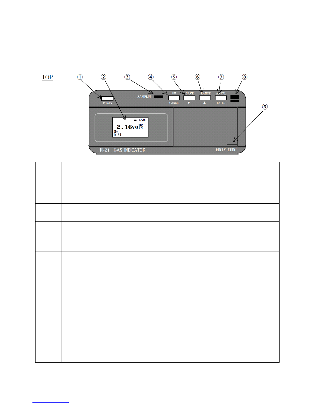
1.0 PARTS AND FUNCTION .................................................................................................................................... 7
2.0 MEASURING MODE (POWER KEY) ................................................................................................................... 9
2.1 Basic Display for Measuring Mode and Explanation........................................................................................ 9
2.2 Procedures from Power ON to Measurement .............................................................................................. 10
2.3 Saving Data ................................................................................................................................................... 12
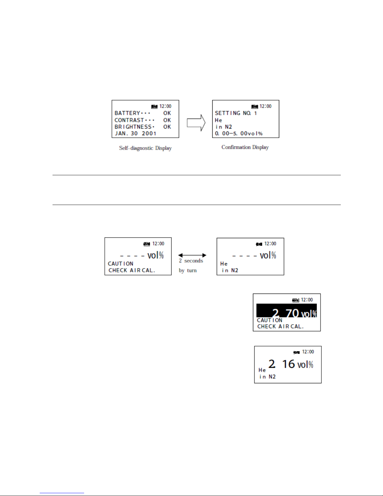
2.4 Initial Display (Self-diagnostic Display) ......................................................................................................... 12
2.6 AIR CAL. CAUTION ......................................................................................................................................... 12
2.7 Affection on Measurement from Pressure ................................................................................................... 13
3.0 SETTING MODE (ENTER + POWER) ................................................................................................................ 15
3.1 Changing the Measuring Gas (SELECT GAS) ................................................................................................... 15
3.2 Adjusting the Time (SET DATE / TIME)........................................................................................................... 16
3.3 Confirming the Saved Data (VIEW SAVED DATA)........................................................................................... 16
3.4 Clearing the Saved Data (CLEAR SAVED DATA) .............................................................................................. 16
3.5 Start the Measurement (START MEAS. ).................................................................................................. 16
4.0 MAINTENANCE.............................................................................................................................................. 17
4.1 Replacing the Batteries ................................................................................................................................. 17
4.2 Confirming the Sensitivities........................................................................................................................... 17
4.3 Daily Check.................................................................................................................................................... 17
4.4 Frequency / Standard for Replacing Parts ..................................................................................................... 17
5.0 DISPOSING THE INSTRUMENT ....................................................................................................................... 18
6.0 TROUBLE SHOOTING ..................................................................................................................................... 18
7.0 CAUTION OF USAGE ...................................................................................................................................... 19
8.0 DEFENITION OF TERMS ................................................................................................................................. 20
9.0 SPECIFICATIONS ............................................................................................................................................ 21
9.1 Specifications ................................................................................................................................................ 21
9.2 Standard Accessories .................................................................................................................................... 22

10.0 MEASURING PRINCIPLE............................................................................................................................. 23
11.0 TYPE-01 SPECIFICATIONS.......................................................................................................................... 24
12.0 TYPE-02 SPECIFICATIONS.......................................................................................................................... 25
13.0 TYPE-03 SPECIFICATIONS.......................................................................................................................... 26
14.0 TYPE-04 SPECIFICATIONS.......................................................................................................................... 27
15.0 TYPE-05 SPECIFICATIONS.......................................................................................................................... 28

The Riken Gas Indicator Model FI-21 is a precision gas analyser which is adapted to measure the % volume
concentration of any of the commonly used gas in a mixture of air or oxygen for solvents, fumigation, gas
purity and anaesthetic gas.
The standard instrument is calibrated for eight selectable gas readings on the direct digital display.
The FI-21 operating principle utilises the highly accurate measurement with CCD and Fourier analysis
technology and electronic circuitry to provide direct digital readout.
The FI-21 is equipped with a built-in sample draw pump for ease of use.
This instruction manual is a guidebook how to operate the Model FI-21. Not only beginner users but also
experienced users have to read this manual and start the operation after understanding the contents well.
This instrument is to be used for the purposes listed in this manual and the attached measuring gas
specifications.
For your Safety - the following marks are applied in this manual.
DANGER: It means the matter that causes a serious damage on human beings directly.
WARNING: If the instrument is operated not following by the manual, it causes a serious damage on
human beings or objects.
CAUTION: If the instrument is operated not following by the manual, it causes some damage on human
beings or objects.
NOTE: Manufacturers advisory comment
As the kinds of measurable gas and range are different depending on the type of FI-21, refer to the attached
measuring gas specification. For standard models, refer to the attached “each TYPE measuring gas
specification”.

1.0 Parts and Function
1
POWER key:
Press this key to turn the power on until buzzer beeping. Keep pressing the key approx. 3 seconds to turn
the power off. When pressing the POWER key and (7) ENTER key, you can enter the “SETTING MODE”.
2
LCD Display:
Concentration is displayed. And also, time, battery remainder, measuring gas and base gas are displayed.
3
LED for “SAMPLING”:
While the internal pump is working, this LED is on.
4
PUMP key (CANCEL):
When this key is pressed once, the internal pump starts to work. When the key is pressed
again, the pump stops.
(Contents selected by 「▼, ▲keys」are cancelled by this key.)
5
SAVE key (▼key ):
Information about Time/ Date, Measuring Gas, Base Gas, Displayed Concentration is saved by this key. The
maximum number of data points is 100.
(This key is used to enter numbers or to move the cursor.)
6
RANGE key (▲key):
Position of the decimal point on the concentration display can be moved by this key.
(This key is used to enter numbers or to move the cursor.)
7
AIR CAL. Key (ENTER key):
When calibration is performed with standard gas, this key is used.
(Contents selected by 「▼, ▲keys 」are fixed by this key.)
8
Buzzer:
It beeps when the power turns on/off, or when special control or wrong operation is performed.
9
There is a data logger interface under the cover.
* Explanations in the ()are for use during SETTING MODE.

10
Inlet for measuring gas. A specific absorption tube must be connected to the inlet.
Otherwise, the reading might go wrong.
11
Outlet connected to the reference gas chamber. The exhaust from the outlet has to be emitted into
the fresh air at atmospheric pressure.
12
Outlet for measuring gas sucked from the GAS IN.
13
6VDC Interface for the specific AC adaptor.
14
A jack for 0-1VDC output. (cable : option)
15
Cover for the battery box.
16
Fixing screw for the battery cover. It can be open/ close by a screwdriver or coin.
Tubing Structure

2.0 MEASURING MODE (POWER KEY)
2.1 Basic Display for Measuring Mode and Explanation
Display Contents
Status
Gas Name and
Base Gas
Usual measuring mode.
CAUTION
CHECK AIR CAL.
Zero drifting might be occurring. Let the monitor sample the fresh air and
perform AIR CAL.
CAUTION
ABNORMAL
TEMP.
Internal thermistor detects an abnormal temperature.
CAUTION
LOW BATT.
Battery voltage is low. Replace the batteries.
CAUTION
LOW CONTRASUT
Interferometer sensor is getting contaminated. Before the measurement is
performed, the sensor should be replaced or repaired.
CAUTION
LOW BRIGHTNESS
Brightness is getting low. Before the measurement is performed, the sensor
should be replaced or repaired.
CAUTION: When a message “CAUTION ” appears on the LCD, make an appropriate procedure as soon as
possible.

2.2 Procedures from Power ON to Measurement
a) Power turns on by pressing the POWER key until buzzer beeps. And, the initial display (self-diagnostic display)
shows up. It then turns to a display to confirm the setting. After showing the confirmation display for 2
seconds, it goes to the basic display of measuring mode.
CAUTION: This instrument does not indicate a correct reading if the measuring gas and base gas are not
selected properly. Confirm if [Measuring Gas] and [Base Gas] are the ones intentionally selected.
b) After that, two of the messages, [Meas Gas/ Base Gas] and [Air CAL], are displayed by turn as below.
(Refer to WARNIN AIR CAL.)
c) Press the PUMP Key and let it sample enough reference gas (fresh air).
(The color of the display reverses while the pump is operating.)
d) After the indication becomes stable, stop the pump and keep pressing
the AIR CAL key until buzzer beeps.

e) After AIR CAL., set the instruments so that it can monitor objective gas, and press PUMP key. The color of the
display reverses while the pump is operating. Indication while the pump operating is not the result of
monitoring.
f) Press PUMP key and stop the pump after indication become stable, and read the indication.
The indication under the condition that the pump and sample gas flow have stopped is the monitoring result.
CAUTION: Press AIR CAL key after confirming there is enough fresh air in the chamber. Otherwise,
correct measurement cannot be performed.
* NOTE: If the [AIR] is selected as the base gas, the indication shows zero when the AIR CAL key is
pressed. However, If the [N2] or other gases except [AIR] is selected as the base gas, the
indication does not show zero, but other values determined based on the combination of
the measuring gas and the base gas. This is caused by sampling the gas which is not on
target. (In this case, it is air.) Do not think it broken. Once the instrument samples the
target gas, it shows a correct reading. Depending on the combination of the measuring gas
and the base gas, AIR CAL value may be negative value (minus value). For further
information, refer to the measuring gas specification.
CAUTION: FI-21 performs best when both Gas Chamber and Reference Chamber are at the
atmospheric pressure (101.3kPa). While the measuring gas is being sampled, the pressure
in the Gas Chamber becomes slightly different from the atmospheric pressure, and the
analyzer does not show the correct reading. Read the indication after the gas flow stops.
* NOTE: FI-21 measures the gas best when both Gas Chamber and Reference Chamber are at
101.3kPa. If precise measurement is required, perform the pressure correction by the
following method.

2.3 Saving Data
Once the SAVE key is pressed, the buzzer beeps and the display shown on the right
comes up. The time/ data and the measurement result are saved chronologically
from No.001 to No.100. The saved data can be seen at “VIEW SAVED DATA” in the
SETTING MODE. Also, the saved data is deleted at “CLEAR SAVED DATA” in the
SETTING MODE.
2.4 Initial Display (Self-diagnostic Display)
At starting with the MEASURING MODE by pressing POWER Key the self-diagnostic
function automatically starts to work. If the result is normal, display shown on the
right side is displayed.
If any problem was found on any of the items, it is indicated like the display on the
right. The display is an example for contamination of the interferometer. If the
problem becomes serious, the display does not go to the Basic Display of the
Measuring Mode, but go to ERROR message display.
2.6 AIR CAL. CAUTION
If the temperature inside of the sensor has changed over ± 10℃from the last time the AIR CAL was performed,
[CAUTION/ CHECK AIR CAL] is displayed in order to protect from zero drifting. ([Measuring Gas/ Base Gas] and [AIR CAL]
are displayed consecutively.
If the [CAUTION/ CHECK AIR CAL]: is displayed, perform the AIR CAL based on the procedure below:
AIR CAL. Procedure
1. Press the PUMP key and let it sample some fresh air.
2. When the indication becomes stable, stop the pump with PUMP key and press the AIR CAL key.
CAUTION: Before pressing the AIR CAL key, let the instrument sample enough fresh air. (ideally for 2 minutes )
Otherwise, correct measurement cannot be performed.
CAUTION: Whenever measurement starts, confirm if the AIR CAL value is displayed after fresh air is sampled
enough. If the AIR CAL. Value is not indicated (or even if [AIR CAL CAUTION] is not displayed),
perform the AIR CAL procedures by correct method.

2.7 Affection on Measurement from Pressure
The pressure in the Gas Chamber becomes different from the atmospheric pressure whiling sampling the gas. As a
result, the indication is not accurate. Or, if an instant pressure change occurs in the Gas Chamber or the Reference
Chamber, the indication might go wrong. (If these symptoms occur, perform the AIR CAL right away.) Therefore, take
care about the following points:
Do not plug the GAS IN or GAS OUT while gas is feeding.
Do not attach and detach sampling tube/absorption tube while gas is feeding.
Keep the pressure of GAS IN, GAS OUT, and REF. OUT equal to the atmospheric pressure when the indication is
read.
Read the indication after the gas flow stops.
CAUTION: When concentration change occurs suddenly on the FI-21, correct reading cannot indicate.
Absorption tube is also for stabilizing the temperature of the sampling gas. Therefore, equip an
absorption tube on the GAS IN whenever the measurement is performed.
CAUTION: Whenever measurement starts, confirm if the AIR CAL value is displayed after fresh air is sampled
enough. If the AIR CAL. Value is not indicated (or even if [AIR CAL CAUTION] is not displayed),
perform the AIR CAL procedures by correct method.
An example of measurement when the pressure of the sampling point is higher than the atmospheric pressure:
Make an inlet (a) as the drawing below. Open and shut the stop valve to feed the gas to the instrument,
instead of turning the pump on and off. Read the indication after shutting the valve off and the gas flow totally
stops. Flow rate at Inlet (a) should be 300 to 400mL.
GAS OUT should be at the atmospheric pressure and the REF. OUT should face with fresh air.

An example of measurement when the measured gas is not released in to the air:
Connect a gas sampling bag to the GAS OUT, not to emit the exhaust into the air. And also, expose the REF.
OUT to the fresh air.

3.0 SETTING MODE (ENTER + POWER)
The SETTING MODE is for “Change the Measuring Gas”, “Adjusting the
Time”, and “Confirming the Saved Data”. You enter the SETTING MODE
by pressing the POWER key while the ENTER key is being pressed.
Once you enter the mode, the display on the right shows up.
Move the cursor (black bar) by ▼▲keys and select the item which you
would like to setup. Go into the item by [ENTER key].
Items to Setup and the Contents
SELECT GAS
Changing the measuring gas
SET DATE/ TIME
Adjusting the clock
VIEW SAVED DATA
Confirming saved data
CLEAR SAVED DATA
Clearing the saved data
START MEAS.
Starting the Measuring Mode.
3.1 Changing the Measuring Gas (SELECT GAS)
Choose the measuring gas by the [▼▲] key and press ENTER key to fix the choice. On the 1st line, a sentence “IS
SETTING OK?” appears. Press [ENTER] key again if it is okay. If you want to change the setting, press the [CANCEL] key.
The kinds of selectable measuring gas and range are different depending on the type of FI-21. For the information, refer
to the attached measuring gas specification.

3.2 Adjusting the Time (SET DATE / TIME)
Initial position of the cursor is on YEAR. Choose by ▼▲keys and fix the setting by
the ENTER key. The cursor then moves to DAY. Set DAY, YEAR, HOUR and MINUTE
by the same procedures as MONTH. HOUR is displayed by 24 hour clock.
3.3 Confirming the Saved Data (VIEW SAVED DATA)
On the 1st line, the data number is shown. On the 2nd to 3rd line, the saved date/ time are displayed.
Select the date number by [▼▲] key and fix the selection by [ENTER] key. The saved data then comes up. (At
displaying the saved data, the measuring gas and the base gas is displayed with white letters on black background.)
(CANCEL key leads to the initial display in Setting Mode.)
3.4 Clearing the Saved Data (CLEAR SAVED DATA)
Select the “CLEAR SAVED DATA” by ▼▲ key and fix the selection by
ENTER key. If you want to cancel the action, select “CANCEL” and
press the [ENTER] key.
3.5 Start the Measurement (START MEAS. )
If you want to start the measurement right after setting each item,
select “START MEAS” by ▼▲ key and press [ENTER] key. The display
will then go to the Measuring Mode.

4.0 MAINTENANCE
4.1 Replacing the Batteries
WARNING: - All the C size Alkaline batteries used in the instrument should be same kind.
-Replace the 4 of the batteries at the same time.
a) Confirm that the power is off.
b) Take out the instrument from the carrying case.
c) Take off the battery cover under the bottom by turning the screw with a coin.
d) Take out the old batteries and put the new ones caring the polarities.
e) When the replacement is done, put the battery cover on the bottom by the opposite procedures.
4.2 Confirming the Sensitivities
It is recommended that the sensitivity of the instrument be confirmed periodically (at least once a year) to assume
the correct operation. If any problem is found, or If you would like to have it calibrated, please contact Control
Equipment Pty Ltd.
4.3 Daily Check
a) Is there any damage on switches, lamps, display or body?
b) Confirmation of battery voltage.
c) Do you see “CAUTION …” or “ ERROR…” during the operation?
4.4 Frequency / Standard for Replacing Parts
The frequency of the replacement mentioned below is just a standard. The available term totally depends on how
often the instrument is used and how it is stored.
a) Internal pump and internal tubing - 2 years
b) Absorption Tube (consumable part) - 2 years
c) Rubber parts in Interferometer - 2 years (Optic element should be cleaned if necessary.)
d) Main PCB - 5 years
e) Interferometer Assembly - 5 years (continuously used if no problem.)
f) Others - 5 years

5.0 DISPOSING THE INSTRUMENT
This instrument does not apply any harmful material as component parts. When the instrument is disposed, take an
appropriate method based on the local regulation.
6.0 TROUBLE SHOOTING
Trouble shootings mentioned below do not cover all the problems. The ones considered frequently occur are simply
indicated to help your research for cause and solution.
Symptoms
Causes
Solutions
Power does not turn ON.
No batteries.
Or, AC adaptor is not connected.
Polarity of the batteries is wrong.
Time to press the POWER Key is
short.
Put the batteries in.
Or, connect AC adaptor.
Put the batteries in correct
direction.
Keep pressing the POWER key
until the buzzer beeps.
Reading is not correct.
AIR CAL is not performed in a
correct way.
The selected “Measuring Gas” or
“Base Gas” is wrong.
Interference gas is included in the
sample gas.
A sudden pressure change occurs
at GAS IN, GAS OUT or REF. OUT.
The pressure at GAS IN, GAS OUT
or REF. OUT is not at atmospheric
pressure.
When the instrument samples
enough fresh air, stop the pump.
Then, press the AIR CAL key.
Select the correct “Measuring
Gas” and “Base Gas”. The target
gas that contains interference gas
cannot be measured.
Perform AIR CAL again.
Set GAS IN, GAS OUT and REF.
OUT under the atmospheric
pressure.
After performing AIR CAL, the
reading goes up even though any
gas is not fed.
Molecular attached to the
chamber inside or tubing inside
starts detaching.
The concentration in chamber
becomes high in fact.
Let the instrument sample enough
fresh air.
And confirm if it shows the AIR
CAL value.

7.0 CAUTION OF USAGE
DANGER:
The following caution items must be followed to maintain the performance/ safety of the instrument.
Specification of this instrument is based on a non-explosion structure. Do not use it in a place specified as a
hazardous area.
Make any solutions for exhaust gas emitted from GAS OUT, to avoid harmful gas from emission. (e.g.
Connecting a sampling bag to GAS OUT.)
Just in case of leaking from the instrument itself, wearing a mask and gloves is recommended.
WARNING:
The instrument shows incorrect indication when it samples a high concentration gas over the full scale.
Use the batteries based on the specifications.
Use the specified AC adaptor if necessary.
CAUTION:
Do not use this instrument close to other apparatus that generates a strong noise. It may affect the wave form
of the power source. If the AC adaptor is applied, do not use the same power source as other apparatus that
generates a strong noise.
Use the power source based on the specifications.
Do not operate the instrument in a place which has a reaction heat such as infrared emitted from high
temperature. Or, Avoid a place which has a direct sunbeam that makes the instrument over 35C.
Interference Gas: The gases which are neither the target gas nor base gas. If there is any interference gas in
the measuring gas, the reading goes wrong. Do not measure the gas which contains interference gas.
Let GAS OUT and REF. OUT expose to the air, in order to equal the pressure inside to the atmospheric
pressure.
Whenever this instrument operates, keep it in a carrying case and connect the absorption tube.

8.0 DEFENITION OF TERMS
Terms
Description
vol%
The rate of substance occupying in some volume.
The unit is indicated by percentage.
ppm
The rate of substance occupying in some volume.
The unit is indicated by ppm “parts per million”.
%LEL
This is the unit when defining the Lower Explosive Limit of a combustible gas as
100%.
mg/l
This is the unit of the target gas mass that is contained in one litter.
The standard is under the condition of 20℃, 101.3kPa.
MJ/m3
Gross
This is the unit of calorie, and it is indicated by gross calorific value 0℃.
Gross calorific value 0 ℃is common calorie unit among city gas companies. It
is equal to the calorie in case of complete combustion of a gas 1m3 under the
standard condition (0℃, 1pressure).
Gas combustion generates steam.
Gross calorific value includes the calorie of the steam (latent heat).
MJ/m3
Net
This is the unit of calorie, and it is indicated by net calorific value 0℃.
Net calorific value 0℃is equal to the calorie in case of complete combustion of
a gas 1m3 under the standard condition (0℃, 1pressure).
Gas combustion generates steam. Net calorific value excludes the calorie of
the steam (latent heat).
Gross calorific value = Net calorific value + Latent heat
Measuring Gas
The target gas to measure in the sample gas.
Base Gas
The balance gas in the sample gas.
Reference Gas
The gas (fresh air) to take the standard reflection ratio.
Gas Chamber
Chamber that is filled by sample gas.
Reference Gas Chamber
Chamber that is filled by reference gas.
AIR CAL VALUE
Concentration indicated on the display when AIR CAL key is pressed.
Table of contents
Popular Touch Panel manuals by other brands

Maple Systems
Maple Systems OMI6900BP Series Operation manual

Cincoze
Cincoze CS-100/P2102 Series user manual

Winmate
Winmate W07FA3S-EHT1 quick start guide

Kingdy
Kingdy SP-2L Series user manual

Avery Weigh-Tronix
Avery Weigh-Tronix ZM303 User instructions

Love Controls Division
Love Controls Division 100 instructions