manuals.online logo
Brands
  1. Home
  2. •
  3. Brands
  4. •
  5. Protech Systems
  6. •
  7. Touch Panel
  8. •
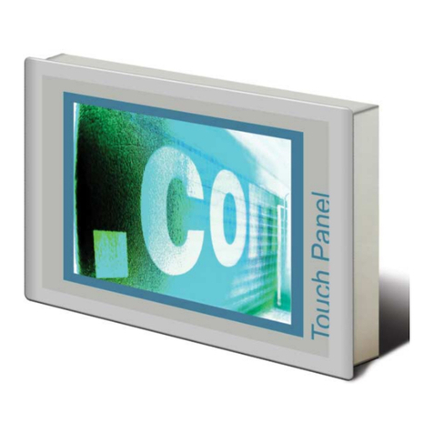
  9. Protech Systems SP-6267 User manual

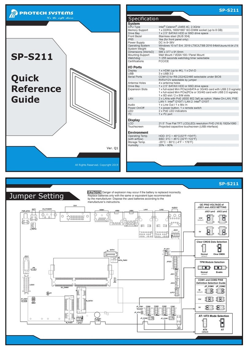
Protech Systems SP-6267 User manual

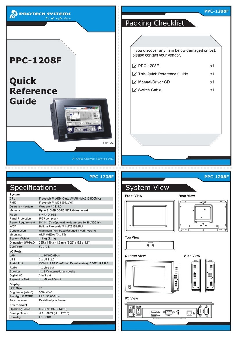
Ver. Q1
All Rights Reserved. Copyright 2018
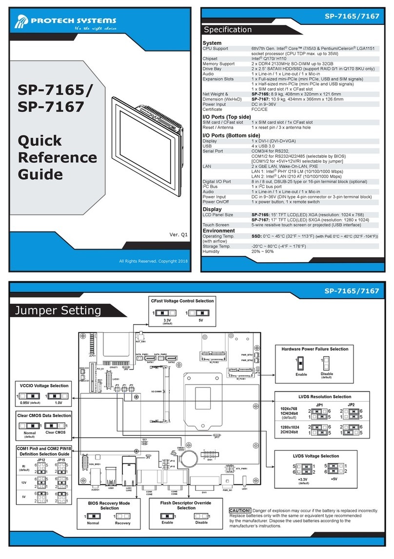
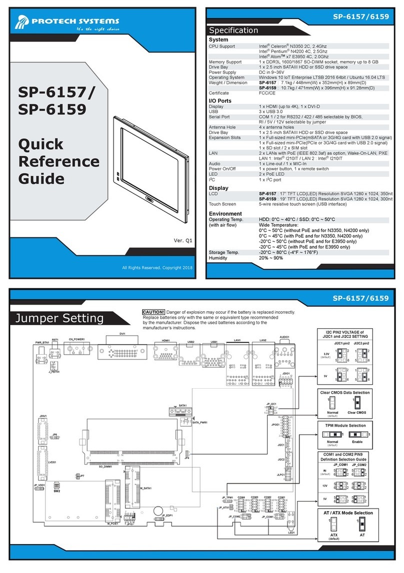
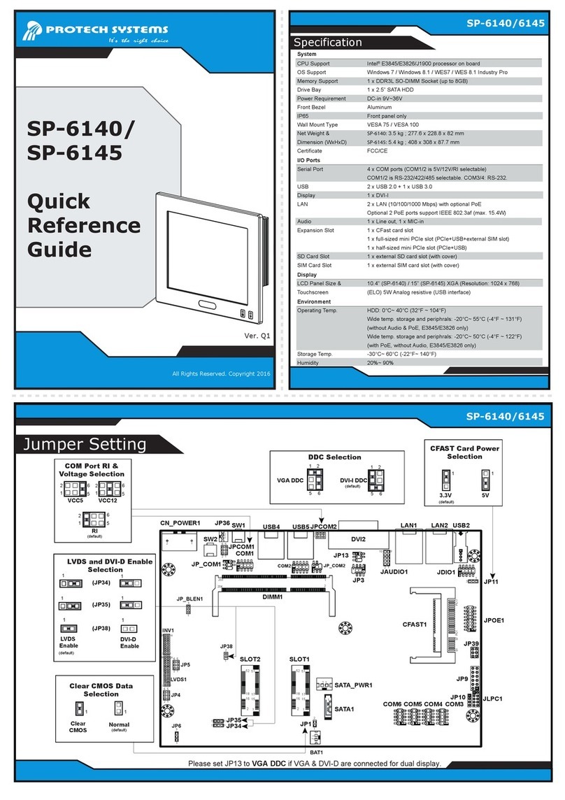
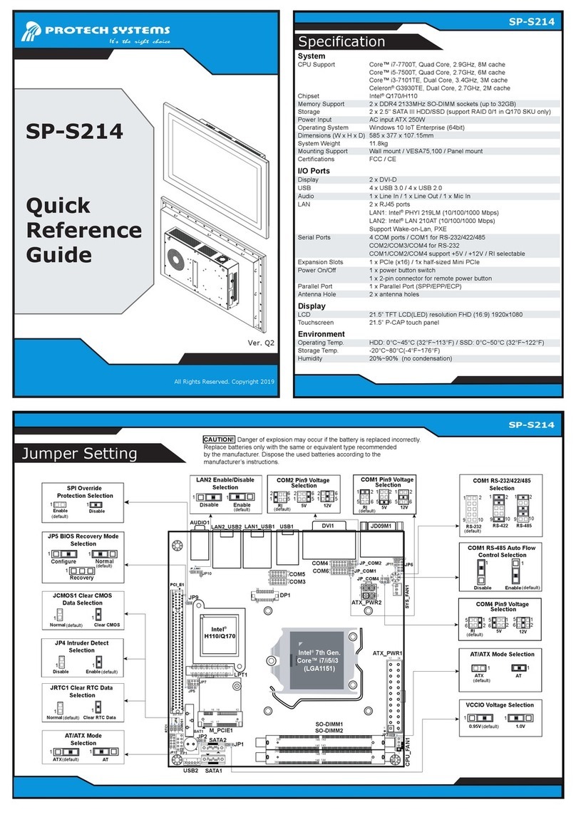
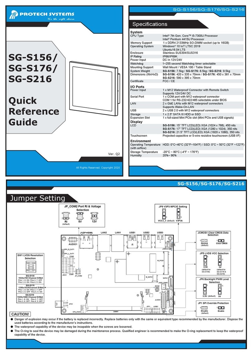
Specification
SP-6267/6269
SP-6267/6269
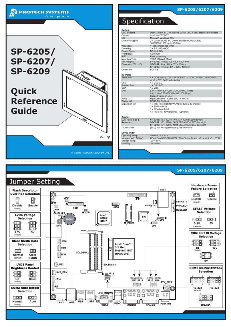
Jumper Setting
SP-6267/
SP-6269
Quick
Reference
Guide
System
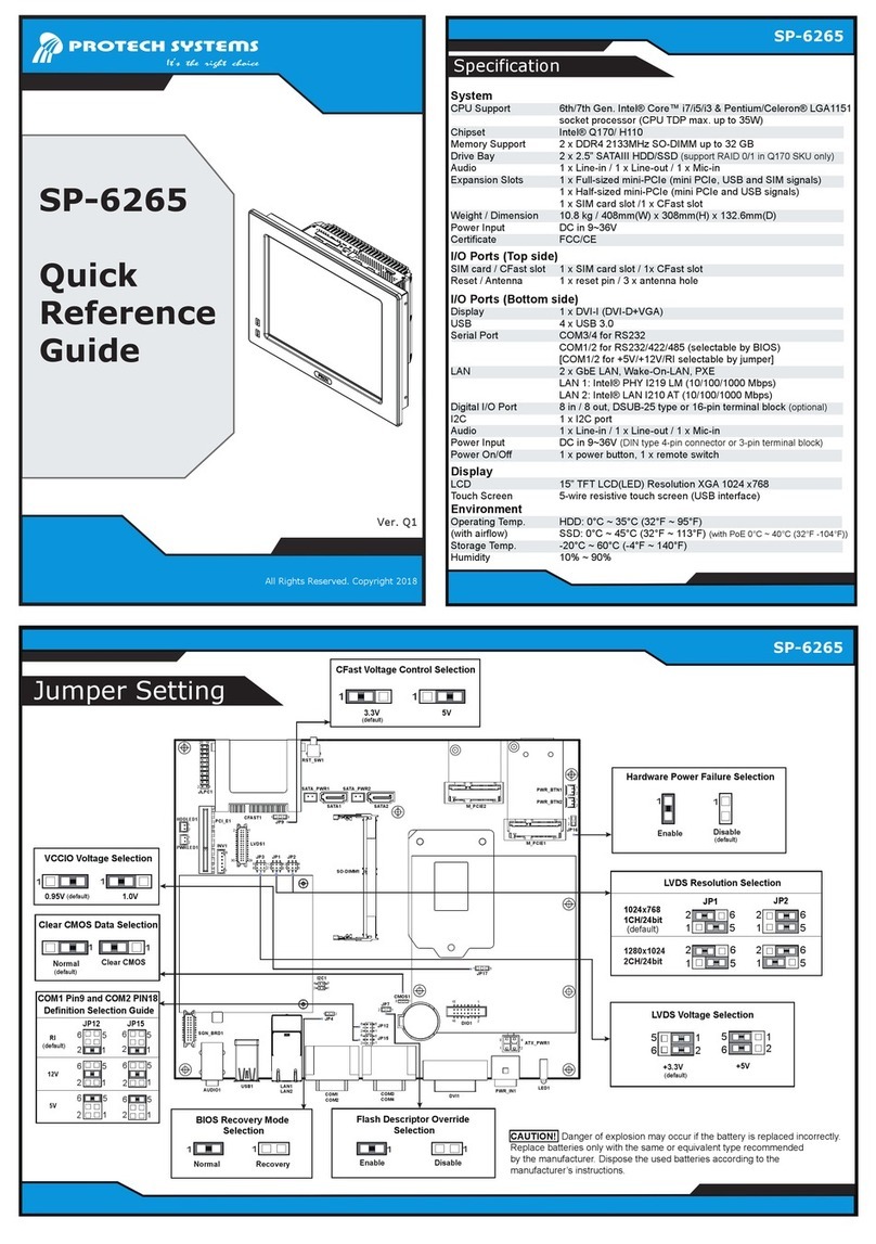
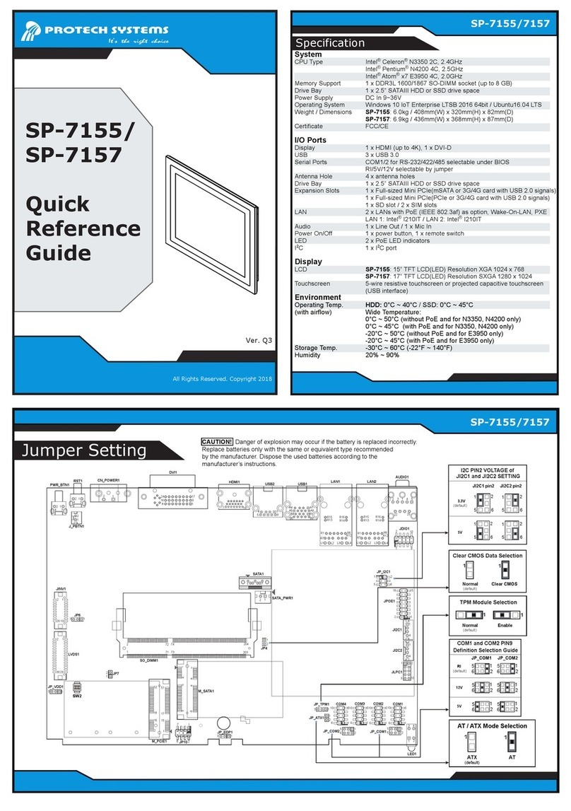
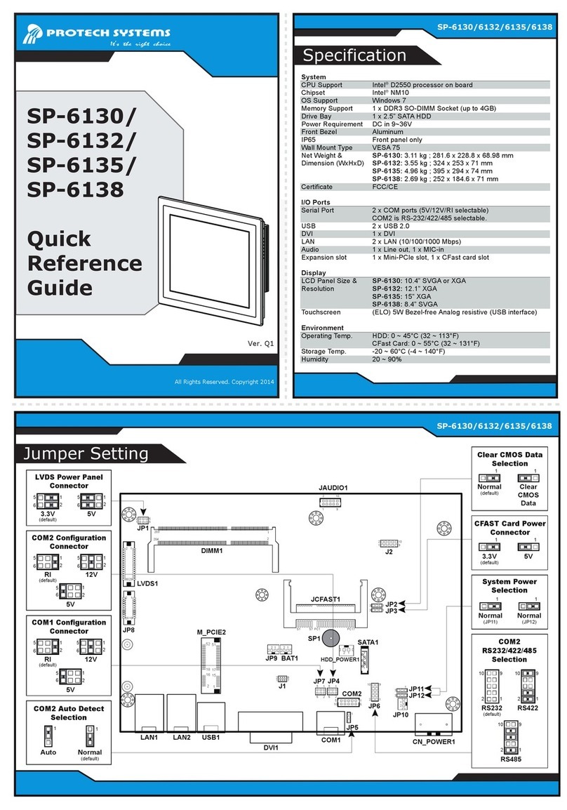
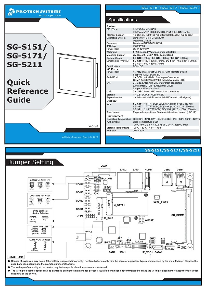
CPU Support 7th/6th Gen. Intel®Core™ i7/i5/i3 & Pentium/Celeron®
LGA1151 socket processor (CPU TDP max. up to 35W)
Chipset Intel®Q170/ H110
Memory Support 2 x DDR4 2133MHz SO-DIMM up to 32 GB
Drive Bay 2 x 2.5” SATA 3.0 SSD (support RAID 0/1 in Q170 SKU only)
Audio 1 x Line In / 1 x Line Out / 1 x Mic In
Expansion Slots 1 x Full-sized mini-PCIe (mini PCIe, USB and SIM signals)
1 x Half-sized mini-PCIe (mini PCIe and USB signals)
1 x SIM card slot /1 x CFast slot
Weight / Dimensions SP-6267: 10.5 kg / 448mm(W) x 352mm(H) x 128.6mm(D)
SP-6269: 11.5 kg / 471mm(W) x 396mm(H) x 130.9mm(D)
Power Input DC in 9~36V
Certificate FCC/CE
I/O Ports (Top side)
SIM card / CFast slot 1 x SIM card slot / 1x CFast slot
Reset / Antenna 1 x reset pin / 3 x antenna hole
I/O Ports (Bottom side)
Display
USB
Serial Ports
LAN
Digital I/O Port
I2C
Audio
Power Input
Power On/Off
Display
LCD
Touchscreen
Environment
Operating Temp.
(with airflow)
Storage Temp.
Humidity
1 x DVI-I (DVI-D+VGA)
4 x USB 3.0
COM3/4 for RS232
COM1/2 for RS232/422/485 (selectable by BIOS)
[COM1/2 for +5V/+12V/RI selectable by jumper]
2 x GbE LAN, Wake-On-LAN, PXE
LAN 1: Intel®PHY I219 LM (10/100/1000 Mbps)
LAN 2: Intel®LAN I210 AT(10/100/1000 Mbps)
8 in / 8 out, DSUB-25 type or 16-pin terminal block (optional)
1 x I2C port
1 x Line In / 1 x Line Out / 1 x Mic In
DC in 9~36V (DIN type 4-pin connector or 3-pin terminal block)
1 x power button, 1 x remote switch
SP-6267:17” TFT LCD(LED) Resolution SVGA 1280 x 1024, 350nit
SP-6269:19” TFT LCD(LED) Resolution SVGA 1280 x 1024, 350nit
5-wire resistive touch screen (USB interface)
SSD: 0°C ~ 45°C (32°F ~ 113°F) (without PoE)
0°C ~ 40°C (32°F -104°F) (with PoE)
-20°C ~ 60°C (-4°F ~ 140°F)
10% ~ 90%
1
CAUTION! Danger of explosion may occur if the battery is replaced incorrectly.
Replace batteries only with the same or equivalent type recommended
by the manufacturer. Dispose the used batteries according to the
manufacturer’s instructions.
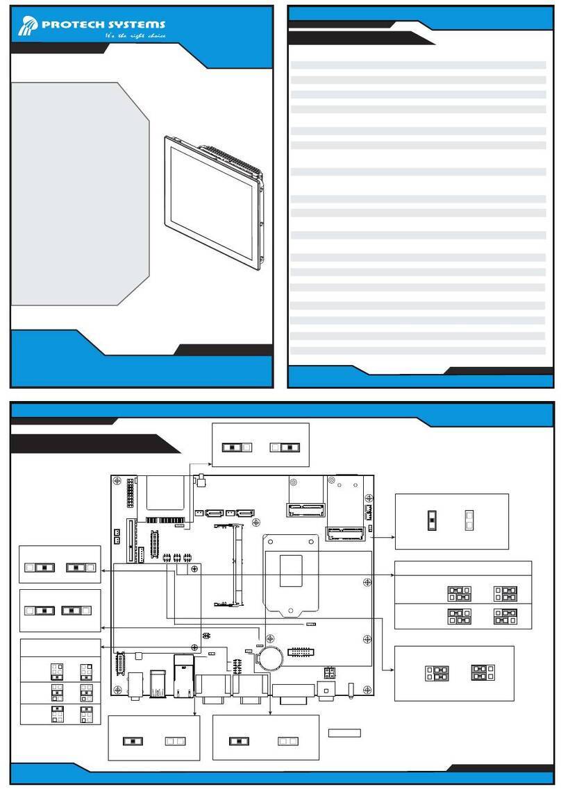
CFast Voltage Control Selection
3.3V 5V
(default)
1
1
Flash Descriptor Override
Selection
Disable
1
1
Enable
DVI1
COM3
COM4
COM1
COM2
BIOS Recovery Mode
Selection
Normal
1
Recovery
1
Hardware Power Failure Selection
Disable
(default)
Enable
1
1
JP4
56
1
2
1
5
2
6JP15
JP12
12
JP7 13
DIO1
115
216
1
3
2
4ATX_PWR1
1 3
JP17
LED1
PWR_IN1
LAN1USB1
AUDIO1
12
3
4
I2C1
1
2
JP16
M_PCIE1
PWR_BTN1
PWR_BTN2
SATA2
SATA_PWR2
SATA1
SATA_PWR1
RST_SW1
1 3
JP9
CFAST1
JLPC1
HDDLED1
PWRLED1
PCI_E1
SO-DIMM1
M_PCIE2
CMOS1
1
1
2
2
1
2
15
16
17
18 52
51
1
2
15
16
17
18
51
52
12
1920
1
1
2
2
LAN2
12
COM1 Pin9 and COM2 PIN18
Definition Selection Guide
JP15JP12
RI
12V
5V
5
1
6
2
2
5
1
6
2
2
5
1
6
2
5
1
6
2
5
1
6
2
2
5
1
6
2
2
(default)
VCCIO Voltage Selection
0.95V 1.0V
(default)
1
Clear CMOS Data Selection
Normal Clear CMOS
(default)
11
LVDS1
12
2930
INV1
1
6
1
2
5
6
JP1
1
2
6
5
JP2
5
6
1
JP3
2
1280x1024
2CH/24bit
5
6
1
2
5
6
1
2
LVDS Resolution Selection
1024x768
1CH/24bit
(default)
JP1
5
6
1
2
JP2
5
6
1
2
LVDS Voltage Selection
5
6
1
2
5
6
1
2
+3.3V
(default)
+5V
SGN_BRD1
All Rights Reserved. Copyright 2017
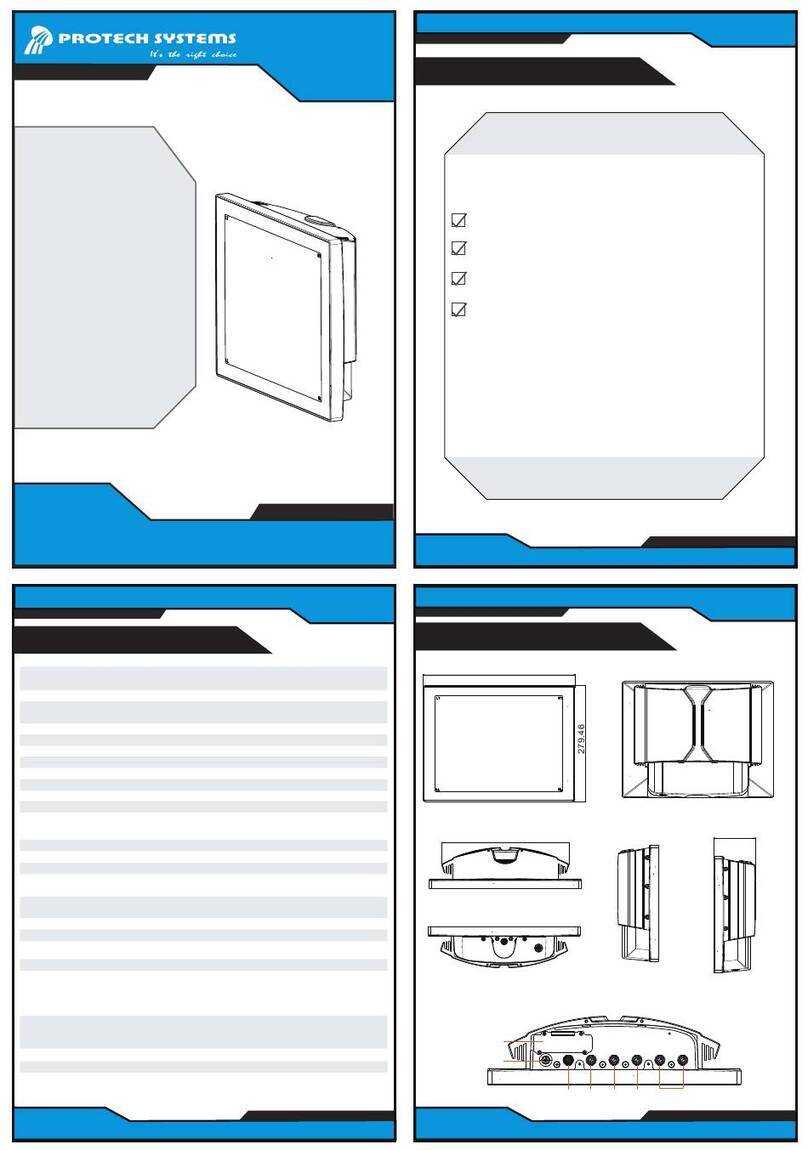
Rear View (SP-6269)
(Unit: mm)
The following messages are reminders for safety on how to protect your system from damages and to extend a long life of the system.
1. Check the Cable Voltage
• The range of operating voltage should be be within the range of 100V to 240V AC. Otherwise, the system may be damaged.
2. Environmental Conditions
• Place your SP-6267 / SP-6269 on a sturdy, level surface. Be sure to allow enough space to have easy access around the system.
• Avoid extremely hot or cold place to install the system.
• Avoid exposure to sunlight for a long period of time or in an airtight space.
• Avoid the system from any heating device or using SP-6267 / SP-6269 when it’s been left outdoors in a cold winter day.
• Bear in mind that the operating ambient temperature is from 0°C ~ 35°C for HDD & 0°C ~ 45°C for SSD.
• Avoid moving the system rapidly from a hot place to a cold place and vice versa because
condensation may come from inside of the system.
• Placing SP-6267 / SP-6269 in strong vigrations may cause hard disk failure.
• Don’t place the system close to any radio-active device in case of signal interference.
3. Handling
• Avoid putting heavy objects on top of the system.
• Don not turn the system upside down. This may cuase the floppy drive and hard drive to mal-function.
• If water or other liquid spills into this product, unplug the power cord immediately.
4. Good Care
• When the outside of the case is stained, remove the stain with a neutral washing agent with a dry cloth.
• Never use strong agents such as benzene and thinner to clean the system.
• If heavy stains are present, moisten a cloth with diluted neutral washing agent or with alcohol and then wipe thoroughly with a dry cloth.
• If dust has been accumulated on the outside, remove it by using a special made vacuum cleaner for computers.
CAUTION! Danger of explosion if battery is incorrectly replaced. Replace only with the same or equivalent type recommended by the
manufacturer. Dispose of used batteries according to the manufacturer’s instructions.
WARNING! Some internal parts of the system may have high electrical voltage. And therefore we strongly recommend that qualified engineers
can open and disassemble the system. Please handle LCD and Touchscreen with extra care as they are easily breakable.
Installing Panel Mount
Tighten the screws into the 12 mounting holes
(SP-6267) / 18 mounting holes (SP-6269) of the wall
fixture as shown to mount Panel PC onto the wall
securely. The panel mount installation is applicable for
both SP-6267 and SP-6269 Panel PCs.
1. Install the bracket.
2. Tighten the screw.
Step 1. Install the hooks into the mounting hole
on the four sides of SP-6267 & SP-6269
using 8 pieces M3x5mm screws.
SP-6267 & SP-6269
Step 2. Mount SP-6267 & SP-6269 Panel
PC equipped with 8 hooks onto
SP-6267 & SP-6269 SP-6267 & SP-6269
Step 3. The operation is the same as above.
Installing Hooks
Front View Rear View (SP-6267)
Right Side View
SP-6267 SP-6269
Wall Mount Cut-out Dimensions
Wall
Installing VESA Mount
M4 Nut
Hook
x 8 for SP-6267
Hook Accessories (option)
x 4 for SP-6267 & SP-6269
Mounting Brackets
M3x5mm screw
x 8 for SP-6267
M4x35mm screw
x 8 for SP-6267
x 8 for SP-6267
C.L.100(VESA)
System Overview
Bottom I/O View
SSD cable *2
M3 screw *6
Bottom Cover
SSD *2
M3 screw *4
SSD Bracket
SSD screw *8
DRAM
DRAM CPU
M3 Screw*6
HEATSINK TOP COVER
Installing 1st Memory and CPU
Installing 2nd Memory and SSD
Line Out
Remote
Switch
DIO
DC IN DVI-I
1
2
LAN
I2C
1
2
USB 3.0 MIC-in
Line In
COM3
COM4
COM1
COM2
POE ON
Power
Button
Remote
Switch
DVI-I
DIO
1
2I2C
LAN USB 3.0 MIC-in
Line Out
Line In
1
2
DC IN 9~36V
COM3
COM4
COM1
COM2
POE ON
Power
Button
448 (SP-6267)
471 (SP-6269)
352 (SP-6267)
396 (SP-6269)
C.L.100(VESA)
107C.L.100 (VESA)
112
C.L.100 (VESA)
SP-6267
Top View
404
260
128.6
42
10
39
230
308
22
130.9
44.3
48
230
360
18
10
374
364
SP-6267
Wall
421.5
410
138
325.5
314
106
4.7 Hole - 12X
Quick Setup
Wall
the wall firmly.
Safety Precaution
SP-6269
449
439
276
92
4.7 Hole - 18X
192
Wall
374
364
ANT
CFast Reset
ANT ANT
SIM Card
SP-6269 435
260
SIM Card
ANT
ANT
ANT
CFast Reset
This manual suits for next models

1

Other Protech Systems Touch Panel manuals

Protech Systems SP-7755 User manual

Protech Systems

Protech Systems SP-7755 User manual

Protech Systems SP-6565 User manual

Protech Systems

Protech Systems SP-6565 User manual

Protech Systems SP-7117 User manual

Protech Systems

Protech Systems SP-7117 User manual

Protech Systems SP-7155 User manual

Protech Systems

Protech Systems SP-7155 User manual

Protech Systems PPC-7400 User manual

Protech Systems

Protech Systems PPC-7400 User manual

Protech Systems PPC-7528F User manual

Protech Systems

Protech Systems PPC-7528F User manual

Protech Systems SP-7256 User manual

Protech Systems

Protech Systems SP-7256 User manual

Protech Systems SP-S214 User manual

Protech Systems

Protech Systems SP-S214 User manual

Protech Systems SP-6110 User manual

Protech Systems

Protech Systems SP-6110 User manual

Protech Systems SP-6140 User manual

Protech Systems

Protech Systems SP-6140 User manual

Protech Systems SP-7165 User manual

Protech Systems

Protech Systems SP-7165 User manual

Protech Systems SP-6558 User manual

Protech Systems

Protech Systems SP-6558 User manual

Protech Systems SP-6555 User manual

Protech Systems

Protech Systems SP-6555 User manual

Protech Systems SP-S211 User manual

Protech Systems

Protech Systems SP-S211 User manual

Protech Systems SG-S151 User manual

Protech Systems

Protech Systems SG-S151 User manual

Protech Systems SG-S156 User manual

Protech Systems

Protech Systems SG-S156 User manual

Protech Systems SP-6205 User manual

Protech Systems

Protech Systems SP-6205 User manual

Protech Systems SP-6157 User manual

Protech Systems

Protech Systems SP-6157 User manual

Protech Systems SP-6130 User manual

Protech Systems

Protech Systems SP-6130 User manual

Protech Systems SG-G151 User manual

Protech Systems

Protech Systems SG-G151 User manual

Protech Systems PPC-1208F User manual

Protech Systems

Protech Systems PPC-1208F User manual

Protech Systems SP-6265 User manual

Protech Systems

Protech Systems SP-6265 User manual

Protech Systems PPC-7365F User manual

Protech Systems

Protech Systems PPC-7365F User manual

Popular Touch Panel manuals by other brands

Systemline E50 installation guide

Systemline

Systemline E50 installation guide

AXIOMTEK PANEL1173-841 user manual

AXIOMTEK

AXIOMTEK PANEL1173-841 user manual

Boser BPC-5015 installation instructions

Boser

Boser BPC-5015 installation instructions

AURES TEOSWIDE 22i5 user manual

AURES

AURES TEOSWIDE 22i5 user manual

Russound UNO-TS2D instruction manual

Russound

Russound UNO-TS2D instruction manual

Winmate R15FA3S-PCC3-PoE user manual

Winmate

Winmate R15FA3S-PCC3-PoE user manual

Astraada AS47CN08 user manual

Astraada

Astraada AS47CN08 user manual

Wincomm WTP-8B66 Series user manual

Wincomm

Wincomm WTP-8B66 Series user manual

Kontron MediClient 23.8" user guide

Kontron

Kontron MediClient 23.8" user guide

Minebea CSD-709 Start guide

Minebea

Minebea CSD-709 Start guide

Stahl ORCA01E Series operating instructions

Stahl

Stahl ORCA01E Series operating instructions

Tru-Test JR 3000 quick start guide

Tru-Test

Tru-Test JR 3000 quick start guide

Aplex APC-3X17B user manual

Aplex

Aplex APC-3X17B user manual

Icop PMX-057T-5A user manual

Icop

Icop PMX-057T-5A user manual

Avalue Technology C Series Quick reference guide

Avalue Technology

Avalue Technology C Series Quick reference guide

Eaton XP-503 user manual

Eaton

Eaton XP-503 user manual

Qbic Luminen 10 quick start guide

Qbic

Qbic Luminen 10 quick start guide

AXIOMTEK GOT315W-521-PCT user manual

AXIOMTEK

AXIOMTEK GOT315W-521-PCT user manual

manuals.online logo
manuals.online logoBrands
  • About & Mission
  • Contact us
  • Privacy Policy
  • Terms and Conditions

Copyright 2025 Manuals.Online. All Rights Reserved.