RIKEN SEIKI SMP-30 Series User manual

COMPACTELE. HYDRAULICPUMP
SMP-30, 40 Series
INSTRUCTION MANUAL
RIKEN KIKI CO., LTD

-1--1-
Foreword
ThankyouverymuchforpurchasingthiselectricallypoweredpumpproducedbyRikenKikiLtd.
Thismanualexplainstheuseandsafetyfeaturesofthesemotorpoweredpumpsandcontains
informationvaluabletobothexperiencedandalsofirsttimeusersoftheseelectricallypowered
pumps.Thereforethecontentsofthismanualshouldbereadandfullyunderstoodbyall
personnelwhowillusethesepumps.Keepthismanualinasafeplacebutaccessiblefor
referenceduringoperation.
CautionsRegardingSafety
Properoperationandperiodicinspectionareabsolutelynecessarytoensuresafeusageof
thepump.Donotoperatethemicropumpuntilthesafetypointslistedinthismanualhave
beenreadandfullyunderstood.Themark
“WARNING”isusedtodenoteitemsthatmayleadtobodilyinjuryifsafetypointsare
notfollowed.
“CAUTION”isusedtodenoteitemsthatmayleadtodamageormalfunctionofthe
micropumpifsafetypointsarenotfollowed.BothWARNINGandCAUTIONsections
containimportantinformationthatmustbefollowed.Shouldthemicropumpmalfunction
duringoperation,removetheelectricalplugandcontactyoursalesorservicerepresentative.
(1)Donotusethesepumpswhereanoilleakwillcausedamagetoadjacentequipmentorthe
surroundingarea.Alsodonotusepumpsclosetoflammablematerialstominimizetheriskof
injuryandfire.
(2)Pumpswillnotgeneratepressureuntilthedischargeoutletplugisremoved.Thereforebefore
starting,removetheplugfromtheoutletportandreplacewithhighpressurehosesorcouplers.
(3)Themaximumoutputpressureofthesepumpsis70MPa.Forsafety,eachpumpisfactory
fittedwithahighpressuresafetyvalveadjustedto73MPa.Donotallowthesafetyvalvetobe
increasedalevelhigherthan73MPa.Wherethepumpisfittedwithapressureswitch,set
thisat70MPaorless.
(4)Whenusingthepumptopowerhydraulicequipmentwithaworkingpressureoflessthan70
MPa,eitherlowerthesettingofthehighpressuresafetyvalveoradjustthepressureswitchto
matchtheworkingpressureoftheequipment.Bewarnedfailuretolowersettingscouldresult
inequipmentdamage.Refertopage37“AdjustingtheHighPressureSafetyValve”forthe
procedureregardingpressureadjustment.
(5)Ensurepowerisswitchedoffbeforeconductingelectricallyrelatedmaintenanceorinspection.
(6)Releasingthepressuresuddenlyfromthejackingupcylinderorwirestandoccurstodropping
orbouncingoftheloads,andithappenstopersonalinjury.Thebasicpumpis“dump”type
andisnotdesignedtoholdpressureoncethemotorstops,avarietyofvalvesareavailable
fromRikentoprovidepressureholdwhenrequired.ContactRikenoryourlocalsalesagent
forinformationonsuitablevalvestoprovidepressureholdandreleasefunctions.
WARNINGS

-2-
(7)EnsurethattheOperationSwitchisturnedoffbeforeinsertingthepowercordplugintoa
powersourceotherwisethepumpwillstart,causingthecylinderpistontoextendandthe
pumptocreatepressure.
(8)Topreventelectricshock,ensurethepumpearthwireisconnectedtotheelectricalplugand
switch.
(9)AnymodificationtothesepumpswithouttheconsentofRikencouldcausedamageaswellas
compromisethesafetyoftheoperatoroftheseelectricpumps.ContactRikenbeforeany
modificationsarecarriedout.Rikenwillassumenoresponsibilityformodificationsperformed
withoutpermission.
(10)Thepumpreservoirisfittedwithanairvalvewhichallowsairtoreplaceoilasitisused.Ifthe
pumpisoperatedwiththeairvalveclosed,thefulltankcapacitywillnotbeavailablebutmore
dangerous,theinternalpressureofthereservoircouldrisewhenoilreturnscausingdamage
tooccurtothereservoir.
(11)Donotallowanamountofhydraulicoilgreaterthantheoiltankcapacity,toreturnintothe
reservoir.Ifanamountofoilexceedingthereservoircapacityisattemptedandtheairvalveis
open,oilwillleakoutoftheairvalve.However,iftheairvalveisclosed,theadditionaloil
capacitywillcauseapressurerisewithintheoiltankwhichcouldcausethetanktofracture
andamajoroilspilltooccur.
(12)Tightenthehexagoncapnutofthecoupler(S-1,2,5)byhandcompletelyuntiltheheadof
thenutisflushwiththelipofthehosecoupler.Cylinderswillnotoperatesmoothlyifagapis
leftasshowninthediagrambelow.Whenusingdoubleactingcylinders,shouldthepullor
retractsidecouplernotbecompletelyclosed,excessivepressurewillbegeneratedinthe
retractorpullsideofthecylinderjustbyanormalpressureonthepushcylinderside.This
willcausedamageeithertothecoupler,thecylinder,orthehighpressurehose,orallthree
andmayalsoresultinaseriousbodilyinjury.
(13)Doplacehandsorotherbodypartsnearareaswherehydraulicoilisbeingdispersedashigh
pressureoilmaypenetratetheskinandcauseseriousinjury.
(14)Ifoilenterstheeye,thoroughlyflushtheeyewithsterilewaterforatleast15minutesbefore
consultingadoctor.Also,ifoilcontactstheskin,washthoroughlywithwaterandsoap.
PullSide
PushSide
Gap
Good Not good
BagNut
BagNut

-3-
(15)Donotgripthehighpressurebyhandwhenpressureisbeingexerted.Ifthepressurehose
breakswhileitisbeinggrippedbyhand,highpressurehydraulicoilwillbesuddenly
dispersed,andseriousinjurysuchasaholebeingopenedinoneʼshandmayoccur.
(16)Thehighpressurehoseisaconsumableitem.Evenifthehoseexteriorappearstobein
goodcondition,itispossibleinternaldamagesuchaspinholeshaveoccurred.Riken
recommendperiodicreplacementbaseduponhowfrequentlyhoseshavebeenused
combinedwithspecificapplicationconditions.Thismightmeanreplacingthehoseevenifthe
lifespanhasnotfullyexpired.
(17)Carefullychecktheincreaseinoiltemperatureandmotorheatingwhenthepumpisused
continuously,andbesuretofollowthetimeregulationforeachpump.
CAUTIONS
(1)Usegeneral-purposeISOVG32oilwiththeelectricpump(RIKENPOWEROIL).
Phosphoester,waterglycol,andw/oemulsionoilscannotbeused.
Theelectricpumpwillmalfunctionduetodeteriorationofpackingandcorrosionofthe
equipment.ContactRikenwhenusingthesekindsofunapprovedoils.
(2)Donotusethehighpressuresafetyvalveasareliefvalve.Installaseparatereliefvalveifitis
necessarytoperformcontinuousrelief.
(3)Whenanairreleasevalve(SV-1000)isinstalledandairreleaseisperformed,hydraulicoilwill
comeoutofthedischargeholesoftheairreleasevalve.Useaclothorothersuitablematerial
topreventdispersionoftheoil.
(4)Wasteoilgeneratedbytheelectricpumpisclassifiedasan“IndustrialWasteProduct”.
Consultyourlocalregulatoryagenciesanddisposeoftheoilthroughalicensedindustrial
wastecollectionagencyorindustrialwasteprocessingagency.

-4-
TableofContents
1.O ver v i e w ............................................................................................................................... 5
2.Model Explanation..................................................................................................................... 5
3.Shared Specifications................................................................................................................ 6
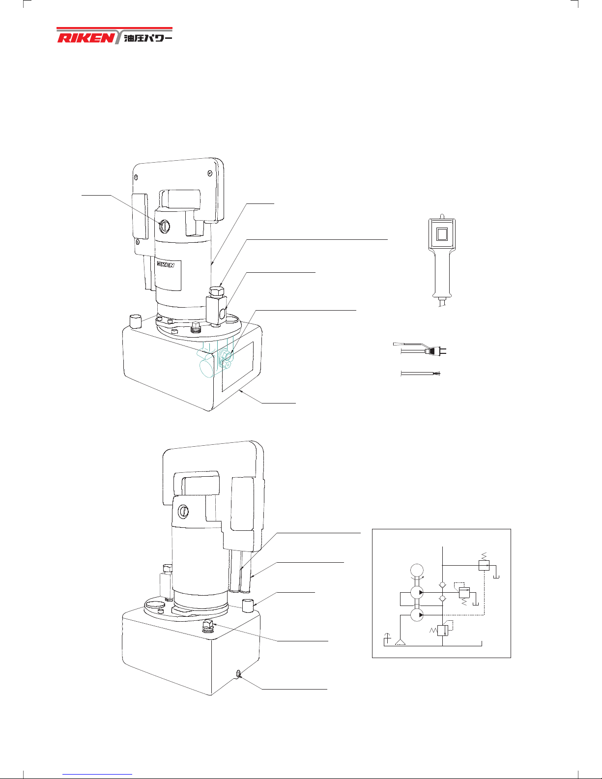
4.Explanation of Components ...................................................................................................... 7
5.Safety Cautions for Usage ...................................................................................................... 16
6.Fixed Installation Method ........................................................................................................ 18
7.Preparation Before Use........................................................................................................... 20
8.Preventive Maintenance.......................................................................................................... 21
(1) Inspection of Items Before Operation............................................................................... 21
(2) Inspection of Items During Operation............................................................................... 21
(3) Inspection Items After Operation ...................................................................................... 21
(4) Changing Hydraulic Oil .................................................................................................... 21
9.Explanation of Pressure Switch............................................................................................... 22
10.Operating Method.................................................................................................................... 23
(1) SMP-30NV、SMP-40NV ............................................................................ 23
(2) SMP-30B、SMP-40B ................................................................................... 23
(3) SMP-30AR、SMP-40AR ............................................................................ 24
(4) SMP-30SK、SMP-40SK ............................................................................ 25
(5) SMP-30BR、SMP-40BR ............................................................................ 26
(6) SMP-30NE、SMP-40NE ............................................................................ 27
(7) SMP-30RK、SMP-40RK ............................................................................ 28
(8) SMP-30C、SMP-40C ................................................................................... 29
(9) SMP-30DCB、SMP-40DCB ..................................................................... 30
(10) SMP-30DVH、SMP-40DVH ..................................................................... 31
(11) SMP-30CR、SMP-40CR ............................................................................ 32
(12) SMP-30SW、SMP-40SW ............................................................................ 33
(13) SMP-30SP、SMP-40SP ............................................................................ 34
(14) SMP-30SL、SMP-40SL ............................................................................ 35
11.Adjusting the High Pressure Safety Valve ............................................................................... 36
12.COMMON FAULTS AND SOLUTIONS ................................................................................... 37
13.Internal Structure Diagram ...................................................................................................... 38
14.Electrical Wiring, Terminal Connection List ............................................................................. 44
15.Handling the High Pressure Hose........................................................................................... 45

-5-
1. Overview
(1) Thispumpisanelectricpumpforoperatingahydraulicactuator(cylinder,etc.).Thepump
featuresautomaticchangeoverbetweenhighpressureandlowpressure.Boththehigh
pressureandlowpressurepumpsinitiallyoperatesimultaneously.Oncethecircuit
pressurereaches1.5MPa,thelowpressuresafetyvalveactivatesandalloilflowfromthe
lowpressurepumpisthenreturnedtothetankviathelowpressuresafetyvalve.Fromthis
pressure(1.5MPa)onlyflowfromthehighpressurepumpproceedstothecylinder.
(2) Thepumpisnotdesignedforuseinareassubjecttowateringressorwhereitislikely
tobeexposedtoprecipitationorotherinclementweatherconditions.
(3) Useinareaswherethesurroundingtemperatureis0to40degreesCelsius.
(4) HydraulicequipmentusedwiththispumpshouldbeproductsmanufacturedbyRiken.
(5) Useonlywithahighpressurehose,orhighpressurepipeandconnectorsthathavea
maximumworkingpressureof70MPa.
(6) Donotuseinareaswhereseveredamagemayoccurshouldhydraulicoilleakor
escape.Specifically,donotusenearflammablematerialsduetotheriskofinjury
andfire.
(7) Thispumpisnotsparkresistantandthereforeshouldnotbeusedinhazardousareas.
(8) Donotmodifythispumpforusageotherthantheintendedusage.
2. ModelExplanation
SMP - 30 1 2 NV
BasicType
3WayValveManualOperationType
AutomaticReturnType
IntermediateStopType
3WayValveManualOperationwithRelief
Non-InertiaType
Return-HoldType
NV
B
AR
SK
BR
NE
RK
:
:
:
:
:
:
:
ForSingle-Acting
Cylinder
4WayValveManualOperationType
WithAutomaticFallingPreventionValve
PressureMaintenanceType
4WayValveManualOperationwithRelief
CenterBypassType
PPortBlockType
ShuttleValveLoadingType
C
DCB
DVH
CR
SW
SP
SL
:
:
:
:
:
:
:
ForDouble-Acting
Cylinder
CompactElectricHydraulicPump
30
40
Series
1:100V
2:200V
3:230V
MotorVoltage
2:2L
4:4.5L
6:6.5L
TankOil
Amount

-6-
3. SharedSpecifications
・SMP−30**
MaximumUsagePressure
DischargeAmount
Motor
PermittedVoltageFluctuation
SurroundingTemperature
OilTankCapacity
UsableOilAmount
HydraulicOilUsed
HighPressureSide 70MPa
LowPressureSide 1.5MPa
HighPressureSide 0.2L/min
LowPressureSide 2.0L/min
ClosedType,TypeEInsulation
RatedOutput250W
RatedOperationTime5minutes
Maximumcurrent(A)8.0at100V
4.0at200V
4.0at230V
RatedVoltage ±5%
0to40degreesCelsius
2.0L4.5L6.5L
1.8L4.0L6.0L
General-PurposeISOVG32Oil(HazardousMaterial:Group4,
PetroleumCategory4) (RIKENPOWEROIL)
MaximumUsagePressure
DischargeAmount
Motor
PermittedVoltageFluctuation
SurroundingTemperature
OilTankCapacity
UsableOilAmount
HydraulicOilUsed
HighPressureSide 70MPa
LowPressureSide 1.5MPa
HighPressureSide 0.4L/min
LowPressureSide 3.0L/min
ClosedType,TypeEInsulation
RatedOutput450W
RatedOperationTime5minutes
Maximumcurrent(A)12.0at100V
6.0at200V
5.2at230V
RatedVoltage ±5%
0to40degreesCelsius
2.0L4.5L6.5L
1.8L4.0L6.0L
General-PurposeISOVG32Oil(HazardousMaterial:Group4,
PetroleumCategory4) (RIKENPOWEROIL)
・SMP−40**
Carefullychecktheincreaseinoiltemperatureandmotorheatingwhenthepumpis
usedcontinuously,andbesuretofollowthetimeregulationforeachpump.

-7-
4. ExplanationofComponents
(1)SMP−30NV、SMP−40NV
OFF
ON
Brush Motor
PressureGaugeAttachmentOpening
DischargeOutlet
(G1/2)
(Rc3/8)
HighPressureSafetyValve
OilTank
OperationSwitch
(SW-4A)
ShapeofPowerCordTip
100V
200V・230V
Opening
Airvalve
DrainOilOutlet
(Rc1/4)
PowerCord
IntakeOpening
OperationCordIntake
Opening
ReturnInlet
(Rc3/8)
HydraulicCircuitDiagram
H
L
M
Weight:14.5kg
(WhenUsing2Ltank)

-8-
OilTank
Reservoirforthestorageofhydraulicoil.
Motor
Motorfordrivingthepump.
OperationSwitch(SW-4A)
Manualswitchforstartingandstoppingthemotor.
Lengthofthecordis3meters.
PowerCord
Lengthofthecordis3meters.
100Vspecificationsisforinsertionplug(2P12A125Vwithearthclip).
200Vand230Vspecificationsareforsingleline(noplug).
(AnearthlineisindicatedE)
HighPressureSafetyValve
Avalvetolimitthemaximumpressureinordertopreventdamagetothemachineandpiping.
Setto73MPaatthetimeofshipping.
AirValve
Controlsadmissionandemissionofairinsidetheoiltanktocreateasmoothflowofhydraulicoil.
DischargeOilOutlet
Aportforthedischargeofhydraulicoilinsidetheoiltank.
ReturnInlet
Aportusedwhenreturninghydraulicoilfromtheexteriortotheoiltank.
DischargeOutlet
Aportfordischarginghydraulicoiltotheexterior.Diameteroftheportisequaltothetaper
screwRc3/8forusewithpiping.

-9-
(2)SMP−30B、SMP−40B
(3)SMP−30AR、SMP−40AR
HighPressureSwitch(SPS-7A)
Pressurecanbevariablyadjustedfrom10to70MPa.
Themotorstopswhenpressurerisestothesetpressurelevel.
DirectionControlValve(SMV-33)
A3-wayvalvethatcontrolstheflowofhydraulicoilbymanualoperation.
HighPressureSwitch(SPS-7A)
Pressurecanbevariablyadjustedfrom10to70MPa.
Themotorstopswhenpressurerisestothesetpressurelevel.
ShapeofPowerCordTip
100V
200V・230V
OperationSwitch
(SW-4A)
OFF
ON
PressureGaugeAttachmentOpening
(G1/2)
DirectionControlValve
(SMV-33)
(Rc3/8)
DischargeOutlet
PressureSwitch
(SPS-7A)
Weight:14.5kg
(WhenUsing2Ltank)
HydraulicCircuitDiagram
H
L
M
DischargeOutlet
(Rc3/8)
(G1/2)
PressureGaugeAttachmentOpening
PressureSwitch
(SPS-7A)
OperationSwitch
(SW-4A)
ON
OFF
ShapeofPowerCordTip
100V
200V・230V
HydraulicCircuitDiagram
H
L
M
Weight:14.5kg
(WhenUsing2Ltank)

-10-
(4)SMP−30SK、SMP−40SK
(5)SMP−30BR、SMP−40BR
OperationSwitch(SW-4S)
Amanualswitchcontainingacrimpswitchforstartingandstoppingthemotorandapush
buttonswitchforreturning.
DirectionControlValve(SSL-2B)
Anelectromagneticvalveforopeningandclosingthereliefvalve.
DirectionControlValve(SMV-33)
A3-wayvalvethatcontrolstheflowofhydraulicoilbymanualoperation.
ExternalReliefValve(KRV-34)
Whenthepressureofthecircuitreachesthevaluesetforthevalve,thisvalvethat
maintainstheinternalpressureofthecircuitatthesetlevelbyreleasingaportion
orallofthehydraulicoiltothereturnside.
OperationSwitch
(SW-4A)
ON
OFF
ShapeofPowerCordTip
100V
200V・230V
DischargeOutlet
(Rc3/8)
(SMV-33)
DirectionControlValve
PressureGaugeAttachmentOpening
(G1/2)
(KRV-34)
ExternalReliefValve
(SSL-2B)
DirectionControlValve
(Rc3/8)
DischargeOutlet
(G1/2)
PressureGaugeAttachmentOpening
(SPS-7A)
PressureSwitch
ShapeofPowerCordTip
100V
200V・230V
OperationSwitch
(SW-4S)
ON
OFF
RETURN
HydraulicCircuitDiagram
H
L
M
Weight:14.5kg
(WhenUsing2Ltank)
Weight:16kg
(WhenUsing2Ltank)
HydraulicCircuitDiagram
H
L
M

-11-
(6)SMP−30NE、SMP−40NE
(7)SMP−30RK、SMP−40RK
OperationSwitch(SW-4WP)
Amanualswitchforstartingandstoppingthemotorandoperatingthedirectioncontrolvalve.
DirectionControlValve(KD-2C)2Places
A3-way,3-positionvalvethatcontrolsthedirectionofflowofhydraulicoilbyusinga
combinationof2solenoidvalves.
HighPressureSwitch(SPS-7A)
Pressurecanbevariablyadjustedfrom10to70MPa.
Themotorstopswhenpressurerisestothesetpressurelevel.
DirectionControlValve(KD-2C)
Ashut-offvalvethatusesolenoidoperationtocontrolthedirectionofflowof
hydraulicoil.
ShapeofPowerCordTip
100V
200V・230V
ShapeofPowerCordTip
100V
200V・230V
OperationSwitch
(SW-4WP)
PUSH
PULL
OperationSwitch
(SW-4WP)
PUSH
PULL
DischargeOutlet
(Rc3/8)
(G1/2)
PressureGaugeAttachmentOpening
(KD-2C)
DirectionControlValve
(SPS-7A)
PressureSwitch
(G1/2)
PressureGaugeAttachmentOpening
(Rc3/8)
DischargeOutlet
(KD-2C)
DirectionControlValve
(SPS-7A)
PressureSwitch
HydraulicCircuitDiagram
Weight:16.5kg
(WhenUsing2Ltank)
A
H
L
M
HydraulicCircuitDiagram
Weight:19kg
(WhenUsing2Ltank)
H
L
M
A

-12-
(8)SMP−30C、SMP−40C
(9)SMP−30DCB、SMP−40DCB
HighPressureSwitch(SPS-7A)
Pressurecanbevariablyadjustedfrom10to70MPa.
Themotorstopswhenpressurerisestothesetpressurelevel.
DirectionControlValve(SMV-43)
Amanual4-way,3-positionvalvethatcontrolsthedirectionofflowofhydraulicoil.
HighPressureSwitch(SPS-7A)
Pressurecanbevariablyadjustedfrom10to70MPa.
Themotorstopswhenpressurerisestothesetpressurelevel.
DirectionControlValve(SCB-43B)
Amanual4-way,3-positionvalvethatcontrolsthedirectionofflowofhydraulicoil.
Containsbothabuilt-inpilotcheckvalveandabuilt-inexternalpilot-typecounterbalance
valveinportB.
ShapeofPowerCordTip
100V
200V・230V
ShapeofPowerCordTip
100V
200V・230V
(Rc3/8)
DischargeOutlet
(SMV-43)
DirectionControlValve
(G1/2)
PressureGaugeAttachmentOpening
(SPS-7A)
PressureSwitch
PortA
PortB
(G1/2)
PressureGaugeAttachmentOpening
DirectionControlValve
(SCB-43B)
PortA
DischargeOutlet
(Rc3/8)
PortB
(SPS-7A)
PressureSwitch
HydraulicCircuitDiagram
Weight:15.5kg
(WhenUsing2Ltank)
H
L
M
BA
HydraulicCircuitDiagram
Weight:18.5kg
(WhenUsing2Ltank)
H
L
M
BA
OperationSwitch
(SW-4A)
ON
OFF
OperationSwitch
(SW-4A)
ON
OFF

-13-
(10)SMP−30DVH、SMP−40DVH
(11)SMP−30CR、SMP−40CR
HighPressureSwitch(SPS-7A)
Pressurecanbevariablyadjustedfrom10to70MPa.
Themotorstopswhenpressurerisestothesetpressurelevel.
DirectionControlValve(SMVH-43)
Amanual4-way,3-positionvalvethatcontrolsthedirectionofflowofhydraulicoil.
AcheckvalveisbuiltinsothatthepressureofportAandportBdoesnotfallwhen
replacingtheleverofthedirectioncontrolvalve(middleposition).
DirectionControlValve(SMV-43)
Amanual4-way,3-positionvalvethatcontrolsthedirectionofflowofhydraulicoil.
ExternalReliefValve
Whenthepressureofthecircuitreachesthevaluesetforthevalve,theinternalpressureof
thecircuitismaintainedatthesetlevelbyreleasingaportionorallofthehydraulicoiltothe
returnside.
PortA
DischargeOutlet
(Rc3/8)
PortB
(SMVH-43)
DirectionControlValve
(G1/2)
PressureGaugeAttachmentOpening
(SPS-7A)
PressureSwitch
PortA
DischargeOutlet
(Rc3/8)
PortB
ExternalReliefValve
(KRV-34)
(SMV-43)
DirectionControlValve
(G1/2)
PressureGaugeAttachmentOpening
OperationSwitch
(SW-4A)
ON
OFF
ShapeofPowerCordTip
100V
200V・230V
OperationSwitch
(SW-4A)
ON
OFF
ShapeofPowerCordTip
100V
200V・230V
HydraulicCircuitDiagram
Weight:17kg
(WhenUsing2Ltank)
H
L
M
BA
Weight:17kg
(WhenUsing2Ltank)
HydraulicCircuitDiagram
H
L
M
A B

-14-
(12)SMP−30SW、SMP−40SW
(13)SMP−30SP、SMP−40SP
HighPressureSwitch(SPS-7A)
Pressurecanbevariablyadjustedfrom10to70MPa.
Themotorstopswhenpressurerisestothesetpressurelevel.
DirectionControlValve:(KD-2S)1Place,(KD-3S,withcheckvalve)2Places
A4-way,3-positionvalvethatcontrolsthedirectionofflowofhydraulicoilbyusinga
combinationof3solenoidvalves.
HighPressureSwitch(SPS-7A)
Pressurecanbevariablyadjustedfrom10to70MPa.
Themotorstopswhenpressurerisestothesetpressurelevel.
DirectionControlValve(KD-3C)2Places
Amanual4-way,3-positionvalvethatcontrolsthedirectionofflowofhydraulicoilbyusing
acombinationof2solenoidvalves.
ShapeofPowerCordTip
100V
200V・230V
OperationSwitch
(SW-4WP)
PUSH
PULL
ShapeofPowerCordTip
100V
200V・230V
OperationSwitch
(SW-4WP)
PUSH
PULL
(withcheck)
KD-3S
(Rc3/8)
PortA
DischargeOutlet
PortB
DirectionControlValve
(KD-2S)
(G1/2)
PressureGaugeAttachmentOpening
(SPS-7A)
PressureSwitch
(Rc3/8)
DischargeOutlet
PortA
PortB
(G1/2)
PressureGaugeAttachmentOpening
DirectionControlValve
(KD-3C)
(SPS-7A)
PressureSwitch
Weight:19kg
(WhenUsing2Ltank)
HydraulicCircuitDiagram
H
L
M
B
A
Weight:20.5kg
(WhenUsing2Ltank)
HydraulicCircuitDiagram
H
L
M
B
A

-15-
(14)SMP−30SL、SMP−40SL
HighPressureSwitch(SPS-7A)
Pressurecanbevariablyadjustedfrom10to70MPa.
Themotorstopswhenpressurerisestothesetpressurelevel.
DirectionControlValve(KD-3C)1Place
Composesa4-way,2-positionvalvewhenusedtogetherwiththeincludedvalveplate.
(Nameof4-way,2-locationvalve:KSLV-34)
ShapeofPowerCordTip
100V
200V・230V
OperationSwitch
(SW-4WP)
PUSH
PULL
DischargeOutlet
(Rc3/8)
PortA
PortB
(G1/2)
PressureGaugeAttachmentOpening
DirectionControlValve
(KD-3C)
(SPS-7A)
PressureSwitch
Weight:18.5kg
(WhenUsing2Ltank)
HydraulicCircuitDiagram
H
L
M
A
B

-16-
5. SafetyCautionsforUsage
Pumpswillnotgeneratepressureuntilthedischargeoutletplugisremoved.
Thereforebeforestarting,removetheplugfromtheoutletportandreplacewithhighpressure
hosesorcouplers.
Themaximumoutputpressureofthesepumpsis70MPa.
Forsafety,eachpumpisfactoryfittedwithahighpressuresafetyvalvewhichfunctionsasasafety
deviceandisadjustedtothemaximumoperatingpressureatthetimeofshipping.
Donotallowthesafetyvalvetobeadjustedtoalevelhigherthanthemaximumoperatingpressure.
Also,adjustthepressureswitchto70MPaorless.
Whenusinghydraulicequipmentwithamaximumworkingpressureofless
than70MPa,eitherlowerthesettingsofthehighpressuresafetyvalveoradjustthepressure
switchtoequaltheworkingpressureoftheattachedequipment.Bewarnedfailuretolower
pressuresettingscouldresultinequipmentdamage.Refertopage37“Adjustingthe
HighPressureSafetyValve”fortheprocedureregardingpressureadjustment.
Ensurepowerisoffbeforeconductingelectricallyrelatedmaintenanceor
inspection.
AnymodificationtothesepumpswithouttheconsentofRikencouldcause
damageaswellascompromisethesafetyoftheoperator.ContactRikenbeforeanymodification
arecarriedout.Rikenwillassumenoresponsibilityformodificationsperformedwithoutthe
consentofRiken.
Thepumpreservoirisfittedwithanairvalvewhichallowsairto
replace.Theoilasitisused.Ifthepumpisoperatedwiththeairvalveclosed,
thefulltankcapacitywillnotbeavailablebutmoredangerous,theinternal
pressureinthereservoircouldrisewhenoilreturns,causingdamagetooccur
tothereservoir.
Donotallowanamountofoilgreaterthantheoiltankcapacitytoreturn
intothereservoir.Iftheairvalveisopen,oilwillspilloutoftheoilbleedholeandanoilspillage
willoccurbutiftheairvalveisclosed,theextraoilcapacitywillcauseapressurerisewithinthe
reservoirwhichcouldcausethetanktofractureandamajoroilspilltooccur.
Thebasicpumpisa“dump”typeandwillnot“hold”pressureorload,once
themotorstops.Releasingthepressuresuddenlyfromthejackinguporwirestandoccursto
droppingorbouncingoftheloads,andithappenstopersonalinjury.Avarietyofvalvesare
availablefromRikentoprovidepressure(load)holdingwhenrequired.ContactRikenoryourlocal
salesagentforsuitablevalvestoprovideholdandreleasefunctions.
WARNING
WARNING
WARNING
WARNING
WARNING
WARNING
WARNING
WARNING
開
閉
CLOSE
OPEN

-17-
Carefullychecktheincreaseinoiltemperatureandmotorheatingwhenthepump
isusedcontinuously,andbesuretofollowthetimeregulationforeachpump.
Usegeneral-purposeISOVG32oilwiththeelectricpump(forexample,
RIKENPOWEROIL).Phosphoester,waterglycol,andw/oemulsionoilscannotbeused.
Theelectricpumpwillmalfunctionduetodeteriorationofpackingandcorrosionoftheequipment.
ContactRikenshoulditbenecessarytousethesetypesofunapprovedoils.
Donotusethehighpressuresafetyvalveasareliefvalve.Installaseparate
reliefvalveifitisnecessarytoperformcontinuouspressurereliefoperation.
Useoilthatisbetween5°and60°Celsius.
Useofoilthatexceeds60°Celsiuswillshortenthelifespanofthemicropumpandleadto
malfunction.
Themostprevalentreasonforpumpmalfunctionisinfiltrationofdirtandother
foreignobjects.Thepumpandotherauxiliaryequipmentshouldbekeptcleantopreventthe
infiltrationofsuchforeignobjects.
Hydraulicoilshouldbechangedatleastonceayear.
WARNING
CAUTION
CAUTION
CAUTION
CAUTION
CAUTION

-18-
6. FixedInstallationMethod
(1)Installthepumpinalevelandsafelocation.
(a)Utilizingusingthescrewholesonthebottomoftheoiltank.
(b)Removetherubberfromthelegs.
(c)Removetheadhesivefromthescrewarea.
(2) Ensurethatthepowervoltagematchesthevoltageofthemotor.
(3) :EnsurethattheOperationSwitchisturned“off”beforeinsertingtheplug
ofthepowercord,otherwisewhentheOperationSwitchisturnedon,the
pistonofthecylindermayextendandpressuremaybeexerted.
(4) :Topreventelectricshock,ensurethatearthwireisconnectedintotheplug.
(5)ConnectiontotheCylinder
Connectthepumpandthecylinderusingahighpressurehoseorahighpressurepipe.
(A)WhenConnectingWithaHighPressureHose
Usethehighpressurehosebydirectlyscrewingitintothenormalpumpsideandusing
acouplertoconnectittothecylinderside.Ensurethatthetaperscrewareabeforefor
thepipingofthehighpressurehosehasbeenwrappedwithatapesealbeforescrewing
itin.
(B)WhenConnectingWithaHighPressurePipe
Refertopagesforsteelpipingorwedgeconnectorsinthegeneralcatalog,
orrequestaninstructionmanualforwedgeconnectorsfromasalesoffice.
Or,attachanairreleasevalvetothetipofthepipe.
4-M6(depth9)
Rubberforlegs
160
130
WARNING
WARNING
<*MethodforWrappingtheTapeSeal>
Leave1to2threadsexposedatthetipofthescrewforthemetal
fixture(R3/8)ononesideofthehighpressurehose.Wraptape
around1or2timesintheoppositedirectionofthescrewing
direction(counter-clockwise).
Screwtorqueis80to100Nm.
Ensurethatnotdirtorforeignobjectsareadheredtothecoupler
whenconnecting.
Wrappingdirection
HoseScrewingdirection
1or2threads

-19-
PullSide
PushSide
Gap
Good Not good
BagNut
BagNut
:WhenusingtheROC-13Seriesone-touchcoupler,aligntheringgroove
areaoftheROC-13Handwiththepositionofthenotch.Then,withtheringinapulled
backposition,pushuntilcontactismadewiththeROC-13Rcouplerandthenrelease
thering.Thecouplerwillconnectafterautomaticallylocking.Finally,completethe
connectionbyturningtheringtomovethepositionofthenotchandthegroovearea.
Also,ensurethatconnectionhasbeenperformedproperlybypullingtheROC-13H
couplerforwardandcheckingthatitdoesnotcomeloose.Whenusingdoubleacting
cylinders,shouldthepullorretractsidecouplerbenotcompletelyclosed,excessive
pressurewillbegeneratedintheretractorpullsideofthecylinderbyanormal
pressureonthepushcylinderside.Thiswillcausedamageeithertothecoupler,
thecylinder,orthehighpressurehose,orallthreeandmayalsoresultinaserious
bodilyinjury
Ring
Groovearea
Notch
ROC-13H ROC-13R
:Tightenthehexagoncapnutofthecoupler(S-1,2,5)byhandcompletely
untilthereisnogapbetweenthemaleandthefemalecouplersandtheedgeofthe
hexagonnutisflushwiththefaceofthemalecoupler.Thecylinderwillnotoperate
smoothlyifagapexistsasshowninthediagrambelow.Whenusingdoubleacting
cylinders,shouldthepullorretractsidecouplerbenotcompletelyclosed,excessive
pressurewillbegeneratedintheretractorpullsideofthecylinderbyanormalpressure
onthepushcylinderside.Thiswillcausedamageeithertothecoupler,thecylinder,
orthehighpressurehose,orallthreeandmayalsoresultinaseriousbodilyinjury.
WARNING
WARNING
This manual suits for next models
1
Table of contents
Popular Water Pump manuals by other brands

DAB PUMPS
DAB PUMPS ESYBOX DIVER 55/120 Instruction for installation and maintenance

EXTOL PREMIUM
EXTOL PREMIUM 8895150 user manual

Metabo
Metabo Elektra Beckum P 3300 K operating instructions

Magnum
Magnum MTP6000S3 operating manual

ALL PRIME
ALL PRIME S Series Installation, operation & maintenance manual

Meec tools
Meec tools 731107 operating instructions

Finish Thompson
Finish Thompson SF Series Operations & parts manual

Masdaf
Masdaf HEXA Series operating manual

Polygroup
Polygroup SUMMER WAVES SKIMMERPLUS SFS350 owner's manual

PFT
PFT RITMO XL FC-230V operating manual

Ingersoll-Rand
Ingersoll-Rand ARO PX03P Series Operator's manual

Zoeller
Zoeller 503 Installation guides