Riley Hopkins 250 User manual

Assembly Instructions
MULTI-STATION

2
4
1
2
3
Tools Required:
• Two 9/16” wrenches
• One Philips screwdriver
• One Hammer
What’s in the box
Tag ITEM Q.
1MAIN PRESS CORE ASSEMBLY 1 PER UNIT
216” X 16” MDF PLATENS WITH NECK 1 PER STATION
3PRINT STATION ASSEMBLY WITH GATE 1 PER STATION
4HARDWARE KIT 1 PER UNIT

3
1
2
3
4
5
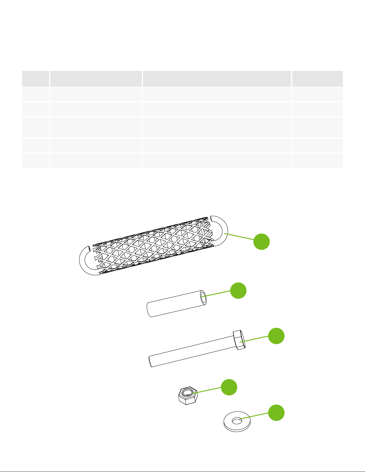
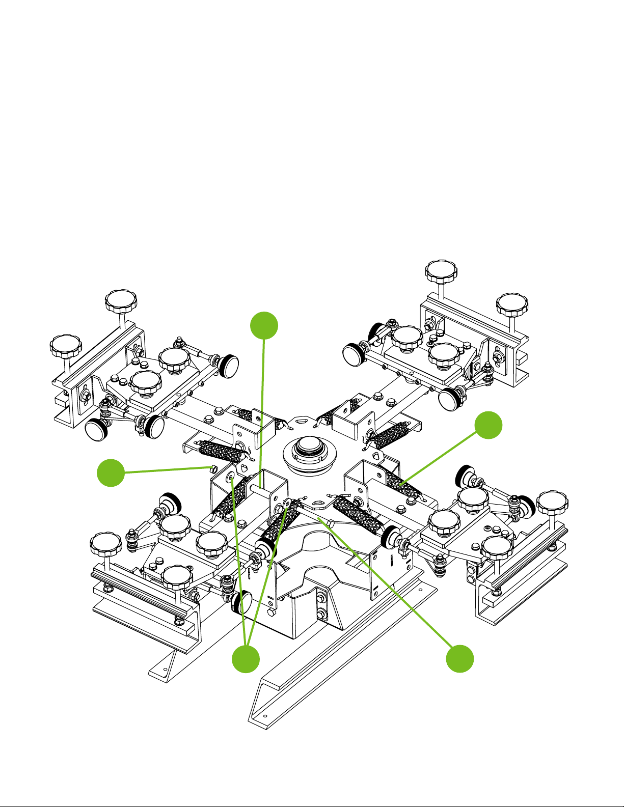
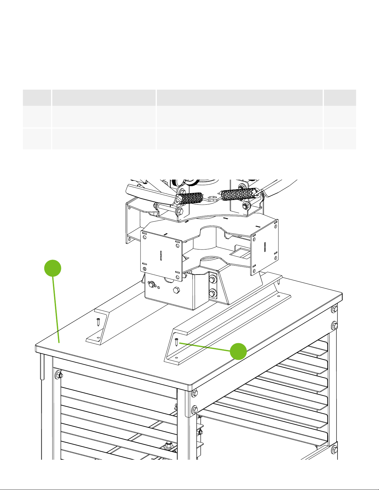
PRCO-RH250SKIT (1 kit per print station)
RILEY 250 PRINT STATION MOUNTING HARDWARE KIT
Tag NAME/ID DESCRIPTION Q.
1PRHD-HC5/16NC1GR5ZC 5/16-18 X 1 HEX TAP BOLT 4
2PRHD-WA5/16USSGR5ZC 5/16 USS FLAT WASHER ZINC 4
3PRHD-WA1/4USSGR5ZC 1/4 USS FLAT WASHER ZINC 4
4PRHD-NYN5/16NCGR5ZC 5/16-18 NYLOC NUT ZINC 4
5PRHD-RP3/16X1ZC 3/16 X 1 ROLL PIN ZINC 2

4
1
2
3
4
5
PRCO-RH250STOPHDWPK
RILEY 250 BUMP STOPHARDWARE
Tag NAME/ID DESCRIPTION Q.
1PRSA-SPRINGKIT MESH COVERED SPRING 2 PER COLOR
2PRCO-BMPRBLTCVRBLU AIR HOSE FOR BUMP STOPS 2” LONG 1 PER COLOR
3PRHD-HC3/8NF3GR5ZC 3/8-24 X 3” HEX CAP SCREW GRADE 5
ZINC 1 PER COLOR
4PRHD-LNYN3/8NFGR5ZC 3/8-24 LOWPRO NYLOC NUT 1 PER COLOR
5PRHD-WA5/16USSGR5ZC 5/16 USS FLAT WASHER ZINC 2 PER COLOR

5
Step 1
Install the spring assemblies with the hooks facing upward. Lower the
Print head assemblies until they rest on the lower stop bolt. Repeat this
step for the remaining print head assemblies.
NOTE: Refer to page 3 for hardware detail.
Hooks MUST
be facing UP
Lower Stop

6
Step 2
Install the upper stop bolts and rubber sleeves. Two 9/16” wrenches
are required for this step. DO NOT OVERTIGHTEN THE BOLTS. This will
cause resistance in the print head hinge point. Repeat this step for the
remaining print head assemblies.
NOTE: Refer to page 3 for hardware detail.
4
53
1
2

7
Step 3
Mount the press base to a sturdy table top (2) with supplied mounting
screws (1). Press is shown mounted on a Riley Hopkins 2-station press
cart (sold separately). A Phillips screwdriver is required for this step.
2
1
Tag NAME/ID DESCRIPTION Q.
1PRCO-JR41MTGHDWKIT MOUNTING HARDWARE PACK PERFORATED
BAG (QTY. 4 SCREWS) 1
2PRAC-JR2STCRT OPTIONAL 2 STATION PRESS CART (SOLD
SEPERATELY) 1

8
Step 4
Install the print stations with supplied hardware. Ensure the number
on the print station matches the number on the center rotary. Failure
to due so, will shi the platens out of alignment. Do not fully tighten at
this time. They must be snug, but loose enough to adjust with bumps of
the hand.
NOTE: Refer to page 2 for hardware detail.
12 3 4
NUMBERS
MUST MATCH
1
1

9
Step 5
Install the 3/16” roll pins to locate the print station. Tap print station to
align holes visually as close as you can. This is a factory seing that
ensures your platens are aligned to each other. Tap them in approx.
½” with a hammer. Aer pins are seated, fully tighten the print station
hardware.
NOTE: Refer to page 2 for hardware detail.
4
3/16”
Roll Pins
1
1

10
Step 6
Install the platen assembly (1) onto the tubular arm of the press. When
platen is in desired location, first lock down the side knob (2). Lastly,
tighten down the lower locking knobs (3). The platen can be adjusted
front-to-back to help position the image onto the desired location of the
substrate.
4
1
3
2

11
Multi-station Press Overview
Riley 250 multi-stations are 12” from the boom of the mounting feet to
the top of the platens. A table height of approx. 23” is recommended to
achieve the common overall platen height of 35” from the ground. Press
is shown mounted on a Riley 250 2 station press cart (Sold separately).
12.00
Platen Height
2
1
3
4
6
5
Tag NAME/ID DESCRIPTION Q.
1PRSA-RH250CLAMP RILEY 250 PRESS CLAMPING HEAD ASSY. 1 PER COLOR
2PRSA-RH250PNTHED RILEY 250 PRINT HEAD ASSEMBLY 1 PER COLOR
3PRHD-HC3/8NC1-
1/2NYBLK 3/8”-16 X 1-1/2 NYLON BOLT BLACK 2 PER STATION
4PLWD-WIN16X16N RILEY HOPKINS PRESS PLATEN ASSY. 1 PER STATION
5PRSA-JRDETBKT RILEY 250 MULTI-STATION DETENT
BRACKET 1 PER UNIT
6PRAC-JR2STCRT OPTIONAL 2 STATION PRESS CART (SOLD
SEPERATELY) 1 PER UNIT

12
76
5
3
2
1
4
8
9
10
PRSA-RH250PNTHD
RILEY HOPKINS 250 PRINT HEAD ASSEMBLY WITH MICRO
Tag NAME/ID DESCRIPTION QTY
1PRCO-KNBRCHT3/8NCFM 3/8 -16 INCH COURSE RATCHET
HANDLES 2
2PRCO-BRNZB3/8ID1/2LG 3/8” X 1” SINTERED BRONZE
BUSHING 2
3MFPD-RH250SPGPLT RH250 COLOR ARM SPRING PLATE 1
4PRCO-RDED5/16RHML 5/16”-24 RIGHT HAND MALE ROD
END 3
5PRHD-SCRWCVR5/16 5/16” RUBBER SCREW COVER 2
6PRCO-KNBKN-
L5/16NF2-3/4ML
1-3/4” KNURLED KNOBS 5/16-24 X
2-3/4” STUD 4
7PRCO-RDED5/16RHFMLS 5/16”-24 RIGHT HAND TREAD
FEMALE ROD END-LONG SHANK 3
8PRHD-WINGNT5/16NF-SS 5/18-24 WING NUT 1
9PRCO-RDED5/16RHFM 5/16”-24 RIGHT HAND FEMALE ROD
END 2
10 PRSA-RH250CLAMP RILEY 250 SCREEN CLAMP
ASSEMBLY 1

While we take pride in our quality and do our best to ensure your satisfaction, Riley Hopkins™/Ryonet®
does not assume any liability for damages, whether consequential or incidental, that may result from the
misuse of below stated specifications.
LIMITED WARRANTY
GENERAL PROVISIONS: The warranties described below apply ONLY to the original purchasers of new
Riley Hopkins™ presses from Ryonet®, purchased on or after April 20, 2013. Under these warranties,
Ryonet® will repair or replace, as Ryonet® elects, covered defective parts, materials, or workmanship
without charge for parts or the reasonable cost of labor related thereto. Ryonet® will use only new or
re-manufactured parts or components furnished by Ryonet® or a Ryonet®-authorized third party.
WARRANTY DURATION: A lifetime warranty shall apply to covered Riley Hopkins™ presses, parts,
components and materials as set forth below.
WHAT IS COVERED: This warranty covers all non-wearable parts, non-wearable components,
and non-wearable materials of new Riley Hopkins™ presses. HOWEVER, the following items are
excluded from the scope of this warranty: expendable parts (including but not limited to bearings,
springs, nylon bolts, oilites and fasteners). FURTHER, Ryonet® does not warrant failure of parts or compo-
nents resulting from misuse or lack of proper maintenance, or improper installation.
WHAT IS NOT COVERED: Installation, inspection, and routine maintenance costs are the sole responsi-
bility of the purchaser; used equipment; any equipment modified or altered in any way not approved by
Ryonet® in writing including, but not limited to, disassembling bearing components; routine maintenance
and lubrication; consequences of negligence, misuse, accident, or improper application, installation, or
storage of the press; consequences of any service performed by someone other than a Ryonet®-autho-
rized provider.
SECURING WARRANTY SERVICE: Warranty service must be requested of the nearest Ryonet® location.
At the time of requesting warranty service, the person or entity requesting warranty service must be
prepared to present evidence that it was the original purchaser of the Riley Hopkins™ press(es).
Written authorization must be obtained from Ryonet® before any part will be accepted. In order to
return such defective part, contact Ryonet® to return such part freight prepaid. Replacement parts are
sent out freight collect. Parts sent out prior to receiving defective part will be sent C.O.D., cost plus
freight. Upon return of defective part, if it is deemed that the part was not damaged by customer but
failed, the cost of the replacement part will be refunded.

14

Riley Hopkins® - 1-360-576-7188 - WWW.RILEYHOPKINS.COM
PRTB-RH250-MULTI_ 092022_A
Other manuals for 250
1
Table of contents
Popular Power Tools manuals by other brands

TE Connectivity
TE Connectivity 2390881-1 instruction sheet

Baumr-AG
Baumr-AG CHNSHPBMRA02K user manual

Makita
Makita SG1250 instruction manual

Gude
Gude GDS 150 L Translation of the original instructions

Harbor Freight Tools
Harbor Freight Tools 40939 Owner's manual & safety instructions

Makita
Makita ST113D instruction manual