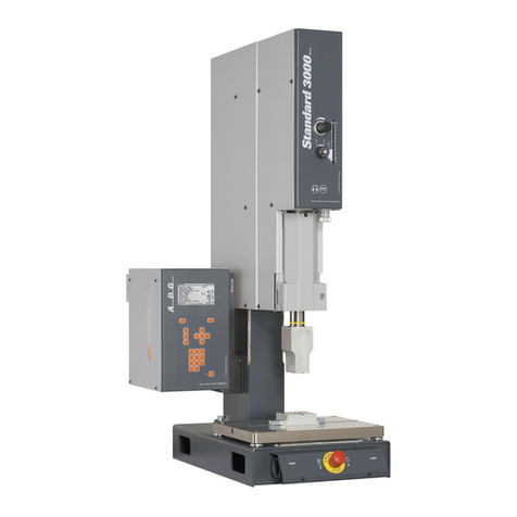
RINCO ULTRASONICS AG HW35-3 User manual

Operating Manual
English
Ultrasonicweldingdeviceforplastics
................. RINCO ULTRASONICS AG
Industriestrasse 4
CH-8590 Romanshorn
Switzerland
............................... ++41 71 466 41 00
............................... ++41 71 466 41 01
Hand welding device HW35-3
with
Generator RL35
Version 4.0 RL35HW/NO7768
RL35 HW35-3

RL35HWV40/GB/NO7768/16279
Copyright by RINCO ULTRASONICS AG, Switzerland
Note
Device specification
Note
Readthisoperatingmanual andstudy it
carefully before unpacking and putting
the device into operation.
The device may only be used, maintai-
ned and repaired by persons who are
familiar with the operating manual and
the applicable regulations concerning
workingsafetyandaccidentprevention.
Sticker
Device
Representative
Sticker
Generator

RL35HWV40/GB/NO7768/16279
I
Table of contents
1 Explanation of symbols and signs.......................................................................1-1
2 Safety information .................................................................................................2-1
2.1 General ....................................................................................................................................2-1
2.2 Intended purpose .....................................................................................................................2-1
2.3 Special points to note ...............................................................................................................2-1
2.4 Choosing staff ..........................................................................................................................2-1
2.5 Installing the device ..................................................................................................................2-2
2.6 Operation .................................................................................................................................2-2
3 Product information ..............................................................................................3-1
3.1 Productoverview ......................................................................................................................3-1
3.1.1 Hand held cutting device ..............................................................................................3-1
3.1.2 Ultrasonic generator RL35 ...........................................................................................3-1
3.1.3 Cooling(optional) .........................................................................................................3-2
3.2 Warranty statement ..................................................................................................................3-3
3.3 Technical data device HW35-3 .................................................................................................3-4
3.3.1 Concept........................................................................................................................3-5
3.3.2 Compressed air............................................................................................................3-5
3.3.3 Dimensions ..................................................................................................................3-5
3.3.4 Weight..........................................................................................................................3-5
3.3.5 Connecting cables........................................................................................................3-5
3.4 Technical data of the Ultrasonic Generator RL35 .....................................................................3-6
3.4.1 Concept........................................................................................................................3-7
3.4.2 Available generator modules ........................................................................................3-7
3.4.3 Connected loads ..........................................................................................................3-7
3.4.4 Dimensions ..................................................................................................................3-7
3.4.5 Weight..........................................................................................................................3-7
4 Transportation .......................................................................................................4-1
4.1 Unpacking/receivinginspection ................................................................................................4-1
4.2 Damage during transit ..............................................................................................................4-1
4.3 Positioning the device...............................................................................................................4-1
5 Controls and indicators ........................................................................................5-1
5.1 Hand held welding device.........................................................................................................5-1
5.2 Ultrasonic Generator RL35.......................................................................................................5-2
6 Initial start-up .........................................................................................................6-1
6.1 Choice of location.....................................................................................................................6-1
6.2 Assembling and connecting up the devices..............................................................................6-1
7 Elements.................................................................................................................7-1
7.1 Converter .................................................................................................................................7-1
7.3 Horn .........................................................................................................................................7-2
7.3.1 Horn materials..............................................................................................................7-2
8 Retooling ................................................................................................................8-1
8.1 Changing horn..........................................................................................................................8-1
8.2 Detailed description of functions from the program selector switch ..........................................8-2
8.2.1 Before changing a program..........................................................................................8-2
8.2.2 Afterpulse (shake-off impulse) .....................................................................................8-4
8.2.3 Soft Start ......................................................................................................................8-4

RL35HWV40/GB/NO7768/16279
9 Cleaning and maintenance ...................................................................................9-1
9.1 General maintenance jobs .......................................................................................................9-1
9.2 Hand held welding device.........................................................................................................9-1
9.3 Generator .................................................................................................................................9-1
9.4 Vibration system .......................................................................................................................9-2
9.5 Threaded coupling....................................................................................................................9-2
10 Error messages and trouble shooting...............................................................10-1
10.1 Error messages / corrective action: switching on....................................................................10-1
10.2 Generator error messages during operation...........................................................................10-1
11 Electrical diagrams ............................................................................................. 11-1
11.1 Wiring diagram for housing ....................................................................................................11-1
11.1.1 Start ST02 automatic (standard) ................................................................................ 11-1
11.1.2 Start ST02 manual (optional)......................................................................................11-2
11.1.3 Start ST02 manual (optional)......................................................................................11-2
11.1.4 Interface ST03 ...........................................................................................................11-3
11.1.5 Generator module UGF..............................................................................................11-4
11.2 Fuses Generator RL35...........................................................................................................11-5
11.3 List of fuses Generator RL35 .................................................................................................11-6
11.3.1 Fuses 230 volt / 200 volt ............................................................................................11-6
11.3.2 Fuses 110 volt ............................................................................................................11-6
11.4 RL 35 Generator rear panel.................................................................................................... 11-7
11.5 List of device sockets and connection plugs...........................................................................11-7
12 Technical drawings and values..........................................................................12-1
12.1 Amplitude values of the generator RL.....................................................................................12-1
12.2 Amplitudes of 35 kHz RL generators ......................................................................................12-1
12.2.1 Amplitudes with amplified converter ...........................................................................12-1
12.3 Stud length of the vibration components; 35 kHz....................................................................12-2
13 Service center addresses ...................................................................................13-1
II
Table of contents

RL35HWV40/GB/NO7768/16279
III
Chapter Safety information
Contains notes and warnings
concerning the operation of the
welding system.
Chapter Product information
Contains all the general informati-
on concerning:
- function, design and mode of
operation
- technical data
- warranty
Chapter Transportation
Contains necessary information on
the transportation and receipt of
the device.
Chapter Operating and display elements
Describes the operating elements.
Chapter Initial start-up
Provides important notes and
instructions concerning the instal-
lation, connection and start-up of
the device. Includes all the infor-
mation and procedures necessary
for the safe and efficient handling
of the device.
Chapter Elements
Describes the various exchangea-
ble elements.
Chapter Retooling
Describes how to change a horn
or booster.
Chapter Cleaning and maintenance
Contains instructions and notes
concerning the care and upkeep of
the device.
Chapter Error messages and corrective
action
Describes possible errors, their
likely sources and suggestions for
corrective action.
Other chapters Diagrams and drawings
Preface
Congratulations on having purchased the device.
This manual is designed to provide buyers and users
withallthe informationtheywillneedtohandle,install,
operate and maintain the device.
To ensure that the system is always ready for opera-
tion,itisnecessarytofollowthenotesandinstructions
in this manual.
The manual is broken down into the following chap-
ters:
Preface

RL35HWV40/GB/NO7768/16279
IV
Important!
Pleasequotetheexacttypedesignation and
the device serial numbers in all enquiries
concering your device.
Youwillfindthisdataontheratingplate(A)at
thebackofthedevice,aswellasontheinside
cover flap of this operating manual.
The design and circuitry of this device are
subject to continuous further development
and improvement, and represent the latest
state of the art.
RINCO ULTRASONICS AG
Romanshorn,Switzerland
Important

RL35HWV40/GB/NO7768/16279
V
Notes
#
___________________________________________________________________
___________________________________________________________________
___________________________________________________________________
___________________________________________________________________
___________________________________________________________________
___________________________________________________________________
___________________________________________________________________
___________________________________________________________________
___________________________________________________________________

RL35HWV40/GB/NO7768/16279
Notizen
#
___________________________________________________________________
___________________________________________________________________
___________________________________________________________________
___________________________________________________________________
___________________________________________________________________
___________________________________________________________________
___________________________________________________________________
___________________________________________________________________
___________________________________________________________________
VI

RL35HWV40/GB/NO7768/16279
1-1
Explanation of symbols and signs
1 Explanation of symbols and signs
Special attention should be paid to passages with the following
symbols:
Special information or operating instructions.
Warnings regarding risk of personal injury or damage to
parts of the equipment.
Theitemnumbersusedintheillustrationsanddescriptions,e.g.:
Generator module grips (26)
correspond to the item numbering adopted in the product over-
viewincludedinthechapter"Productinformation",ortoadjacent
drawings, generally on the same page.

1-2
RL35HWV40/GB/NO7768/16279
Explanation of symbols and signs
#
___________________________________________________________________
___________________________________________________________________
___________________________________________________________________
___________________________________________________________________
___________________________________________________________________
___________________________________________________________________
___________________________________________________________________
___________________________________________________________________
___________________________________________________________________

RL35HWV40/GB/NO7768/16279
2-1
Safety information
2 Safety information
2.1 General
The design of this device conforms to the current state of
engineering and is safe to operate.
The individual modules and the completedevice are subject to
continual inspection by our quality assurance department.
2.2 Intended purpose
This device is intended exclusively for the ultrasonic welding of
suitable plastics. Any other use is regarded as inconsistent with
the intended purpose, and is undertaken at the user's own risk.
The manufacturer is not liable for any resultant damage.
Intended for industrial use.
2.3 Special points to note
Beforeyoustartupthedeviceforthefirsttime,readthisoperation
manual carefully.
Being badly informed about how to operate and look after the
device can result in damage.
Alwayskeeptheoperatingmanualhandyatthesiteofthedevice.
Donot perform any modifications, extensions or conversions on
the device which might endanger safety without the supplier's
consent.
Donotaltertheprogramming(software)ofprogrammablecontrol
systems.
2.4 Choosing staff
Work on the electrical installations of the device may only be
performedby anelectricalspecialist orinstructedstaff underthe
management and supervision of an electrical specialist, accor-
ding to electrical engineering standards.

2-2
RL35HWV40/GB/NO7768/16279
Safety information
2.5 Installing the device
Always unplug the power cable before making any
connections to peripheral devices.
Be sure to fit the power supply with a grounding connector!
Observe any statutory safety regulations in force in
your country!
Failure to observe these regulations will exempt the
manufacturerfromallliabilityforinjurytopersons or
damage to materials!
Before starting up the device, always make sure it is in a closed
and safe condition.
2.6 Operation
Neveropenthegeneratoror converter housingwhile
the device is in operation.
There is a high voltage inside the device - risk of
injury!
Avoid any potentially unsafe working practices.
Correct operation and careful handling of the devices and their
associated tools during operation will
- keep the system ready for service,
- prolong its useful life, and
- reduce stoppage times to a minimum.

RL35HWV40/GB/NO7768/16279
2-3
Safety information
#
___________________________________________________________________
___________________________________________________________________
___________________________________________________________________
___________________________________________________________________
___________________________________________________________________
___________________________________________________________________
___________________________________________________________________
___________________________________________________________________
___________________________________________________________________

2-4
RL35HWV40/GB/NO7768/16279
Safety information
#
___________________________________________________________________
___________________________________________________________________
___________________________________________________________________
___________________________________________________________________
___________________________________________________________________
___________________________________________________________________
___________________________________________________________________
___________________________________________________________________
___________________________________________________________________

RL35HWV40/GB/NO7768/16279
3-1
Product information
3 Product information
3.1 Product overview
3.1.1 Hand held cutting device
1 Housing
2 Trigger switch
3 Horn
4 Suspension
5 Cooling-airconnections
A Name plate on housing
1
23.1.2 Ultrasonic generator
RL35
26 Generator module handle
26.1 Modeldesignation
27 LED bar
28 LED, power
29 Function key "US-TEST"
30 Status displays
US ON (green)
VALVE (green)
ERROR (red)
31 Weld time
32 Hold time
33 Fastening screws
34 Mains switch

3-2
RL35HWV40/GB/NO7768/16279
Product information
3
3.1.3 Cooling (optional)
Itisnecessaryto cool the
converter for heavy duty
use.
5 Connection for hose ÿ 4

RL35HWV40/GB/NO7768/16279
3-3
Product information
3.2 Warranty statement
With the delivery of this system RINCO ULTRASONICS AG
acknowledges its warranty obligation in accordance with VSM
(Association of Swiss Machine Builders).
Fulfilment of the terms of this warranty by RINCO ULTRASO-
NICS AG shall be conditional, however, on a number of require-
ments, for example:
The user must be familiar with the contents of this
Operating Manual.
TheinstructionsandwarningscontainedinthisOpe-
rating Manual must be observed.
Unauthorized conversions or modifications to parts
of the device and generator are prohibited.
RINCO ULTRASONICS AG shall be glad to clarify any unlcear
points on the phone or to provide instruction by capable specia-
lists.

3-4
RL35HWV40/GB/NO7768/16279
Product information
3.3 Technical data
device HW35-3
Dimensions in mm
5

RL35HWV40/GB/NO7768/16279
3-5
Product information
3.3.1 Concept
- Robust handy housing
- Ergonomic trigger switch
- Piezoelectricconverter
- Connecting screw thread for horn:................................... M8
3.3.2 Compressed air
- Dry compressed air, maximum:.................... 7 bar (105 PSI)
3.3.3 Dimensions
- Dimensions:................................................ see fig. page 3-4
3.3.4 Weight
- Weight ................................................................... ca. 0.7 kg
3.3.5 Connecting cables
- Standard length: .............................................................. 3m
- Other lengths:........................................................... to order

3-6
RL35HWV40/GB/NO7768/16279
Product information
3.4 Technical data of
the Ultrasonic Gene-
rator RL35
Dimensions in mm
Weight: ................................ 7 kg
6
This manual suits for next models
1
Table of contents
Other RINCO ULTRASONICS AG Welding System manuals
Popular Welding System manuals by other brands

WELDKAR
WELDKAR WK TIG 2025 AC/DC Pulse instruction manual

CEMONT
CEMONT SPEEDY 130 Safety instruction for use and maintenance

Renegade
Renegade RIMIG205I instruction manual

Lincoln Electric
Lincoln Electric INVERTEC V160 Operator's manual

lamart
lamart PUK D5 operating manual

Jasic
Jasic TIG315PACDC(E202) Operator's manual