RINGSPANN RLK 608 Supplement

Schaberweg 30-34
Telephone +49 6172 275-0
Telefax +49 6172 275-275
www.ringspann.com
61348 Bad Homburg
Germany
Installation and Operating Instructions for
Shrink Discs RLK 608 and RLK 608 E
E 03.621e

Installation and Operating Instructions
for Shrink Discs RLK 608 and RLK 608 E
E 03.621e
issue: 26.10.2018
version : 09
drawn: REIW
checked: EISF
Pages : 6
page: 2
Important
Please read these instructions carefully before installing and operating the product. Your particular
attention is drawn to the notes on safety.
These installation and operating instructions are valid on condition that the product meets the
selection criteria for its proper use. Selection and design of the product is not the subject of these
installation and operating instructions.
Disregarding or misinterpreting these installation and operating instructions invalidates any product
liability or warranty by RINGSPANN; the same applies if the product is taken apart or changed.
These installation and operating instructions should be kept in a safe place and should accompany
the product if it is passed on to others -either on its own or as part of a machine- to make it
accessible to the user.
Safety Notice
Installation and operation of this product should only be carried out by skilled personnel.
Repairs may only be carried out by the manufacturer or accredited RINGSPANN agents.
If a malfunction is indicated, the product or the machine into which it is installed, should be
stopped immediately and either RINGSPANN or an accredited RINGSPANN agent should be
informed.
Switch off the power supply before commencing work on electrical components.
Rotating machine elements must be protected by the purchaser to prevent accidental contact.
Supplies abroad are subject to the safety laws prevailing in those countries.
This is a translation of the German original version!
In case of inconsistencies between the German and English version of this
installation and operating instruction, the German version shall prevail.

Installation and Operating Instructions
for Shrink Discs RLK 608 and RLK 608 E
E 03.621e
issue: 26.10.2018
version : 09
drawn: REIW
checked: EISF
Pages : 6
page: 3
1. General information
1.1 Function:
RLK 608 shrink discs are used to effect friction-tight, no-play connections between hollow shafts
and shaft ends for the purpose of transmitting torque, shear and axial forces.
1.2 General safety instructions:
Caution! Danger of injury!
The immediate vicinity of the rotating shrink disc must be kept clear of body
parts, hair, clothing and other objects at all times.
2. Configuration and function
These installation and operating instructions are valid for Shrink Discs RLK 608 and RLK 608 E. The
RLK 608 shrink disc consists of an outer stepped conical ring and an inner stepped conical bushing,
as well as a number of clamping screws. The stepped conical ring is pulled onto the stepped conical
bushing by tightening the clamping screws. A radial clamping force is generated by the conical
surfaces, which is independent of the friction coefficients at the screws and conical surfaces. The
radial clamping force presses the hollow shaft onto the shaft and creates a frictional connection at the
contact surfaces beween the shaft and the hollow shaft. Thereby, torque and/or axial forces can be
transmitted between the shaft and the hollowshaft
During the clamping process, the position of the stepped conical bushing relative to the hollow shaft
remains unchanged. The connection is released by tightening clamping screws in the threaded bores
for the jacking screws.
3. Cross-sectional diagram and parts list
Picture 3.1

Installation and Operating Instructions
for Shrink Discs RLK 608 and RLK 608 E
E 03.621e
issue: 26.10.2018
version : 09
drawn: REIW
checked: EISF
Pages : 6
page: 4
4. Purpose and proper use
RLK shrink discs are external clamping elements. They are designed exclusively for rigid hollow-
to-solid shaft connections for the purpose of transmitting torque and axial forces through friction-
tight connection. Use for any other purpose is regarded as improper use. RINGSPANN shall not
be liable for damages resulting from improper use. All resulting risks shall be borne by the user.
5. Improper use
RLK shrink discs are not suitable for use:
as torque-limiting safety devices.
6. Condition on delivery
The shrink discs are delivered ready for installation. They have been sprayed with rust-proofing
oil and are wrapped in anti-corrosion paper.
7. Technical requirements for safe operation
In order to ensure full transmission of torque and axial forces, the fitting tolerance for the outside
diameter of the hollow shaft must not exceed tolerance class f7.
It is also important to ensure compliance with the following clearance combinations between the
hollow shaft bore and the outside diameter of the shaft:
Other diameter of solid shaft dW
Hollow shaft
bore
ISO
Solid shaft
diameter
ISO
Joint clearence
>
mm
≤
mm
min.
mm
max.
mm
24
30
0
0,034
30
50
0
0,041
50
80
H7
h6
0
0,049
80
120
0
0,057
120
160
0
0,065
160
180
0,014
0,079
180
250
H7
g6
0,015
0,090
250
315
0,017
0,101
315
390
0,018
0,111
Failure to adhere to these fitting tolerances may
cause changes in transmissible torques and/or axial forces and
render proper installation impossible.
In addition, the contact surfaces of the shaft ends and hollow shaft must have a mean
roughness depth of Ra≤ 3,2 µm.
Shaft and the hollow shaft must be manufactured from materials with the following mechanical
properties:
Yielt strength Re≥360 N/mm2
E-module about 206 kN/mm2
The MoS2paste between the tapered surfaces of the inner segment and outer segment, on the
threads and unter the head of the screws must not be removed. Proper installation is not possible
without this MoS2paste.

Installation and Operating Instructions
for Shrink Discs RLK 608 and RLK 608 E
E 03.621e
issue: 26.10.2018
version : 09
drawn: REIW
checked: EISF
Pages : 6
page: 5
8. Installation
8.1 Clean the hollow shaft bore and the shaft thoroughly to remove all dirt, oil and grease and
ensure a friction coefficient of µ ≥ 0,15 on all contact surfaces. This surfaces are not allowed
to oil or grease.
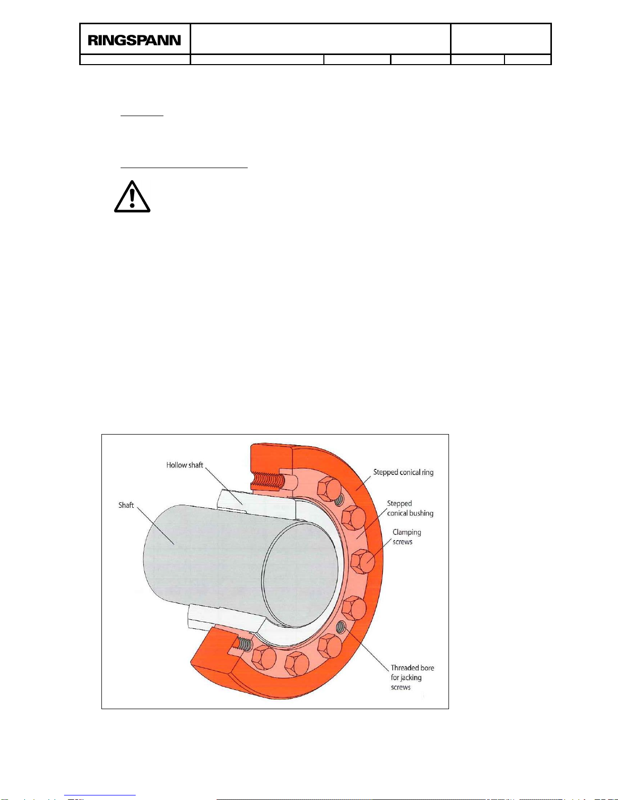
8.2 Apply a light coat of grease to the outer diameter of the hollow shaft at the point at which the
shrink disc is positioned (picture 8.1, diameter d).
8.3 Insert the shaft into the hollow shaft.
8.4 Push the shrink disc onto the hollow shaft.
A shaft must always be inserted in the hollow shaft when mounting the shrink
disc!
8.5 Tighten the clamping crews by hand. Then tighten all screws with a suitable tool in a
clockwise sequence, turning each screw by a ¼ revolution in each step.
8.6 Continue to tighten the clamping screws uniformly in sequence by
a ¼ revolution until the stepped tapered ring and the stepped
tapered bushing are flush with the screw-side face.
Note: When installing shrink discs with slotted stepped tapered
bushing, begin with the screw to the left of the slot and
tighten the screws as described in Section 8.6.
Installation is distance-controlled. Therefore, it is not
necessary to use a torque wrench!
Replace missing or damaged clamping screws with
equivalent screws of quality grade 12.9 only, grease new
screws like described under 10.2!
9. Disassembly
9.1 Loosen the clamping screws uniformly in multiple steps by ¼ revolution for each step to
prevent misalignment of the clamping surfaces and breaking of screws.
Do not remove clamping screws completely from threaded bores under any
circumstances, as this poses the risk of injury.
9.2 Do not separate the two rings directly. Instead, remove as many clamping screws as
threaded press-off bores in the stepped tapered bushing and turn them into the press-off
bores uniformly until the stepped tapered ring is pressed free of the stepped tapered
bushing.
9.3 Remove the shrink disc from the hollow shaft.
Picture 8.1

Installation and Operating Instructions
for Shrink Discs RLK 608 and RLK 608 E
E 03.621e
issue: 26.10.2018
version : 09
drawn: REIW
checked: EISF
Pages : 6
page: 6
10. Remounting removed shrink discs
Please observe the following instructions when reusing previously removed shrink discs:
10.1 Completely dismantle the shrink disc and clean thoroughly to remove residues of lubricants
applied to the tapered surfaces by the manufacture prior to delivery.
Shrink discs with damaged tapered surfaces may not be reused and must be
replaced with fully functional elements.
It is essential to ensure that the original pairing of stepped tapered bushing
and stepped tapered ring remains intact following cleaning and lubrication.
10.2 Lubricate the tapered surfaces of the cone ring, the threads of the clamping screws and head
contact surfaces thoroughly with MoS2paste (“gleitmo 100“ from FUCHS LUBRITEC (www.
fuchs-lubritec.de) or a molybdenum-sulphide lubricant of equivalent quality).
11. Maintenance
RLK 608 shrink discs are maintenance free. However, signs of settling may appear in
connections during operation. We therefore recommend checking the tightness of the clamping
screws each time maintenance is performed on the machine
This manual suits for next models
1
Table of contents
Popular Tools manuals by other brands

Hilti
Hilti SCO 6-22 operating instructions

SUHNER ABRASIVE
SUHNER ABRASIVE USK 6-R Technical document

Utility Solutions
Utility Solutions LOAD-RANGER USLR-XLT-1 Operation manual

Hewlee
Hewlee HL-300B instruction manual

Huskie Tools
Huskie Tools SL- 610 Operation manual

HOLZMANN MASCHINEN
HOLZMANN MASCHINEN PJ 100PRO user manual