Rio Grande NEUTEC J-2r Service manual

™
Rev. F
710-990
©2013 Neutec/Rio Grande™
7500 Bluewater Road NW
Albuquerque, NM, 87121 USA
Technical Support: 505.839.3558
Neutec™ Sales: 505.839.3010 • Fax 505.839.3016
Neutec™
J-2r
Operator’s Handbook
Important!
Please read this handbook
before using your Neutec/Rio Grande™ J-2r.


www.neutec.com Page iii
Contents
Section One
About Your Neutec/Rio Grande™J-2r
Introduction 1-1
Site Requirements 1-2
Features 1-2
Section Two
Safety
Introduction 2-1
Recommended Safety Gear 2-2
General Safety Warnings 2-3
Compressed Gas 2-3
Environmental Concerns 2-4
Fire Extinguisher Equipment 2-4
Section Three
Set-Up
Start-Up Kit 3-1
Setting Up Your J-2r3-2
Section Four
Crucible Chamber Parts
Removing the Hood 4-1
Removing the Filling Cone 4-1
Removing the Crucible Chamber Parts 4-2
Installing the Crucible Chamber Parts 4-2
Section Five
Sealing Rod
Replacing a Sealing Rod Ball 5-1
Removing the Sealing Rod Assembly 5-3
Adjusting the Sealing Rod Tension 5-4
Section Six
Installing the Thermocouple 6-1
Section Seven
Installing the Stirring Rod 7-1
Section Eight
Operating the Temperature Controller
Setting the Casting Temperature 8-1
Setting the Casting Balance 8-2
Section Nine
Casting With Your J-2r
Startup Checklist 9-1
Starting the J-2r9-1
Charging the Crucible with Metal 9-2
Positioning the Flask 9-3
Casting 9-4
Shutting Down 9-6
Appendices
A NeuSprue™ Wax-to-Metal
Weight Conversion
BController Parameters
CJ-2rParts and Accessories
DAlloy Melting Points
ETroubleshooting
F Revision History


www.neutec.com About Your J-2rPage 1-1
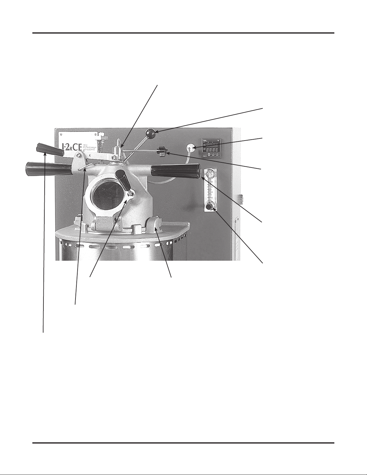
Section One: About Your J-2r
Introduction
The J-2rfrom Neutec/Rio Grande™ incorporates
many of the important casting features found in
the Neutec™systematic approach to casting. It is
resistance-heated, meaning that it uses a
low-voltage electric coil to heat the melting
crucible, and has a sophisticated temperature
controller. The J-2r is an excellent choice for the
craftsman/designer working out of a small shop
where high production levels are not a daily
necessity. Cost/benefit ratios make it possible to
own a J-2reven when one-of-a-kind casting is
the majority of your workflow. The J-2rincludes:
• Accurate temperature control.
• PID fuzzy logic controllers
• Protective inert-gas (nitrogen or argon)
atmosphere prevents oxidation.
• Bottom-pour crucible preserves metal
temperature during the pour and leaves any
slag or other contaminants in the button,
not in your casting.
• Closed-system stirring of alloys maintains
the protective atmosphere in the crucible.
• Low-voltage coil prevents electrical shock
and provides a long service life.
After initial heat up, casting cycles average
about 8 minutes, depending on metal type and
load size. The entire cycle assumes an attentive
operator reading the display and taking the
appropriate actions at the appropriate times.
Crucible Capacity: The maximum working
capacities of the J-2rare shown in the following
chart. Working capacity (the amount of casting
grain the crucible can hold before melting) is
approximately 60% of the crucible liquid
capacity. The working capacity varies depending
on the size and shape of your casting grain.
Metal Working Capacity
(grams) (dwt)
24KY 1,300 850
18KY 1,050 650
14KY 900 550
10KY 750 500
Sterling 700 450
J-2r crucible working capacity
Melting Time: For an initial cycle, starting
with a cool crucible, heating time is about 40
minutes; subsequent casting cycles range from
6–8 minutes depending on the size of the load.
Maximum Flask Size:
102mm diameter x 229mm H (4" dia. x 9"H).
Power Requirements: 208–240 volts, single-
phase, 1.5kW; requires a 15-amp circuit with
a circuit breaker.
Inert Gas Requirements: Nitrogen or argon;
8 lpm minimum at 0.7 bar (10 psi).
Important! Gas must be pure and
contain no oxygen or any combustible gas.
Dimensions: 46cmW x 46cmD x 76cmH
(18"W x 18"D x 311/2"H).
Weight: 54kg (119 lbs.);
shipping weight: 60kg (132 lbs.).
Vacuum Requirements: one external 5cfm
vacuum pump.

505.839.3010 Neutec/Rio Grande™ J-2rRev. F Page 1-2
Site Requirements
Maximize the benefits of the J-2rby making
sure these site requirements are met:
• Install the machine in a well-ventilated area.
• Do not place the machine on or near
flammable materials.
• Allow at least 25cm (10") of clearance
on all sides of the machine.
• Make sure the J-2rhas its own electrical
circuit. If you are not sure your electrical
supply is compatible with the machine’s
requirements, consult an electrician.
• Temperature
Controller
Indicates/controls
metal temperature
casting temperature
• Nitrogen flow meter
Indicates gas flow
in liters per minute
Nitrogen Input Port
Attach nitrogen
supply to this port
with supplied fittings
Main Power Switch
Activates machine
power
Vacuum Pump
Hose Connection
Vacuum pump hose
connection point
Flask Chamber
Locking Lever
Locks the flask chamber
firmly against the crucible
chamber
Vacuum Gauge
Indicates vacuum is
being pulled on a flask
Flask Chamber
Swings out to accept
a flask up to 102mm
x 229mm (4" x 9")
Crucible Chamber
Melts the metal
in a bottom-pour
graphite crucible
Flask Chamber
Handle
Opens flask chamber
after it is unlocked
Crucible Chamber
Hood Handles
Turns hood to unlock it
to be lifted off of machine
Features

www.neutec.com About Your J-2rPage 1-3
Stirring Handle
Connects to the graphite
stirring rod in the crucible
• Sealing Rod Holder
Holds the sealing
rod assembly and
thermocouple
Thermocouple Receptacle
Holds the type-K
thermocouple
Hood Hold-Down Lug
Secures the hood with
tabs that slide under this
hook-shaped lug
Sealing Rod Lifting Lever
Pushing down lifts sealing
rod assembly to release
the metal into the flask
Hood Door
Opens for adding
metal to the crucible
Sealing Rod Locking
Collar
Turns to lock collar on
tube for proper sealing
rod tension; allows turning
of the rod to seat it in the
crucible
Locking Mechanism
Locks sealing rod
in the up position
Heating Coil On Light
(Behind handle) Indicates
power is on to the coil and
it is heating
Nitrogen Flow
Adjustment Knob
Indicator is a small black
bead in center of gauge;
shows liters per minute
Features (continued)


www.neutec.com Safety Page 2-1
Section Two: Safety
The J-2ris specifically designed to melt
common jewelry metals (except platinum)
and their alloys at or below 1200°C (2192°F) and
to cast these metals into investment molds
using the lost-wax method.
These metals or alloys must contain only
the following elements:
• gold (Au) • nickel (Ni) • gallium (Ga)
• silver (Ag) • palladium (Pd) • silicon (Si)
• copper (Cu) • tin (Sn) • boron (B)
• zinc (Zn) • indium (In) • zirconium (Zr)
• cobalt (Co) • iridium (Ir) • ruthenium (Ru)
The Neutec™ J-2rcan be serviced or
modified only by a Neutec-qualified
Field Service Engineer (FSE). This machine
is a safe and powerful tool when operated
as intended. It can become dangerous if
improperly modified, abused, or used for
any other application. The J-2ris designed
to work with Neutec consumables. Using
consumables not manufactured by Neutec will
result in poor castings and can cause damage
to the machine. Non-Neutec crucibles will not
perform well and can cause carbon inclusions in
your castings.
Please read the following information carefully
and completely before attempting to install,
use, or maintain your J-2rcasting machine.
Failure to comply with these cautions may
result in serious personal injury and/or
property damage. Protect yourself and others
by observing all safety rules at all times.
Safety Symbol Meanings
Wear Protective Apron
Wear Protective Shoes
Wear Protective Gloves
Wear Hearing Protection
Wear Full Face Protection
Do Not Touch
Keep Dry
Alert / Warning / Use Caution
Hot—Will Cause Burns
Danger of Electrical Shock
Danger of Fire
Danger of Explosion
Danger of Electrical Shock If Wet

505.839.3010 Neutec/Rio Grande™ J-2rRev. F Page 2-2
Recommended Safety Gear and Devices
Neutec/Rio Grande™recommends the following safety gear and devices be used
at all times to minimize the risk of injury to the operator and observers.
Item Description Neutec/Rio Grande™
Order #
Lightweight Face shield gives complete face and neck protection. a. Headgear and shield:
Face Shield Allows full, unrestricted vision and has fully 201-746
adjustable headgear. b. Shield only: 201-747
Safety Glasses Glasses with polycarbonate lens material and side 115-729
guards.
Protective Wear only clothing made of cotton or wool. Clothing *
Clothing made from man-made fibers will melt and stick to
your skin if it comes in contact with hot metal or
flames.
Asbestos-Free Flame-resistant gloves made from Kevlar® thermal 704-105
Casting Gloves material. Contain no fiberglass or asbestos.
45.7cm (18") elbow length.
Protective Leather shoes or boots with built-in, steel toe *
Shoes protection.
Flask Tongs These special flask tongs lessen the chance of injury 710-568, 710-551
to workers and damage to flasks. They help reduce 710-569, 710-571
hand and wrist strain. With larger and heavier flasks,
the operator has a secure grasp on the flask.
Crucible Cooling jar cools a hot crucible and gives it longer 710-527
Cooling Jar life. Holds any Neutec™crucible
Crucible For hot crucible changes, use these special tongs. 710-208
Tongs Tongs are designed to safely open and close the
crucible cooling jar.
Graphite Use the rod to stir molten metal in the crucible, Rod: 710-034
Stirring Rod ensuring homogeneity. Holder: 710-207
& Rod Holder
Respirator Lightweight half-mask, NIOSH-MSHA approved. 201-683
Cartridge for above mask meets NIOSH 42 CFR 84
P100 requirements. Protects against respirable silica,
metal fumes, dust, fumes, radio nuclides, and airborne
asbestos.
Heavy-Duty 710-529
Tweezers
*Not available from Neutec/Rio Grande.

www.neutec.com Safety Page 2-3
General Safety:
• Neutec recommends always using
appropriate safety gear and devices to
avoid personal injury to yourself and to
those around you. Please refer to the chart
of safety gear and devices on the facing
page.
• Verify that all guards and doors are in place
before operating the machine to avoid
injury to the operator.
• The hood-door glass is very hot during
machine operation.
•Warning! If you touch the hood-door
glass while the machine is operating, you
will be burned.
• The parts inside the crucible and flask
chambers are very hot while the machine
is operating.
•Warning! If you touch hot parts, you will
be burned. Be very careful when removing
and handling hot crucible chamber parts
and flask adapters. Use the appropriate
safety gear and devices as recommended
by the manufacturer.
• Do not put water or wet metal into the
machine. Moisture added to hot metal will
cause a steam explosion which can eject
hot or molten metal from the machine and
injure you or others nearby.
• Overheating the metal in the crucible can
result in metal splatter that can cause
serious burns. Follow the operating
instructions carefully to avoid overheating
the metal.
• Follow the Neutec™ specifications regarding
size, shape, and physical properties of metal
to be put into the crucible.
• Follow the correct operating procedure
sequences as specified by Neutec™. Failure
to observe proper procedures can render
the J-2runsafe to operate.
• Use only genuine Neutec™replacement
parts and consumables to ensure correct
operation of the machine and to avoid
serious personal injury.
• Unplug the machine whenever you are
performing maintenance on it. Restore
machine power with the main switch in
the OFF position to avoid a surge of current.
• Acquaint yourself with the Material Safety
Data Sheets applicable to the machine.
These are available from Neutec™.
Handling and Use of Compressed Gas
Cylinders and Pressure Regulators
Neutec/Rio Grande™ casting machines require
inert gas to provide an oxygen-free atmosphere
in the crucible and flask chambers. Nitrogen or
argon can be used for this purpose.
•Warning! In this handbook, the use of the
term “gas” does not refer to natural gas, stove
gas, or any other combustible gas.
Compressed inert-gas cylinders must be
handled with care. Do not allow them to fall or
to be roughly or carelessly handled. Cylinders
must be secured against falling during use and
storage. They cannot be used as work rests
or rollers and must not be exposed to
temperatures lower than -30°C (-22°F) or
higher than 55°C (130°F). Any of these abuses
can cause the cylinder to fail with deadly
consequences. Cylinders should always be used
and stored in an upright position.
The metal cap that protects the release
valve and safety release must always be
threaded completely onto the cylinder
and hand-tightened in place except when
the cylinder is in use. The protection cap
must never be used to lift the cylinder.
—continued on next page

505.839.3010 Neutec/Rio Grande™ J-2rRev. F Page 2-4
Before using any compressed gas cylinder, its
contents must be positively identified. You
cannot rely on cylinder color, banding or shape
for identification. If a cylinder is not properly
labeled, do not use it; return it to the supplier.
Be sure that you are familiar with and follow all
local and state laws pertaining to the use and
handling of compressed gas cylinders.
Gas Withdrawal
Many high-pressure gas cylinders are filled
to pressures of 138 bars (2000psi) or more.
A proper pressure-reducing regulator such as
the nitrogen regulator shown below must be
used on the inert gas cylinder for your J-2r
to ensure safe operation.
Always use a regulator made specifically for the
gas you are using. Simple needle valves should
never be used. Before connecting the regula-
tor to the tank, clean the tank valve and open it
briefly to blow out any debris in the valve area.
Then attach the regulator to the tank.
The pressure regulator is comprised of two
gauges and a pressure adjustment handle
(“T” handle). Before opening the tank valve,
always release the pressure adjustment valve:
1. Turn the T-handle on the regulator counter-
clockwise until it turns freely.
2. Open the main tank valve slowly and
completely. The gauge on the right will
indicate the pressure of the gas in the tank.
3. Once the connection is properly made
between the regulator and the casting
machine, slowly turn the T-handle clockwise
until the left-hand gauge reads the desired
pressure for the J-2r (usually 0.7 bar or
10psi).
When you are finished using the gas, first close
the tank valve and then release the regulator
valve (in that sequence).
Air Quality
Melting some jewelry-making alloys can
produce small quantities of poisonous gases
that should not be inhaled. Design your casting
area with adequate ventilation to avoid
breathing either these gases or those produced
during burnout of the casting flasks.
Dismantling
Follow normal methods for machinery disposal
according to the regulations of the community
where the disposal takes place.
Fire Extinguishing Equipment
•Warning! Do not use water, sand,
carbon dioxide, soda-acid, or halogen-based
extinguishers for any fire inside the J-2r. Should
a fire occur inside the machine, use a Type ABC
extinguisher. Type ABC extinguishers contain
monoammonium phosphate and
ammonium sulphate as well as particulate
matter (muscovite mica and Fuller’s earth)
to make the application pattern visible.
Install the extinguisher near the machine for
quick access but not so close that it might
become inaccessible during a serious fire.
Pressure-reducing regulator

1
2
3
4
18 19
5
6
14
910
7
8
12
13
11
20
21
15
16
17
Pre-installed
in the
machine
www.neutec.com Setting Up the J-2rPage 3-1
Section Three:
Setting Up Your J-2r
When you unpack your J-2r,
in addition to the machine,
you will find start-up items
listed below (shown at right).
Check these parts to be sure
you have everything.
1. Blue plastic tubing for
inert (nitrogen) gas,
6.4mm dia. x 2.13 meters
long (1/4" dia. x 7 ft. long)
2. One hose for vacuum
pump, 12.7mm dia. x 2.13
meters long (0.5" dia. x 7
ft. long)
3. One hose clamp
4. One inert gas inlet fitting
and fiber washer (use
nitrogen or argon gas)
5. Thermocouple
6. Sealing rod
7. Filling cone
8. Crucible
9. Crucible bottom gasket
10. Crucible stand
11. Owner’s Handbook
12. Flask adapter ring with
O-ring for 102mm (4") diameter flasks
13. Woven flask Gasket, 102mm (4")
14. Stirring rod
15. Sealing rod lift collar assembly
16. Stirring rod fixture
17. Sealing rod holder assembly
18. 9.5 x 12.7mm (3/8" x 1/2" ) vacuum hose
barb for pump outlet
19. 6.4mm (1/4") barb fitting & 14.3mm (9/16")
compression nut for connecting blue inert
gas hose to the machine
20. 5mm Allen wrench
21. Vacuum grease
You will also need:
• A vacuum pump capable of 142
liters/minute (5cfm) free air displacement,
1 bar at sea level (29.9" of mercury at sea
level)
• One nitrogen/argon regulator
• One tank of technical-grade nitrogen
or argon

505.839.3010 Neutec/Rio Grande™ J-2rRev. F Page 3-2
Connect Gas, Vacuum and Power
1. Using the supplied hose clamp, connect
the vacuum pump hose to the vacuum inlet
on the lower left side of the flask chamber.
Tighten the hose clamp with a straight slot
screwdriver.
Connect pump hose to vacuum inlet.
2. Attach the other end of the hose to your
vacuum pump (142 lpm, 5cfm free air
displacement, 1 bar at sea level ) using
the fittings provided.
3. Attach the nitrogen gas inlet fitting and
washer to the inlet port on the upper right
side of the cabinet and tighten.
Please Note: This is a metric fitting.
Attach the gas inlet washer and fitting.
4. Remove the compression nut from the gas
inlet fitting and slide it onto the plastic gas
tubing.
Slide the compression nut onto the plastic tubing.
5. Push the plastic tubing onto the fitting
as far as it will go.
6. Slide the nut onto the fitting and tighten
two full turns.
7. Attach the other end of the hose to your
inert gas (nitrogen or argon) regulator using
the barb fitting provided.
8. Be sure you have a compatible outlet,
providing 208–240-volt, single-phase,
15-amp power, readily available for
the power plug.
•Caution! Do not plug in the machine
until you are ready to operate it.

www.neutec.com Crucible Parts Page 4-1
Section Four: Installing/
Changing Crucible Chamber
Parts
If you are installing a crucible for the first time in
a new machine, skip to page 4-2 and follow the
instructions for “Install Crucible Chamber Parts.”
You must install the crucible assembly in your
J-2rbefore operation.
Important! The following procedures should
be performed on a cool machine. If you have
to replace a part such as a crucible while your
machine is hot, use all recommended
protective gear.
•Warning! Hot parts may not look hot. Parts
with temperatures of several hundred degrees
look the same as cool ones. The sealing rod
could be hot enough to start a fire. Severe burns
will result from touching hot parts.
• Think about where you will put down
the hood assembly before removing it.
• Never place a hot hood, sealing rod or
crucible assembly part where you or
someone else might accidentally bump
into it or pick it up.
Remove the Hood
1. Make sure the machine is off.
2. Unplug the thermocouple lead wire and pull
the thermocouple up and out of the sealing
rod.
Unplug the thermocouple wire.
3. Support the sealing rod holding tube,
loosen the sealing rod collar screw
and pull the tubing all the way up.
4. Lightly tighten the collar screw.
5. Twist the hood counter-clockwise until
the hood lugs are clear of the brackets.
Twist the hood until it clears the brackets.
6. Carefully lift the hood off the machine.
7. Remove the filling cone.
Remove the filling cone.

505.839.3010 Neutec/Rio Grande™ J-2rRev. F Page 4-2
Remove Crucible Chamber Parts
1. Remove the crucible.
•Warning! If the machine is hot, use the
crucible tongs and set the hot crucible in
a Neutec™ cooling jar (listed in the parts
table).
Remove the crucible.
2. Remove the crucible bottom gasket.
Remove the bottom gasket.
3. Remove the ceramic crucible stand.
Remove the crucible stand.
Install Crucible Chamber Parts
1. Vacuum-clean the bottom of the crucible
chamber. Be sure there are no pieces of
metal or other debris in the chamber.
Be sure that the crucible chamber is clean.
2. Install a new crucible stand. Make sure
it is clean and centered over the pour hole.
3. Install a new crucible bottom gasket,
making sure it is properly seated inside the
crucible stand rim. This component is very
important and must never be left out. The
gasket is specially impregnated with a black
material that helps protect the crucible from
deterioration.
Install a new bottom gasket.
Please Note: The crucible bottom gasket
must be changed when it begins to turn
white. As the gasket turns white, it is less
and less able to protect the crucible.

www.neutec.com Crucible Parts Page 4-3
4. Wipe the new crucible inside and out
with a paper towel, making sure it is
clean and free of any debris.
Wipe the crucible inside and out.
5. Check the pour hole on the inside
of the crucible to make sure there are no
obstructions or imperfections that could
prevent a good seal.
6. Install the crucible in the machine. Check the
centering of the crucible by opening
the flask chamber and holding a mirror
(or any flat, light-colored surface) under the
pour hole. Center the crucible.
•Warning! Never look up from under the
crucible chamber.
Important! Change the crucible if:
A) the sealing area around the pour hole
is damaged.
B) the crucible side-wall is thinned by
one-third or more.
C) any cracks or other imperfections are
present.
Using a crucible past its safe life can cause
a metal spill inside the crucible chamber.
Spilled metal in the crucible chamber can
damage the coil and leave your machine
unusable.
7. Install the filling cone.
Please Note: The filling cone is extremely
important. It prevents casting grain from
falling between the crucible and the heating
coil, fusing with the coil, and causing the coil
to fail.
Install the filling cone.
8. Check the sealing rod for wear. Install
a new one if needed (see Section 5).
9. Re-install the hood, turning it clockwise
until the ball-detent clamps click into place.
Turn the hood clockwise until clamps click into place.
10. Loosen the sealing rod collar screw, lower
the sealing rod holding tube into place and
tighten the collar screw. See Section 5 to
adjust sealing rod tension before using the
machine.
11. Insert the thermocouple into the sealing rod
and plug it in (see photo, page 4-1).


www.neutec.com Sealing Rod Page 5-1
Section Five:
Installing the Sealing Rod
Two types of sealing rods are used in the J-2r:
• a one-piece graphite rod
• a two-piece rod originally shipped
with J-2r machines (shown at right)
Neutec™recommends using the one-piece rod
but includes the instructions below for those
with an inventory of the two-piece rods.
The two-piece sealing rod consists of:
• a hollow ceramic rod
• a graphite sealing ball.
Replacing a Sealing Ball
Replace the ball at the first sign of wear to
prevent molten metal from leaking from the
pour hole. Sealing balls wear out faster than the
ceramic rods and can be replaced several times
before the rod will need to be replaced.
Whichever style sealing rod you use, be sure
that the rod can achieve a secure seal in the
bottom of the crucible. To check this, rotate
the sealing rod in the bottom of your crucible.
It will leave a graphite ring on the crucible.
You should be able to form a continuous ring of
contact. Liquid metal can escape from a very
small imperfection in this seal.
If you detect any imperfection in the ring,
replace the sealing ball.
1. Twist and gently pull the worn ball to
remove it. Use care not to break the rod
through using excessive force.
2. Gently sand, scrape, or file the old cement
from the sealing rod. Use care to avoid
reducing the diameter of the ceramic rod.
If this diameter is reduced, the new sealing
ball will not fit properly and will not align
correctly in the crucible.
3. Always check the ceramic rod by looking
through it before putting a new ball on. If
the hole is not perfectly straight, discard it.
4. Slide the new sealing ball on the sealing
rod to check the fit. The ball should slide
on easily. A small amount of play is normal.
Check the fit of the new sealing ball.
5. Mix a small amount of IZ-100 cement
(use a ratio of about 10 parts powder
to 1.6 parts water, by weight). Mix until
the cement is smooth and creamy.
6. Important! Wet the receiving end
of the sealing rod with water.
Wet the end of the sealing rod.
7. Apply mixed cement to the outside of the
sealing rod. Do not allow the cement to get
on the end of the rod or inside the hole.

505.839.3010 Neutec/Rio Grande™ J-2rRev. F Page 5-2
In either of these areas, the cement can
prevent the thermocouple from seating
properly and cause inaccurate temperature
readings.
Apply the cement carefully.
8. Quickly but gently push the ball onto
the rod end and twist it one full turn.
Push the ball onto the rod and twist one full turn.
9. Create a cement fillet around the top edge
of the sealing ball. The fillet should be
smooth and taper at about 45°. This helps
prevent molten metal from collecting in this
joint.
Create a 45° fillet in the joint between ball and rod.
10. Allow the cement to set for at least 20
minutes before installing the sealing rod
in the machine. The cement will cure faster
and stronger at 82°C (180°F). You can use
a home oven to set the cement.
Please Note: Every time you use your J-2r,
check the sealing rod before turning on the
machine. Replace it if it shows any sign of
wear. This should always be done when the
machine is cool. Always replace a sealing
ball if it is in question. Every precaution
must be taken to prevent leaks.
You put a great deal of work into your mold
before placing it into the casting machine.
Keeping the crucible and sealing rod in
good condition, along with a good crucible
stand and crucible bottom gasket, can help
prevent the disappointment of a miscast.
Table of contents
Other Rio Grande Test Equipment manuals
Popular Test Equipment manuals by other brands

Fluke
Fluke 5080A Getting started manual

Tektronix
Tektronix SC 502 instruction manual

Platinum Tools
Platinum Tools Net Chaser TNC950AR user manual

Cornelius
Cornelius Water Flow Device Test Kit installation instructions

Hakko Electronics
Hakko Electronics FG101-16 instruction manual

HVTest
HVTest HTFZ-HI manual