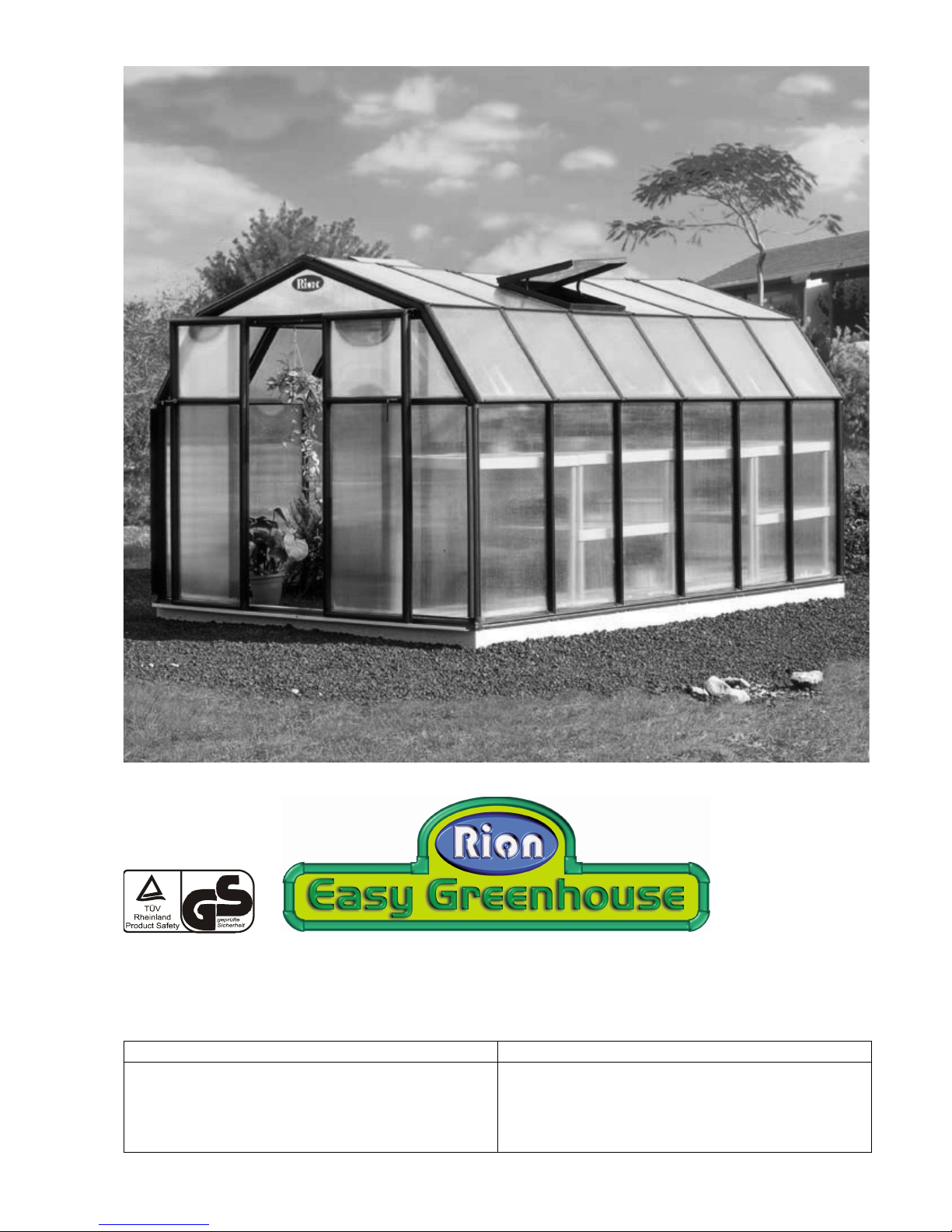
Rion GH40 User manual

Rion GH40 Greenhouse Assembly Instructions
Modular greenhouses, garden sheds, outdoor garden elements and accessories
Designed and manufactured by Rion
A Member of the Plasson Group
International Headquarters North American Distributor
Rion Ltd.
Cabri 25120 OIsrael
Tel: +972-4-995-2666, Fax: +972-4-995-2677
email: [email protected]
homepage: http:\\www.rion.com
Systems Trading Corporation
450 Seventh Ave. Suite 2803 ONew York, NY 10123
For Customer Service (Toll-Free) 877-407-9100 Ext. 1
To E-Mail: customerservice@stcaustin.com
To Send a Fax: 512-407-9242

© 2006 Rion Ltd.

1
Safety First
• Check the contents of the greenhouse packaging against the packing list and the required parts for your
model on page 4 and following. Do not begin assembly if any parts are missing.
• Please read these Assembly Instructions completely before assembly and keep them in your records so you
can refer to them if you wish to add options or make repairs.
• The instructions in this manual lead you through each step in the assembly process. It is important for you to
follow them closely.
• We recommend that you use gloves during assembly.
• Rion is not responsible for the misuse of tools or parts.
• If local building codes require permits or licenses make sure that they are acquired before beginning.
• Your Greenhouse should be securely anchored to the prepared foundation or the Modular Base (available as
an option) using the recommended hardware.
• If you prepare a concrete foundation do not excavate and pour concrete in frozen ground.
• Exercise caution when lifting heavy assemblies.
• Do not attempt to assemble your Greenhouse in high winds.
• We recommend that you place your Greenhouse in a spot where it will receive direct sunlight and will be
protected from the wind as much as possible. The door should not face prevailing winds.
• When your Greenhouse is fully assembled examine it for sharp edges and trim with a razor knife if
necessary.
• Close all roof vents in high winds.
• It is important to clear your Greenhouse of snow in the winter.
• Make sure that the temperature in the greenhouse never exceeds 70° C (155° F). Ensure good ventilation
during hot days or provide a shading screen. This is especially important if you live in a hot climate.
Required Tools
Before you start assembly have the following available:
• Measuring tape
•Spiritlevel
• Scissors
•Gloves
•Razorknife
Note: You may find some parts easier to assemble if you first moisten them with soapy water.
Concrete Foundation
• 70 mm x 6 mm (2C" x B") screws and concrete anchor set or expansion anchor. (See quantities on
page 3.)
•Hammer
• Power drill and appropriate masonry bit
• Screwdriver for screws or wrench for expansion anchors. A power tool with the appropriate bit is
recommended.
Note: If you have purchased a Modular Base all hardware is included.
Accessories
• Your Greenhouse comes with two roof vents. Additional roof vents (Part WIN33AC) are available as an
option.
• A Modular Base can be purchased for your Greenhouse’s foundation.

2GH40 Greenhouse Assembly Instructions
Introduction
Congratulations on purchasing a Rion Greenhouse. We are certain that it will give you many happy years of
pleasure in your garden.
The drawings in this manual are designed for the greenhouse owner who has purchased a GH44, which
consists of one front unit (GH40A), and one back unit (GH40B). If you have purchased additional modules the
instructions are indicated in the text.
The Greenhouse has been designed to be as easy to put together as it is beautiful to look at. Most of the work
can be done by a single person. Only attaching the roof requires the help of a family member or neighbor for a
short while.
Easy assembly methods eliminate the need
for tools or special expertise.
Connect the specified parts.
Match the holes in the profiles and the
connectors. Place a pin on the pin tool
and push the pin through the lined-up
holes to lock the parts in place. Many
connections require pins on both sides.
Note: Extra pins are included.
If you wish to disassemble the parts at
any time, remove the pins using the pin
tool. Place the end into the exposed hole
and lever the pin out.
If a hole in the connector is missing, drill
a hole with a 6 mm (¼") drill bit through
the assembled profile and then insert the
pin.
In extremely rare cases connectors will
not slip into some round or oval profiles.
In this case place the affected part into 10 cm (4") of boiling water for 15 seconds before connecting.
Note: In some models profiles have identification stickers. We recommend removing them as you work.
Greenhouse assembly is done in the following steps:
Prepare a Foundation for Your Greenhouse (page 3)
Identify Greenhouse Parts (page 4)
Prepare Your Parts for Assembly (page 7)
Lay Out the Greenhouse Frame (page 8)
Secure the Frame to the Foundation (page 9)
Assemble the Roof Pediments (page 10)
Assemble Roof Framework (page 12)
Cover the Greenhouse Roof (page 13)
Raise the Roof (page 16)
Cover the Walls (page 17)
Seal Panels (page 19)
Assemble the Doors (page 20)
Hang the Doors (page 21)
Final Touches (page 22)

3
Prepare a Foundation for Your Greenhouse
Before assembling your new Greenhouse a proper foundation must be prepared. A number of anchoring
options are possible, based on wind and ground conditions in your area. Make sure that you have checked with
your local authorities regarding any required building permits.
Decide at this time the final orientation of your Greenhouse. We recommend that you place your greenhouse
in a spot where it will receive direct sunlight and will be protected from the wind as much as possible. The door
should not face prevailing winds. It is important to clear your Greenhouse of snow in the winter.
Modular Base (Option)
If you have purchased the optional Greenhouse Modular Base follow the assembly instructions in the
packaging. The Greenhouse Modular Base can be placed in an excavated hole or on the ground. In either case
you will require sufficient gravel, earth or other suitable material to fill the base (see table below). All required
hardware is included.
Treated Wood Base
Build a framework composed of 4 ×6 () and 2 ×12 () treated
lumber using deck screws or galvanized lag bolts and fill it with
gravel or earth or other suitable material to fill the base up to the top
surface of the 4 ×6 (). Attach the greenhouse frame through the
connectors using screws that are 6 mm (B") in diameter and no less
than 70 mm (2C") long (not supplied).
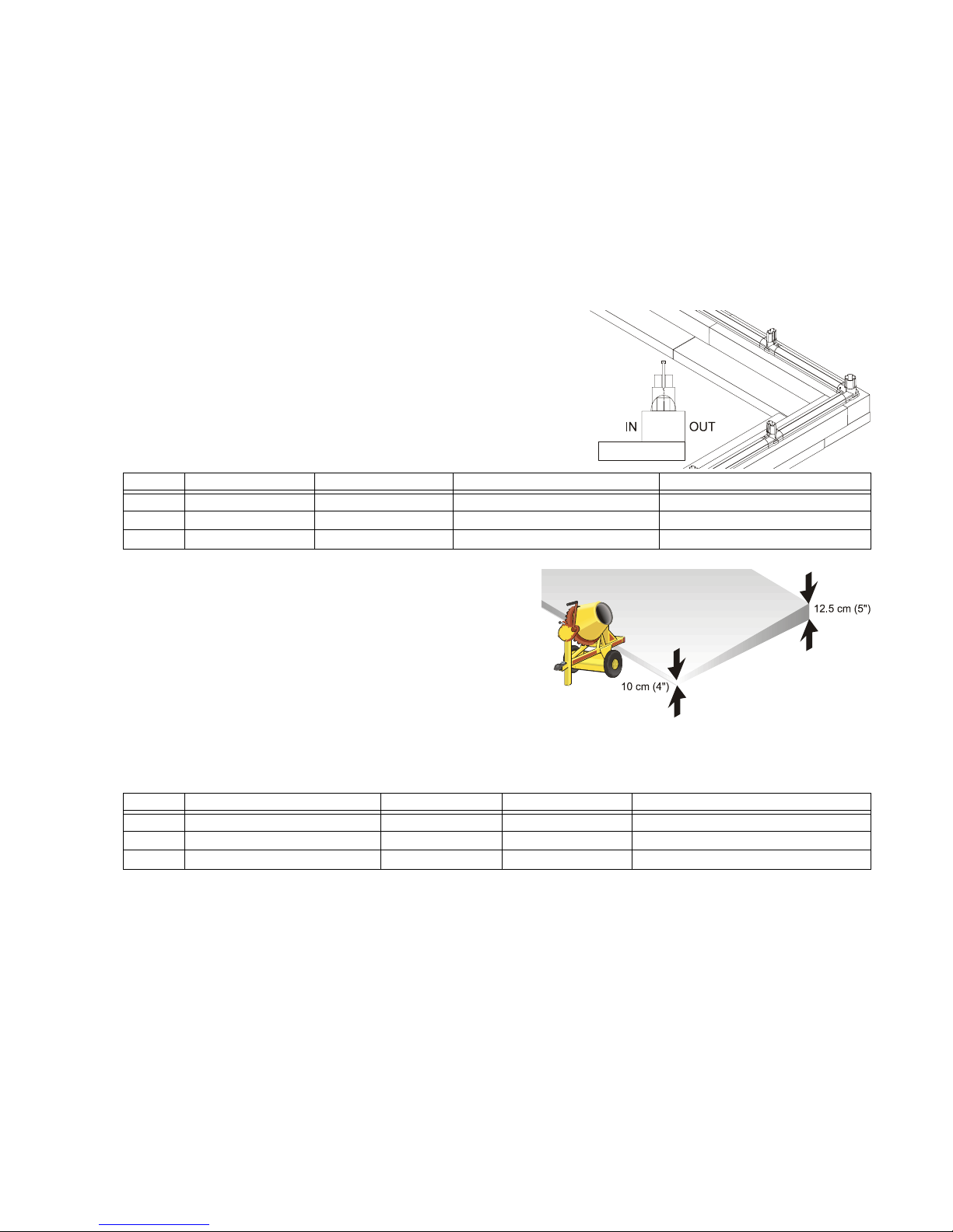
Concrete Foundation
Prepare a poured concrete foundation according to local
building codes. Do not excavate and pour concrete in frozen
ground. Make sure that there is a slight slope for drainage.
Pour your foundation according to the size of the greenhouse
model you have selected. Make sure that the foundation is at
least 10 cm (4") larger than the size of the greenhouse. The
Greenhouse is secured to the concrete foundation using
screws and concrete anchors or expansion anchors (not supplied). Use screws 6 mm (B") in diameter and no
less than 70 mm (2C") long. A drill with an appropriate masonry bit is required.
Note: You may assemble the greenhouse on its base on a hard surface and move it to its final position when
you have finished. Make sure that there are no obstructions between the assembly area and the final position.
Other Foundation Options
Wood Deck
Your Greenhouse can be secured to a wood deck with screws (not supplied) through the frame connectors. Use
screws that are 6 mm (B”) in diameter and no less than 70 mm (2C“) long. Make sure that the wood deck
itself is securely anchored to the ground. See hardware quantities and foundation measurements above.
Excavated Trench
Your Greenhouse can be placed in an excavated trench to anchor it to the ground. See the foundation
measurements above for dimensions.
Model Base Width Base Length Fill Quantity Screw/Lagbolts
GH44 2.65 meter (8’ 8J”) 2.65 meter (8’ 8J”) 0.68 cubic meters (24 cubic feet) 20
GH46 2.65 meter (8’ 8J”) 3.90 meter (12’ 9L”) 1.02 cubic meters (36 cubic feet) 28
GH48 2.65 meter (8’ 8J”) 5.14 meter (16’ 10E”) 1.36 cubic meters (48 cubic feet) 36
Model Modules Foundation Width Foundation Length Screw/anchor set or expansion anchor
GH44 GH40A++GH40B 2.70 meter (8’ 10”) 2.70 meter (8’ 10”) 20
GH46 GH40A++GH40B 2.70 meter (8’ 10”) 3.95 meter (12’ 11”) 28
GH48 GH40A++GH40B 2.70 meter (8’ 10”) 5.20 meter (17’) 36

4GH40 Greenhouse Assembly Instructions
Identify Greenhouse Parts
Because of the Greenhouse modularity, you may purchase additional GH40M modules to fit your needs.

5
Take a minute to make sure you have everything you need.
Note: Do not proceed with assembly if any parts are missing.
The part code is stamped on each connector. Profiles are listed in order by size, largest to smallest. Panels are
identified with stickers.
Exact dimensions can be found in the packing list.
The drawings in this manual are designed for the greenhouse owner who has purchased a GH44, which
consists of one front unit (GH40A), one back unit (GH40B) and . If you have purchased additional modules the
instructions are indicated in the text.
Part Code GH44 GH46 GH48 Description
01444CornerFrameConnector
2D 11 15 19 Frame Connector
15111DoorwayFrameConnector
3A222LeftRibConnector
4A222RightRibConnector
5A 15 25 35 Rib Connector
6A222LeftPedimentConnector
7A222RightPedimentConnector
8A222TopPedimentConnector
09 10 10 10 T-Oval Connector
10333OvalJunctionConnector
B2 16 20 24 Base Profile (50 cm, 1' 7M")
18
18D
4
4
4
4
4
4
Corner Oval Connector
Corner Oval Connector (Door)
Door44111UpperDoorLintel(1290 cm, 4’2C”)
PS1”/14444InnerDoorLatchScrew
Door22222BottomDoorHinge
DoorH2222InnerDoorLatch

6GH40 Greenhouse Assembly Instructions
AS80444DoorRunnerScrew/Wingnut
Door33111DoorHandle
R1444RoundProfile(113cm,3'8A")
R8444RoundProfile(80.2cm,2'7L")
R2444RoundProfile(53.4cm,1'9")
E12111OvalProfile(116.2cm,3'9C")
E1 15 19 23 Oval Profile (113 cm, 3' 8A")
E66 1014OvalProfile(85cm,2'9K")
E2 34 48 62 Oval Profile (54 cm, 1' 9B")
E18666OvalProfile(51.4cm,1'8B")
E4999OvalProfile(39.4cm,1'3A")
E5444OvalProfile(13.4cm,5B")
SR1222InnerRoundProfile(40cm,1'3C")
D1222SideCap
D2357MiddleCap
PN1141822WallPanel-(59.7×118.3 cm)
(1' 11A" ×3' 10L")
PN2 4 8 12 Lower Roof Panel - (60.5 ×66.7 cm)
(1' 11N" ×2' 2B")
PN2A444LowerRoofPanel(side)-(61.7×66.7 cm)
(2' J" ×2' 2B")
PN5L222SidePanel(Left)-(58.1×44.9 cm)
(1' 10G" ×1' 5M")
PN5R222SidePanel(Right)-(58.1×44.9 cm)
(1' 10G" ×1' 5M")
PN8R222PedimentPanelHalf(Right)
PN8L222PedimentPanelHalf(Left)
ST7444WindowCouplers
PN9222UpperBackWallPanel-(59.9×44.7 cm)
(1' 11L" ×1' 5E")
PN40 4 8 12 Top Roof Panel - (60.5 ×97.6 cm)
(1' 11N" ×3' 2E")
PN40A222TopRoofPanel(outside)
(61.7 ×97.6 cm) (2' J" ×3' 2K")
PN17222DoorPanel(top)-(57.1×45.1 cm)
(1' 10A" ×1' 5C")
PN18222DoorPanel(bottom)-(57.1×118.7 cm)
(1' 10A" ×3' 10C")
WIN33222RoofVent
WINH31222RoofVentHandles(packagesof2)
GSC10222BackPedimentStrengtheningBar
GSC12
(inside E12)
111FrontPedimentStrengtheningBar
Part Code GH44 GH46 GH48 Description

7
Prepare Your Parts for Assembly
Remove everything from your packages and sort them according to part type. Since
assembly is done from taking parts from every box, it is best to put everything together.
The boxes are printed with a ruler to help you distinguish between profiles.
Note: Protect unassembled panels from the sun to prevent identification stickers from adhering to the glazing.
DSN111DoorSealer(roll)
GF111FlexibleGlazingSeal(roll)
RA1468RAGlazingElement(57.3cm,1'10L")
RB4 6 10 14 RB Glazing Element (84.8 cm, 2' 9E")
RB6444RBGlazingElement(80cm,2'7A")
RB1101418RBGlazingElement(52cm,1'8A")
RC5101418RCGlazingElement(95.5cm,3'1F")
RC1101418RCGlazingElement(66.6cm,2'2B")
RC3468RCGlazingElement(58cm,1'10N")
RD1 16 24 32 RD Glazing Element (56.9 cm, 1' 10E")
PIN1357ConnectorPin(packages)
GT1222PinandGlazingTool
SF111SoftFoamRoofInsulation(roll)
SUPP1 357RoofReinforcementKit(Packets)
AS706 1014Cablescrew
AW5111AllenWrench
Hook1357TopCatch
CAB40357Cable
Part Code GH44 GH46 GH48 Description

8GH40 Greenhouse Assembly Instructions
Lay Out the Greenhouse Frame
Decide in which direction the door will face and place the parts on the prepared foundation or wood deck.
Note: If you are using a modular base or other foundation option (see page 3) assemble the base on a flat
surface (such as a driveway or a garage) and them move it into position when you are done.
Slide the SR1 profiles into the two B2 frame profiles that will be used for the doorway.
Place the two prepared B2 frame profiles on either side of the 15 connector.
Place a 2D connector on both sides.
Place the other parts of the frame in place and push them together. Make sure that the channel of the 2D
connectors faces outward. Each base connector is stamped with an arrow pointing to the outside direction.
Lock the frame together with pins.
Make sure that the
frame is perfectly
rectilinear by
measuring the
diagonals and
verifying that they are
the same.
Use a spirit level to
make sure that the
frame is level.

9
Secure the Frame to the Foundation
Make sure you have the proper hardware before beginning this step. (See page 3.)
Note: If you are using a modular base and filler you may assemble the greenhouse on a hard surface and move
it to its final position when you have finished. Make sure that there are no obstructions between the assembly
area and the final position.
Concrete Foundation
Mark the foundation through each connector using a scribe or screw.
Carefully move the frame and then drill holes using an appropriate masonry bit. Insert concrete anchors or
expansion anchors (not supplied) in each hole.
Move the frame back into place. Make sure that it is still perfectly rectilinear. Secure the screws/anchors in
place.
Modular Base, Wood Deck, or Treated Foundation
Insert screws into the frame connector holes and secure them to
the base.
Note: If you have purchased the Modular Base all necessary
hardware is included.

10 GH40 Greenhouse Assembly Instructions
Assemble the Roof Pediments
Put ST7 couplers on the PN8R and PN8L pediment panel halves as shown. The tops of each coupler are
trimmed to match the angle of the panel.
Note: The outside surface of the panels have special UV protection, indicated by the logo and the plastic
identification strip. Remove plastic ID strips when as panels are locked in place.
Slide the two pediment panel halves together.
Assemble all parts of the front pediment except for the 7A connector and the R8 profile. Take care that the
internal metal strengthening bar in the E12 profile remains in place.
Slide the assembled PN8R/PN8L pediment panel into the open space of the pediment.
Complete the front pediment with the 7A connector and the R8 profile, taking advantage of the flexibility of
the profiles.
Lock the pediment in place using pins and remove the ID strips from the panels.
Complete Doorway Pediment
Attach the E4R and R2 profiles to the lower right pediment. The E4R profile has a sticker indicating the up
direction.
Slide the PN5R panel
in place. Make sure
that the plastic ID
strip faces out.
Connect the 4A and
09 connectors to an
E2 profile and put it
in place taking
advantage of the
flexibility of the
profiles.
Lock the panel with
pins.
Assemble the lower
left pediment in the
same way. Note the
“UP” sticker on the
E4R profile.
Remove the ID strips
from the panels.

11
Back Pediment
Put ST7 couplers on the PN8R and PN8L pediment panel halves with the ID plastic strip facing outside. The
tops of each coupler are trimmed to match the angle of the panel. Slide the two pediment panel halves
together.
Assemble all parts of the back pediment except for the 7A connector and the R8 profile and slide the
assembled PN8R/PN8L pediment panel into the open space of the pediment. Complete the back pediment,
taking advantage of the flexibility of the profiles.
Lock the pediment in place using pins and remove the ID strips from the panels.
Slide two GSC10 strengthening bars into both sides of a 10 connector, one in the upper section and the other
in the lower section. They will overlap inside the connector and their ends will be flush with the far end.
Slide two E2 profiles over the GSC10 strengthening bars. The ends of the strengthening bars will extend
beyond the E2 profiles.
Complete the back pediment support with the 10 connectors, E2 profiles and 4A and 3A connectors as
shown.
Put the remaining profiles on the back pediment top.
Slide the back pediment panels in as shown. Make sure that the plastic ID strip faces the outside.
Note: If you have purchased one or more optional Louvered Windows insert them instead of the PN9 panels.
Put the back pediment support in place, taking advantage of the flexibility of the profiles.
Lock everything into place using pins and remove the ID strips from the panel.

12 GH40 Greenhouse Assembly Instructions
Assemble Roof Framework
Note: Assemble the roof in an area not too far away from the completed base.
First assemble the first arch.
Slip one end of the CAB40 cable through the
6 mm (¼")
channel on the underneath side of the 5A connector. You
may use the GT1 pin and glazing tool to assist you.
The cable does not go through the central hole of the
connector.
Screw an AS70 screw using the AW5 Allen wrench through the CAB40 cable and the pin holes in both sides
of the connector.
Note: The end of the screw should not extend beyond the outside channel of the E2 profile so it won’t interfere
with the placement of the RB1 glazing element (page 13).
Repeat the previous two steps for the 5A connector on the other side of the arch.
Lock the parts in place using pins.
Repeat steps through for the rest of the arches according to the number of GH40M modules you have
purchased.
Grasp the
center of each
CAB40 cable
with the Hook1
Top Catch and
slide it into the
top 5A
connector as
shown.
Add E2 profiles
to the front
pediment and
lock the parts in
place using pins.
Add E2 profiles
to the
completed ribs
according to the
number of
modules you
have purchased
and lock them
into place with
pins.
Complete the
roof by
attaching the
back pediment. Lock it into place with pins.

13
Cover the Greenhouse Roof
Step in the
framework of the
lower window to
reach the top of the
roof conveniently.
Place RA1 glazing
elements on the top
of the roof by
placing one end in
the top channel and
pushing it down
along the length of
the profile.
Place RB1,
RB4, and
RB6 glazing
elements
along the
arches
where
shown.
Place one
end of the
RB
elements in
the
channels of
the profiles
and slide
them down
the length
of the
profile.
Note: If you
have difficulty
inserting the
top of the RB1 glazing element slightly loosen the AS70 screw holding in the CAB40 cable.
Tighten the AS70 screws holding the CAB40 cables with the AW5 Allen wrench.

14 GH40 Greenhouse Assembly Instructions
Place RD1 elements
where shown by
placing one end in
the channel and
pushing it down
along the length of
the profile.
Note: You may find it
easier to insert RD
elements into profiles
by pushing them in
from the top while
rolling the element
downwards.
Note: Before the next
step decide where you
want to put the WIN33
Roof Vents. We
recommend that they be
placed in the front or back
of your greenhouse.
Place the PN40 panels
and the PN40A side
panels in place by sliding
one corner into the RD1
glazing element.
Continue until they are
fully inserted.
Remove the ID strips
from the panels.
Assemble the two
WINH31 handles to
each WIN33 Roof Vent
using the included pins.
Insert the Roof Vents by
sliding one corner into
the RD1 glazing
element. Continue until
they are fully inserted.
To install a WIN33 Roof Vent in a central position (instead of a PN40 panel) first you must trim the edges as
follows:
After assembling a WIN33 window handles trim 6 mm (¼") from
each side with a razor knife or hacksaw.
Remove the cut portion.
Note: Additional Roof Vents are available as an option.
Caution: Close windows in high winds. Automatic window
openers are available as an option.
PN40A WIN33
WINH
WINH
PN40
PN40
PN40
PN40
WIN33
PN40A
Table of contents
Other Rion Lawn And Garden Equipment manuals
Popular Lawn And Garden Equipment manuals by other brands

Greentek
Greentek MULTI-BRUSH Operator's manual

Billy Goat
Billy Goat SC120H Operating and safety instructions

Craftsman
Craftsman 842.242560 owner's manual

RedMax
RedMax AG4300 Owner's/operator's manual

Rewatec
Rewatec Modena 200 Installation & assembly instructions

Toro
Toro ProLine 139-7860 installation instructions