Rioned Andy Guest Jetters 2 Series User manual
1
2-SERIES OPERATOR’S MANUAL
OPERATOR’S MANUAL
HIGH-PRESSURE JETTING MACHINE
2-SERIES
WWW.ANDYGUESTJETTERS.CO.UK

© Copyright June 2022, Andy Guest Jetters Ltd
Unit 11, Riparian Way
The Crossings Business Park
Cross Hills
Keighley
West Yorkshire, UK
BD20 7BW
Tel: +44 (0)3300 240404
Fax: +44 (0)1535 636969
Web: www.andyguestjetters.co.uk
All rights reserved. No part of this publication may be copied or published by means of printing, photocopying,
microfilm or otherwise without the prior written consent of Andy Guest Jetters Ltd.
This restriction also serves in respect of all corresponding drawings and diagrams.
Andy Guest Jetters Ltd has the right to change components and assemblies at any time without prior or direct
correspondence with the operators. The contents of this manual may be changed without any prior warning.
This manual is to be used only for the equipment models stated.
For additional technical information or support please contact your local service agent which may be located on the
Company’s website.

TABLE OF CONTENTS
1.0 INTRODUCTION 4
2.0 FUNCTIONALITY & GENERAL SAFETY 5
2.1 Equipment methodology 5
2.2 Installation 6
2.3 Safety Icons 6
2.4 Critical Safety Features 6
2.5 Personnel Protection Equipment (PPE) 6
2.6 General Warnings 7
2.7 Making Changes and Fabricating Non OEM Components 7
2.8 Machine Warranty 7
3.0 TECHNICAL SPECIFICATIONS 8
4.0 CONSTRUCTION 9
5.0 CONTROLS 11
5.1 Before Departure 11
5.2 Positioning the Vehicle 11
5.3 Hydraulic Reel Control 11
5.4 Engine Counter 11
5.5 Run Dry Protection (Optional) 11
5.6 Pre-Operational Checks 11
5.7 Starting the Engine 12
5.8 Stopping the Engine 12
5.9 Completion Procedures 12
5.10 Operating the machine 12
5.11 Using the Radio Remote Control (Optional) 13
5.12 Nozzle Application 12
5.13 Using Lances 12
5.14 Frost Protection 14
5.15 Recommended Maintenance Schedules 15
6.0 TROUBLESHOOTING 16
6.1 Troubleshooting Guide 16
6.2 Useful Links & External References 17
7.0 SERVICE CENTRES 18
7.1 Manufacturing Sales + Service 18
7.2 Service Agents 18
8.0 APPENDIX 19
8.1 Declarations & Directives 19

42-SERIES OPERATOR’S MANUAL
Andy Guest Jetters Ltd wishes to first thank you for
your purchase of our drain and sewer-clearing
equipment. We recommend that you read this
manual thoroughly to ensure that the equipment is
maintained and operated to the highest standard.
If you require technical support, additional parts or
services or indeed would like to schedule an
approved service – please don’t hesitate in
contacting us.
The machine is built by:
Andy Guest Jetters Ltd
Unit 11, Riparian Way
The Crossings Business Park
Cross Hills
Keighley
West Yorkshire, UK
BD20 7BW
The equipment has been specifically designed and
manufactured for cleaning and unblocking
domestic and commercial drains in conjunction
with the uniquely calibrated high pressure jetting
nozzles that are supplied with your equipment (other
specialist nozzles are available for pipe cleaning,
silt removal, high fat content, other foreign material
based blockages and root cutting).
Other common uses for the equipment include the
cleaning and maintenance of walls, floors, building
materials and rubbish containers with cold or warm
water and can be used with our collection of lances
and accessories. If you aren’t sure about a particular
application you should always contact us in the first
instance for advice as no liability can be placed on
the company for consequential damage, theft or
injury to persons or property.
This manual contains all the necessary information
concerning control and maintenance. If the device is
installed correctly, properly controlled and regularly
maintained then the owner may invoke a warranty
claim for non-wear parts subject to the terms of sale
(which is normally 12 months from date of invoice
for new equipment and 3 months on second hand
purchases). Should, following our investigation it be
determined that the control and maintenance
procedures are not diligently followed, the
warranty will become invalid – this does not aect
your statutory rights.
The machine may only be used by authorised
personnel and should not be operated in an
explosive or hazardous environment. In this
manual you will find necessary information about the
operation and maintenance of your machine.
1.0 INTRODUCTION
Foreword
This operator’s manual is designed for trained and competent users of industrial jetting
equipment as prescribed by the Water Jetting Association of the United
Kingdom. The purpose of the manual is to ensure safe and ecient operation of
the equipment with any associated drawings or images to serve as a guide only.
In each section we try to familiarise users with the most important safety aspects to
consider prior to the operation of the equipment along with the operating controls and
diagnosis of potential faults.

5
2-SERIES OPERATOR’S MANUAL
2.1 Equipment Methodology
The integrated engine drives the high-pressure
pump via a gearbox system or drive belt. This pump
receives water from the water tank (which is usually
filled via the inlet reel), via the water filter before
pressurisation is applied to the desired level.
The pressurised water is ejected through the
high-pressure hose (black in colour and mounted
on the HP reel) and eventually passes through the
high-pressure jetting nozzle.
A three metre “leader hose”, normally blue in colour,
is supplied as standard with all new equipment.
When retracting a hose that is in operation, this tells
the operator that they are nearing the end of the line
and so the pump should be turned o to reduce the
risk of high pressure water being on operation
outside of the confines of the application, for
example the sewer pipe. High pressure water and
an “out of control” nozzle present one of the highest
risks to health and property when this equipment is
in use.
Most machines are derived by the type and
power of the engine – normally between
20-55 horsepower (HP).
Typically the size of engine will determine the size of
pump however these can be varied in accordance
with the two principal factors of jetter specification
– pressure (velocity of water) and flow (volume of
water). These are normally quoted in PSI (pounds per
square inch) or BAR (derived from the Greek word
baros meaning weight with 1 bar being equal to
atmospheric pressure) and Gallons or Litres per
minute – for example 3000@12 refers to 3000psi at
12 gpm and is considered one of the most common
specifications to deal with the largest volume of drain
blockages in the most ecient manner.
⊲ 1 bar is equal to 14.5 psi
⊲ 1 UK gallon is equal to 4.55 litres
There are many types of engines and pumps and
many arrangements of equipment resulting in
dierent weights, sizes, serviceability and
performance. Our equipment has been developed
over time to provide a configuration that we
believe oers a high level of performance, safety
and reliability with low ownership costs.
Whilst the financial measure of the life of our
equipment tends to be governed by customer
accounting policies, the practical life of the
machine if properly maintained can be up to 20
years depending on usage. There is a market for
used machines for which our brand of equipment
is still very desirable and as such we would always
recommend having second hand equipment that
hasn’t been refurbished by the OEM (original
equipment manufacturer) or a recognised service
agent – to be multi-point checked prior to operation.
Other common accessories for safety and
eciency include wireless remote control handset
and receiver units to turn the water on and o when
operating the jetter at a distance from the vehicle.
Remote units have the facility to start/stop water,
start/stop engine, retract the high-pressure hose reel
or provide emergency stop capabilities, depending
on the number of channels purchased and installed.
2.0 FUNCTIONALITY & GENERAL SAFETY

62-SERIES OPERATOR’S MANUAL
2.0 FUNCTIONALITY & GENERAL SAFETY
For additional protection of people or equipment,
unloader valves and run-dry switched are included
as standard on all new equipment. Unloader valves
return pressurised water back to the tank, unlike the
standard burst disc arrangement. Run dry switches
automatically stop pump operation if the machine
runs out of water.
There are also numerous optional accessories to
aid operations and safety, such as safety lances that
prevent a build-up of back pressure to the machine,
and hose guidance adapter so that operators don’t
have to come into contact with the high-pressure
hose when retracting from a sewer line.
As well as the general information in this chapter, you
should also follow the safety guidance in the other
chapters.
Always consider the safety of yourself and others
when operating this machine. Complete risk
assessments before each job to highlight potential
hazards and either avoid and/or protect people and
equipment from their consequences.
2.2 Installation
We recommend that all new machines are installed
by AG approved agents and technical teams. Third
party installation should be undertaken as per the
guidelines issued by the AG Technical Team. No
responsibility is taken for third-party installations.
2.3 Safety Icons
Any safety warnings in this manual that are
accompanied by the safety icon below (Security sign
DIN 4844-W9) are considered to present a high level
of danger to persons or equipment and should be
followed at all times.
DIN 4844-W9
2.4 Critical Safety Features
Emergency Stop
This machine is equipped with an emergency stop.
By operating the emergency stop, the machine will
stop immediately. Do not use this button for normal
operation and only use it in emergencies. The stop
button will remain depressed after application so that
the equipment cannot be restarted.
If used, and only when the danger has been
averted, twist/pull the emergency stop button back
out in order to be able to use the equipment again.
Ensure the emergency stop is always accessible.
Security Covers
This machine is equipped with several safety
covers designed to protect users from rotating parts
or hot surfaces. Do not remove these
security covers.
2.5 Personnel protection
equipment (PPE)
The following PPE is prescribed when operating the
equipment:
⊲ Ear protection (LWA 89dB)
⊲ Eye protection
⊲ Hand Protection (gloves)
⊲ Waterproof clothing
⊲ Spray boots with toe protection
Always apply PPE prior to operation of the
equipment and use your risk assessments to deter-
mine if additional PPE is required.

7
2-SERIES OPERATOR’S MANUAL
2.6 General Warnings
From our experience of commonly reported
incidents and near misses, please take note of
the following:
⊲ Never operate the equipment near a person
or animal
⊲ Use protective barriers to reduce the risk of
unauthorised access to the work area
⊲ Never block the control levers in any way or
lean equipment on or near them
⊲ Ensure that the high pressure nozzle does not
leave the drain whilst the unit is in operation
⊲ Before using a spray gun, you must always set
the pressure below the maximum (± the half of
the maximum pressure is recommended) and
this should be done before the machine
is started
⊲ Never exceed the maximum pressure that is
marked on the manometer when using the
spray gun
⊲ After use of the high-pressure circuit ensure
that you depressurise it
⊲ Always check for electrical feeds or equipment
if you are cleaning with a spray gun
⊲ Always check for loose items near the
application of the spray gun to avoid them
becoming projectiles
⊲ Personnel that use, maintain and inspect the
equipment should be suitably qualified and
authorised.
⊲ Operating the machine for sewer cleaning
means you may be exposed to bacteria and
sewer gases. Protection against contamination
is the responsibility of the operator.
⊲ Carbon Monoxide can cause severe nausea,
fainting or death. Avoid inhaling exhaust fumes.
Engine exhaust gases contain poisonous
carbon monoxide. Carbon monoxide is odour-
less, colourless, and can cause death if inhaled.
Always operate the jetting machine with the
rear doors of the van open.
⊲ Do not crank engine continuously for more
than 10 seconds. Allow a 60 second cool down
period between starting attempts. Failure to
follow these guidelines can burn out starter
motor.
⊲ If starter is engaged while flywheel is rotating,
starter pinion and flywheel ring gear may clash
resulting in damage to starter.
If the safety guidance is not observed you increase
the risk of near-misses and serious accidents.
Always try to recognise the important functions
and controls, ensure you follow maintenance and
pre-check recommendations and most importantly
remember that no job is worth risking the safety of
yourself and others.
2.7 Making Changes
and Fabricating Non
OEM Components
Changes to the machine will aect your warranty and
may result in significant rectification costs or potential
safety hazards and therefore should only be con-
ducted if authorised in writing and in advance by an
authorised representative of Andy Guest Jetters Ltd.
2.8 Machine Warranty
If the machine is set up and operated correctly and
regularly maintained, you will be covered by the
terms described in the warranty document.
If the operating and maintenance instructions are
not followed correctly, the warranty may be deemed
void and your safety and that of people in the vicinity
cannot be guaranteed.

82-SERIES OPERATOR’S MANUAL
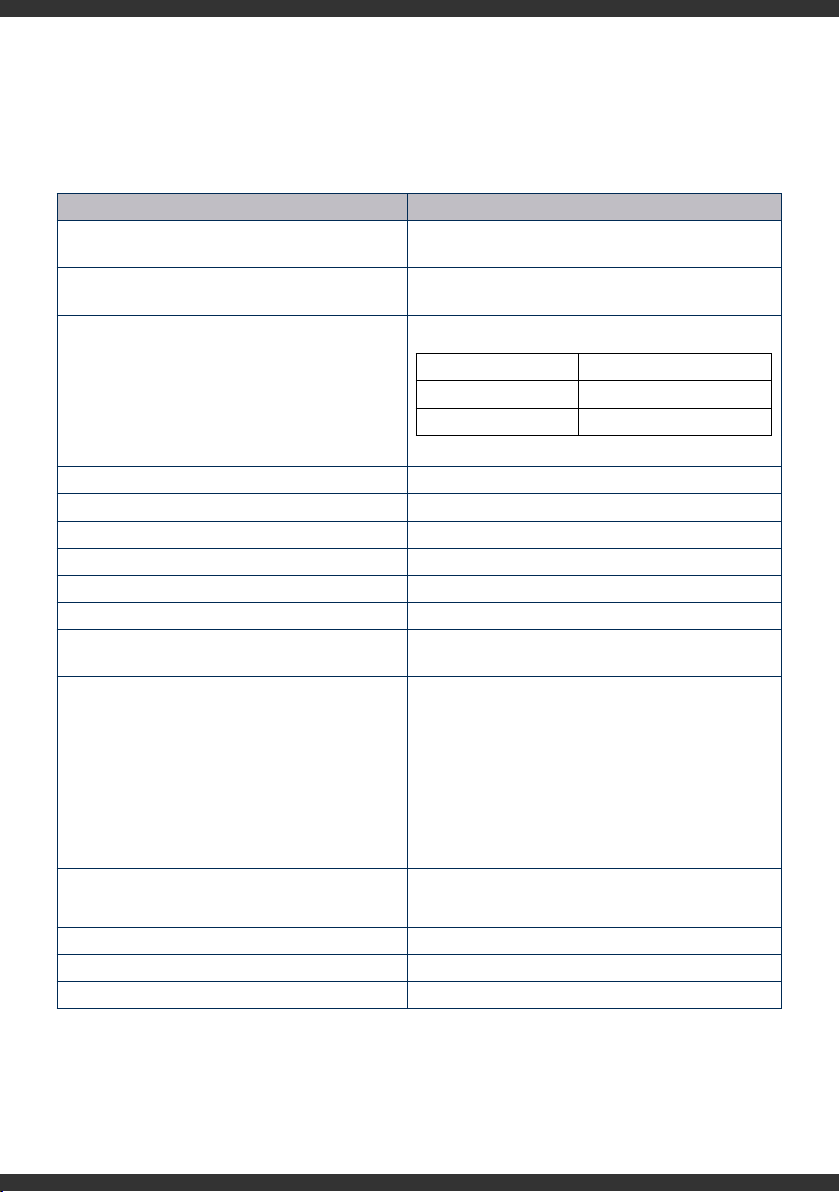
3.0 TECHNICAL SPECIFICATION
2-SERIES
www.andyguestjetters.co.uk
+44 (0)3300 240404
MADE IN UK
SERIAL No.
00-00-P000
3.1 TYPE PLATE
Every Andy Guest machines is supplied
with a Type Plate and unique serial
number, which is located in a prominent
position on the machine. When seeking
assistance with your equipment, quoting
the serial number will help us quickly
retrieve important information.
Pipework Diameter < 250mm
Performance 3000PSI @ 9GPM (200BAR @ 40LPM)
StdWater Tank Capacity 400 Litres (88 Gallon)
Engine Kubota D902 3-Cylinder Diesel Engine
HP Pump Type Triplex Plunger Pump
Engine Cooling Water-Cooled
Run Dry Protection Standard
Frost Protection Unloader & Anti-freeze Valve
HP Reel Hydraulic Drive HP Reel
Hose Guidance Not Included (Optional)
Hose Single-wire Lightweight Hose
Reel Arrangement Integrated Filling Reel
Filling Hose 25M Reel
Control Box Ye s
Remote Control Plug and Play Radio Remote
Construction Compact Mild Steel Construction & Powder Coated
Included Accessories 2 Standard Nozzles, User Manual, leader hose
Base Vehicle Suitability Ford Transit Connect, Vauxhall Combo/Vivaro, Mercedes Benz Citan,
VW Caddy/Transporter, Renault Trafic, Peugeot Expert
Warranty 12 Months (terms and conditions apply)
9
2-SERIES OPERATOR’S MANUAL
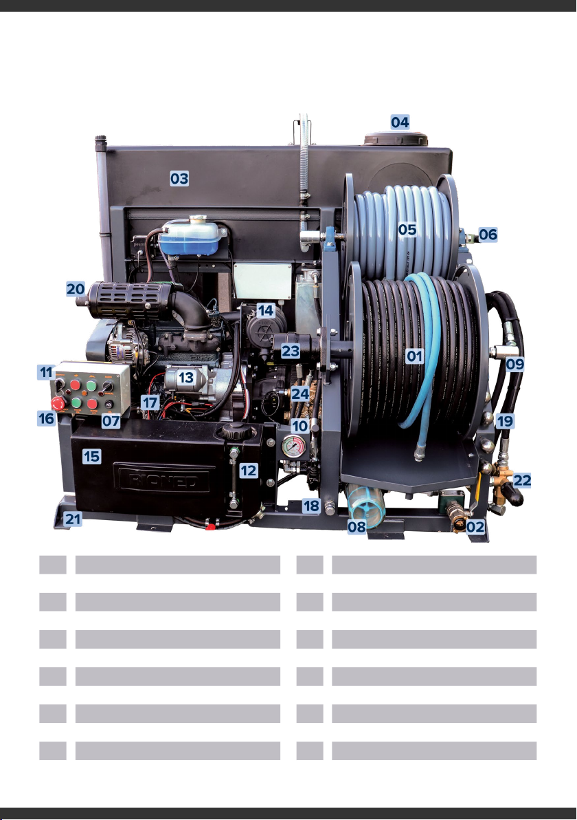
4.0 CONSTRUCTION
2-SERIES
01 High-Pressure Hose Reel 13 Kubota D902 3-Cylinder Diesel Engine
02 Drain and Anti Freeze Filling Point 14 Air Filter
03 Water Tank 15 Fuel Tank
04 Supply Opening Water Tank 16 Emergency Stop
05 Inlet Hose Reel 17 Battery
06 Inlet Hose Reel Handles 18 Engine Oil Drain
07 Control Panel 19 Nozzle Mounts
08 Water Filter 20 Exhaust Manifold
09 Rotary Joint 21 Jetter Mounts
10 Pressure Gauge and 22 Pressure Regulator
11 Ignition Key 23 Hydraulic Hose Reel Motor
12 Fuel Level Indicator 24 Triplex Plunger Pump

10 2-SERIES OPERATOR’S MANUAL
5.1 Before Departure
Before you drive away, check the following:
⊲ Roll the HP-hose neatly and fully onto the hose
reel ensuring no kinks
⊲ Roll the inlet hose neatly and fully onto the
hose reel ensuring no kinks
⊲ Ensure the water tank has been drained to
approximately 10% capacity before driving
5.2 Positioning The Vehicle
When positioning the vehicle please take note of the
following:
⊲ Vehicle engine turned o, vehicle in gear and
hand brake applied
⊲ Always try to site the vehicle on a level, hard
standing surface
⊲ See to it that the vehicle is more or less level.
⊲ If parked on a hill your fuel may run out faster
than usual if the liquid gathers away from the
suction end
⊲ Secure the working area according the local
regulations
⊲ Activate all appropriate hazard and work lights
and beacons
5.3 HP Reel Control
⊲ Always retract the hose slowly to ensure it is
neatly rolled onto the reel, keep hands and
clothing away from the reel to avoid crushing
and always check for contaminants or sharps
that may have lodged onto the reel.
⊲ It is good practice to check the condition of
the hose during retraction and if you suspect
any damage to the hose you should have it
replaced by an authorised agent immediately
5.4 Engine Counter
Some engines are equipped with a visual hours
counter. This indicates the total number of hours that
the engine has been operated and can be used to
determine when the unit is ready for
maintenance and servicing.
5.5 Run Dry Protection
Units are equipped with a run dry switch. When the
tank water level reaches approximately 5-10% the
engine will automatically turn o, furthermore an
override switch can also be added so that in the
event that the run dry switch activates, the operator
may still briefly use the engine to activate other
functions such as the hydraulic reel control or the
anti-freeze suction valve.
5.6 Pre-Operational Checks
You should check the following prior to operation:
⊲ Engine Oil
⊲ Pump Oil
⊲ Fuel Level
⊲ Gear Oil
⊲ Water Level in main tank (maximum recom-
mended water temperature is 60oc / 140of)
⊲ Water filter should be clean and free of debris
⊲ Check nozzle holes and clear debris before
attaching nozzle to the high pressure hose
⊲ Connect the inlet hose to your supply feed and
turn on OR put a supply hose directly into the
water tank by removing the filler cap
5.0 CONTROLS Note: all controls and their operation will be clearly
labelled on all new equipment.

11
2-SERIES OPERATOR’S MANUAL
5.7 Starting The Engine
To start the engine using the electronic control panel,
take the following steps:
1. Ensure you are in a position to operate the
equipment safely
2. Ensure that NO nozzles are attached to the
high-pressure hose.
3. Ensure the emergency stop button is in the
OPEN position
4. Ensure the control switch is set to MANUAL
5. Turn key switch to START position. Release
switch as soon as engine starts
6. Add your selected NOZZLE and feed the hose
into the drain
7. Press the WATER ON button
8. Use the THROTTLE buttons to increase or
decrease the water pressure
5.8 Stopping The Engine
To stop the engine please ensure the following:
1. Reduce engine speed to idle
2. Disengage HP pump fully
3. Turn fuel valve to full closed position (optional).
Turn key switch to OFF position.
5.9 Completion Procedures
At the end of the job, you should:
⊲ Remove nozzle from hose and store on frame
bracket if applicable
⊲ Retract the HP hose and secure
⊲ Retract the inlet hose and secure
⊲ Stop the engine, store any accessories and
drain the water tank down to approximately
5-10% capacity
5.10 Operating the
Equipment
The 2-Series features an Electronic Control Panel
which is easily integrated with an optional Radio
Remote system. The machine can be operated in
two ways, either directly by using the push buttons
on the Electronic Control Panel or via the Radio
Remote handset.
The Electronic Control Panel includes a built-in
throttle, HP Pump ON/OFF and Emergency Stop
button controls.
Standard Operation
1. Throttle UP/DOWN
2. HP Pump ON/OFF
3. Emergency Stop
5.0 CONTROLS: OPERATING THE MACHINE
1
32
12 2-SERIES OPERATOR’S MANUAL
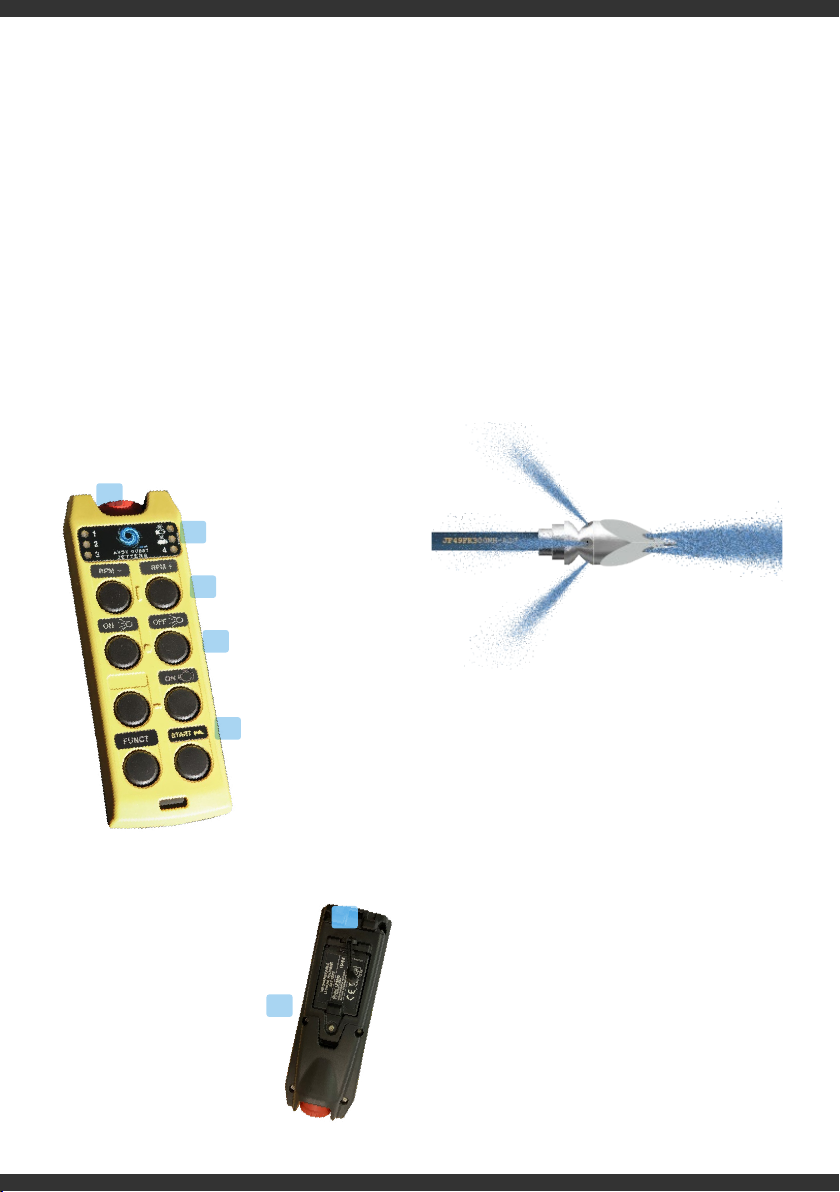
5.11 Using The Radio
Remote Control (Optional)
⊲ If no remote control is fitted switch the control
panel to manual
⊲ If you have a radio remote, ensure the switch is
set to remote
If you have purchased a radio remote control, you
should have had the receiver kit installed to your
nominated vehicle by a qualified professional and
have also received a remote handset. The AG
5-Channel provides the following operations:
Before starting the
engine, switch to “Radio
Remote” on the elec-
tronic control panel
1. Start the jetter by
pressing the START
and ENGINE buttons
simultaneously
2. Throttle UP/DOWN
3. HP Pump ON/OFF
4. Emergency Stop
5. Battery level
indicator
1. Removeable and
rechargeable lithium
battery
2. Safety cut-o strap
5.12 Nozzle Application
The high pressure nozzles are designed to use
pressure to pull the hose through the sewer pipe and
depending on application and nozzle, a degree of
cleaning or unblocking will commence immediately.
All nozzles will have the capability to eject water in
a backwards direction to project them forward and
others will also include forward ejecting water to
assist in the clearance of blockages and debris. The
basic principal can be seen below:
5.13 Using Lances
There are two types of lance:
⊲ Dry Shut
⊲ Safety or Unloader
If you are using a dry shut lance, you should
ensure that you have an unloader valve fitted to
your jetting equipment in lieu of a burst disc
arrangement. The most common cause of burst
disc failure (a manufactured weak spot to protect
from back-pressure) is when using lances. An
unloader valve (or pressure relief valve) is designed
to return water back to the water tank in the event
that the back pressure exceeds the desired level.
1
2
5
4
3
1
2
13
2-SERIES OPERATOR’S MANUAL
A safety lance or unloader lance has the valve
incorporated in its design so that any back
pressure will eject from the lance, normally through
a secondary barrel pointing in the same direction as
the pressurised water.
You should always check that the working
pressure on the lance corresponds with the pressure
of the machine and start the unit on the lowest
pressure setting and when in operation, increase
slowly to the correct working pressure. After use and
when the engine is turned o, activate the trigger to
release pressure from the hose.
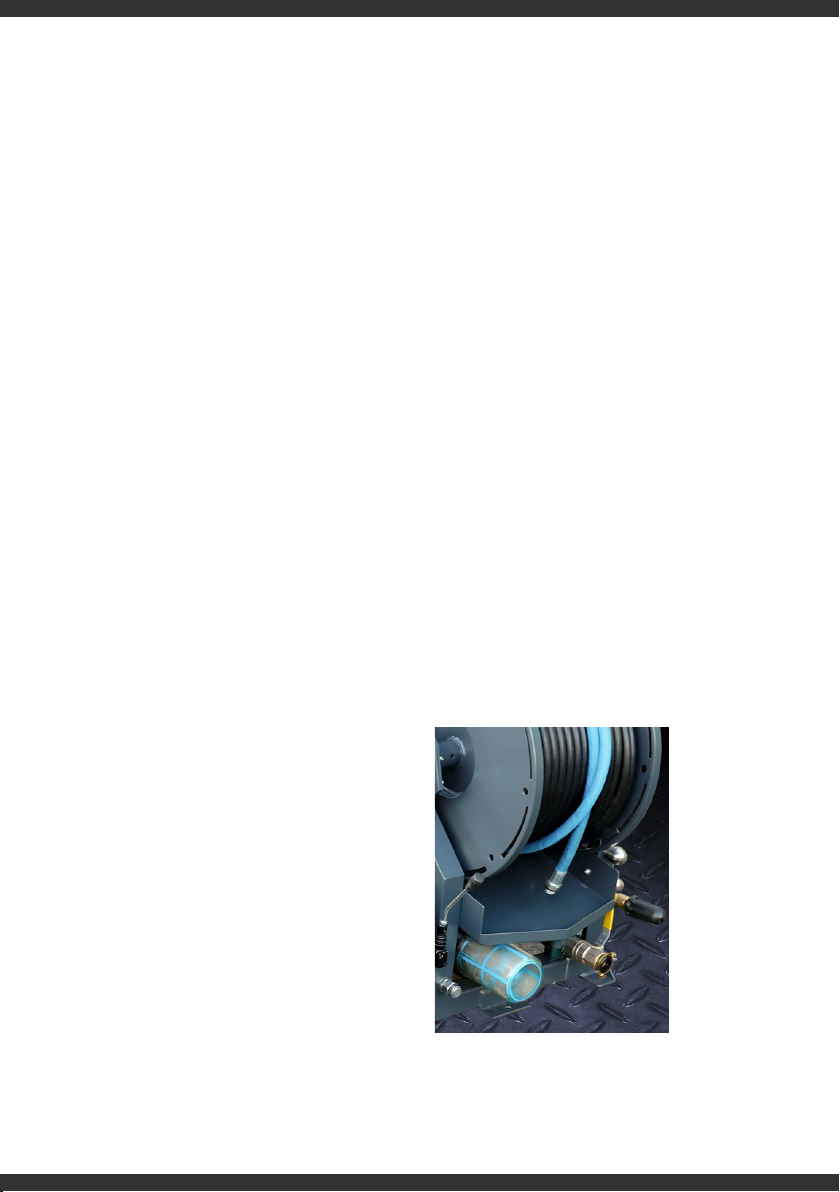
5.14 Frost Protection
It is important to protect your equipment,
particularly the high-pressure pump from freezing as
this can damage your equipment. Damaged caused
to the HP pump by frost is not covered under the
machine warranty. You should never attempt to run
your equipment if you suspect it has frozen. Many
customers will install a night heater for cold weather
periods though all equipment is fitted with an
anti-freeze valve as standard. During cold weather,
perform the anti-freeze procedure at the end of the
day or prior to any long journeys.
The following procedure should be applied:
⊲ Drain water tank
⊲ Turn anti-freeze valve to the open position
(pointing towards the anti-freeze pipe)
⊲ Turn the water tank flow valve to the closed
(vertical) position
⊲ Put anti-freeze hose into the anti-freeze drum
⊲ Turn selector valve to pressure
⊲ Start engine and run until anti-freeze comes out
of high pressure hose (ensure no nozzles are
attached)
⊲ Turn selector valve to dump and turn the
remote briefly onto pressure (remote only)
⊲ Turn remote o and stop engine
***Do not run the equipment with selector in dump
position and remote o or all anti-freeze will be
dumped back into the tank
START-UP
Post anti-freeze > pre-operation
⊲ Refill water tank
⊲ Turn anti-freeze valve and water tank flow valve
(if applicable) back to original operating position
⊲ Put pressure hose into anti-freeze drum
(ensure no nozzles are attached)
⊲ Start engine and run until water starts running
clear or drum has been filled to original level
Obviously the process will have a slight diluting
eect so care must be taken and it is only
designed to reduce the risk of freezing so normal
safety checks should always be conducted.
5.0 CONTROLS
2-Series: Valve position for filling
with anti-freeze
14 2-SERIES OPERATOR’S MANUAL
ACTION FREQUENCY
INITIAL SERVICE After first 50 hours of operation. We recommend that the first
service is through an AG approved Service Centre.
ANNUAL SERVICE We recommend that your jetting machine is serviced
annually by an AG approved Service Centre.
Check oil levels Daily. Recommended oil type usage, below.
Above 25°C (77°F) 10W-30 or 10W-40 or 15W-40
-10 to 25°C (14°F to 77°F) 10W-30 or 10W-40 or 15W-40
Below -10°C (14°F) 10W-30 or 10W-40
Recommended API classification: CF-4, CG-4, CH-4, C1,4
Clean water filter Daily or after high concentration of pollutants
Clean Engine Air Filter Every 100 working hours
Service engine Every 100 working hours or 6 monthly – whichever is soonest
Engine Oil Filter Every 200 working
Lubricate moving parts Every 250 working hours or 6 monthly – whichever is soonest
Cleaning pressure regulator Every 250 working hours or 6 monthly – whichever is soonest
Renew pump oil Every 500 working hours or every 2 years – whichever is
soonest
Check all lines (high pressure/vacuum) including fittings
for leaks.
Drain regulator of accumulated fuel deposits.
Replace spark plugs and set gap.
Have lock-o/filter serviced.
Have combustion deposits removed if using
non-synthetic oil.
Every 500 working hours or every 2 years – whichever is
soonest
Have regulator disassembled, cleaned, and reset.
Have vaporizer disassembled, cleaned, and serviced
Every 1500 working hours
Decalcify suction valves Annually
Decalcify pressure valves Annually
Re-puncture nozzle holes Every 50 working hours
Perform these procedures more frequently under severe, dusty, dirty conditions.
5.15 Recommended Maintenance Schedules
We would recommend the following maintenance plans conducted by a recognised service agent using only
OEM parts.

15
2-SERIES OPERATOR’S MANUAL
6.0 TROUBLESHOOTING
6.1 Troubleshooting Guide
Failure Reason Solution
Engine does not start or
stops abruptly
Machine has run out of fuel Add fuel
Main or secondary fuse blown Contact your service agent
Battery voltage too low Charge or replace
Emergency stop activated Release the emergency stop on machine/
remote
The high-pressure pump
does not produce the
required pressure.
Water tank empty Fill the water tank
Water tank flow valve closed Open the valve
Water filter clogged Stop the machine and clean the water filter
Air in high-pressure pump Allow the machine to run for a few minutes
and if the air doesn’t bleed out contact your
service agent
Suction valves blocked Carefully loosen the valves and descale them
Pump drive belt not suciently tightened Tighten the belt; replace if necessary
Suction valves worn out Contact your service agent
Pressure not consistent
Water level in tank too low Stop the engine, refill the tank and restart
engine
Water supply valve not suciently opened Open the supply valve completely
Water filter clogged Stop the machine and clean the filter
Pump sucks air Stop the machine and check all hoses and
couplings for leakage
Nozzle clogged Stop the machine and clean the nozzle (clean
the nozzle holes)
Pressure valves dirty or worn Stop the machine. Check the condition of the
pressure valves. Clean or replace them
Pump packing is worn out Stop the machine and replace gasket
Pump drive belts slipping Stop the machine and tighten the belts
Pump plungers damaged Contact your service agent
Pressure control clogged or damaged Contact your service agent

16 2-SERIES OPERATOR’S MANUAL
6.2 Useful Links & External References
⊲ kuk.kubota-eu.com/engines/
⊲ www.interpump.co.uk
⊲ www.waterjetting.org.uk
⊲ www.draintraderltd.com
A full range of specialist accessories and nozzles are available from the AG online store or through the parts
department. For information about Andy Guest products, services, parts and accessories visit:
⊲ www.andyguestjetters.co.uk
⊲ Call: +44 (0)3300 240404
Failure Reason Solution
Hydraulic reel does not
wind the hose
Handle not on correct position Put the handle into the correct position
Hydraulic tank almost empty Refill the tank. Check the system for leaks
Working pressure set too low Increase the working pressure, if possible
Return filter for hydraulic tank dirty Switch o the machine and clean the return
filter
Hydraulic system damaged Contact your service agent
Warning lights after short
operation Battery flat / defective
Recharge or replace battery
Check if the unit is charging correctly
Check battery terminals for debris
Electrical supply appears
fine but equipment not
functioning
Emergency stop pushed in Unlock emergency stop
Receiver has no current Check / replace fuses
No radio connection Check functions of control lights

17
2-SERIES OPERATOR’S MANUAL
7.0 SERVICE CENTRES
7.1 Manufacturing Sales + Service
7.2 Service Agents
7.3 Worldwide Agents
We have agents in many countries. Further information on our worldwide
agent network can be found on the website: www.andyguestjetters.co.uk
Andy Guest Jetters Ltd
Unit 11, Riparian Way
The Crossings Business Park
Cross Hills, Keighley
West Yorkshire BD20 7BW
T +44 (0)3300 240404
F +44 (0)1535 636969
www.andyguestjetters.co.uk
Rioned UK Ltd
FreeFlow House
Stephenson Way
Thetford, Norfolk, IP24 3RU
United Kingdom
T +44 (0)3300 240404
F +44 (0) 1638 716863
www.rioned.co.uk
Crumlin Plant Sales Limited
90a Blackisland Road
Craigavon
Portadown BT62 1NH
Tel: 0283 885 2540
HP Pump Services
Wynford Industrial Park
Romsey
Hampshire, SO51 0PW
01794 367 477
Hydro Power UK Ltd
Unit 19d Robell Way
Water Lane Industrial Estate
Storrington (Nr. Pulborough)
West Sussex RH20 3DW
Tel: 01903 741780
Kensway Engineering
Unit 5 Dotton Farm
Sidmouth
Devon EX10 0JY
Tel: 0139 556 7374
Midland Jetting Services Ltd
Unit 4 Kingfisher Ind Estate
Charles Street
West Bromwich
West Midlands B70 0AT
Tel: 0121 520 6641
N1 Jetting Systems Limited
Unit 13 Cathedral Park
Durham DH1 1TF
Tel: 0191 375 7779
Scotjet Limited
50 Loanbank Quadrant
Glasgow
Lanarkshire G51 3HZ
Tel: 0141 440 0200
Technical Camera Services
Drumnacarta, Snugboro
Castlebar, Co. Mayo F23 KW90
Tel: +353 871627963

18 2-SERIES OPERATOR’S MANUAL
8.1 Declarations & Directives
EC Declaration of Conformity for Machinery
(Directive 2006/42/EC, Annex II, sub A) Andy Guest Jetters Ltd
Unit 11, Riparian Way
The Crossings Business Park
Cross Hills
Keighley
West Yorkshire, UK
BD20 7BW
Herewith declares that:
High pressure device model AG 2-SERIES is
⊲ in compliance with the Machinery Directive (2006/42/EC);
⊲ in conformity with the provisions of the following other EEC directives: 2004/108/EC
⊲ and the following harmonised standards have been applied:
NEN-EN-ISO 12100-1, NEN-EN-ISO 12100-2, NEN-EN-ISO 13850,
NEN-EN-ISO 13857, NEN-EN-349, EN 60204-1
Jan Pieters
Managing Director
On Behalf of:
Rioned UK Ltd & Andy Guest Jetters Ltd
8.0 APPENDIX
Jan Pieters

19
2-SERIES OPERATOR’S MANUAL

20 2-SERIES OPERATOR’S MANUAL
www.andyguestjetters.co.uk
Manufacturing
Sales + Service
Service Agents
Andy Guest Jetters Ltd
Unit 11, Riparian Way
The Crossings Business Park
Cross Hills, Keighley
West Yorkshire BD20 7BW
T +44 (0)3300 240404
F +44 (0)1535 636969
www.andyguestjetters.co.uk
Rioned UK Ltd
FreeFlow House
Stephenson Way, Thetford
Norfolk, IP24 3RU
United Kingdom
T +44 (0)3300 240404
F +44 (0) 1638 716863
www.rioned.co.uk
Crumlin Plant Sales Limited
90a Blackisland Road
Craigavon
Portadown BT62 1NH
Tel: 0283 885 2540
HP Pump Services
Wynford Industrial Park
Romsey
Hampshire, SO51 0PW
01794 367 477
Hydro Power UK Ltd
Unit 19d Robell Way
Water Lane Industrial Estate
Storrington (Nr. Pulborough)
West Sussex RH20 3DW
Tel: 01903 741780
Kensway Engineering
Unit 5 Dotton Farm
Sidmouth
Devon EX10 0JY
Tel: 0139 556 7374
Midland Jetting Services Ltd
Unit 4 Kingfisher Ind Estate
Charles Street
West Bromwich
West Midlands B70 0AT
Tel: 0121 520 6641
N1 Jetting Systems Limited
Unit 13 Cathedral Park
Durham DH1 1TF
Tel: 0191 375 7779
Scotjet Limited
50 Loanbank Quadrant
Glasgow
Lanarkshire G51 3HZ
Tel: 0141 440 0200
Technical Camera Services
Drumnacarta, Snugboro
Castlebar, Co. Mayo F23 KW90
Tel: +353 871627963
Table of contents
Other Rioned Industrial Equipment manuals

Popular Industrial Equipment manuals by other brands

ABB
ABB HT587908 Operation manual

Siemens
Siemens 8GK6430 - 4KK24 operating instructions

SMC Networks
SMC Networks MGP-XB24 Mounting instructions

Dando
Dando TERRIER Mk 1 Operating and maintenance manual

Greemman
Greemman RECO130F Manual book

thermital
thermital COROLLA PACK 1000 Series Installation, operation and maintenance manual


