RSP STC20 Instruction Manual

Installation and Maintenance
Manual
Swivel tool changers STC20–STC350
M0412-1
Tool changers | Swivels | Swivels Tool changers | Grippers | Hose packages | Valve Units | Tool systems

2 M0412-1 ver 3.0

M0412-1 ver 3.0 3
The information in this document is subject to change without prior notice and should not be
regarded as an undertaking from Robot System Products AB. Robot System Products AB
assumes no responsibility for errors that may occur in this document.
Robot System Products AB bears no responsibility for damage that is incurred by the use of this
document, or the software or hardware described in this document.
The document, or parts of it, may not be reproduced or copied without prior permission from
Robot System Products AB. It may neither be imparted to a third party, nor otherwise be used
without authorization. Infringement hereof will be subject to action in accordance with the
applicable laws.
Further copies of this document can be obtained from Robot System Products AB at
current prices.
© Robot System Products AB
Robot Systems Products AB
Isolatorvägen 4
SE–721 37 Västerås
Sweden

4 M0412-1 ver 3.0
CONTENTS
1 INTRODUCTION......................................................................................................5
1.1 Installation and Maintenance manual .........................................................................5
1.2 Safety.........................................................................................................................6
1.2.1 General...............................................................................................................................6
1.2.2 Explanation of warnings .....................................................................................................6
1.3 Tightening torques......................................................................................................7
1.4 Recommended equipment .........................................................................................7
1.5 Required products......................................................................................................7
2 INSTALLATION.......................................................................................................8
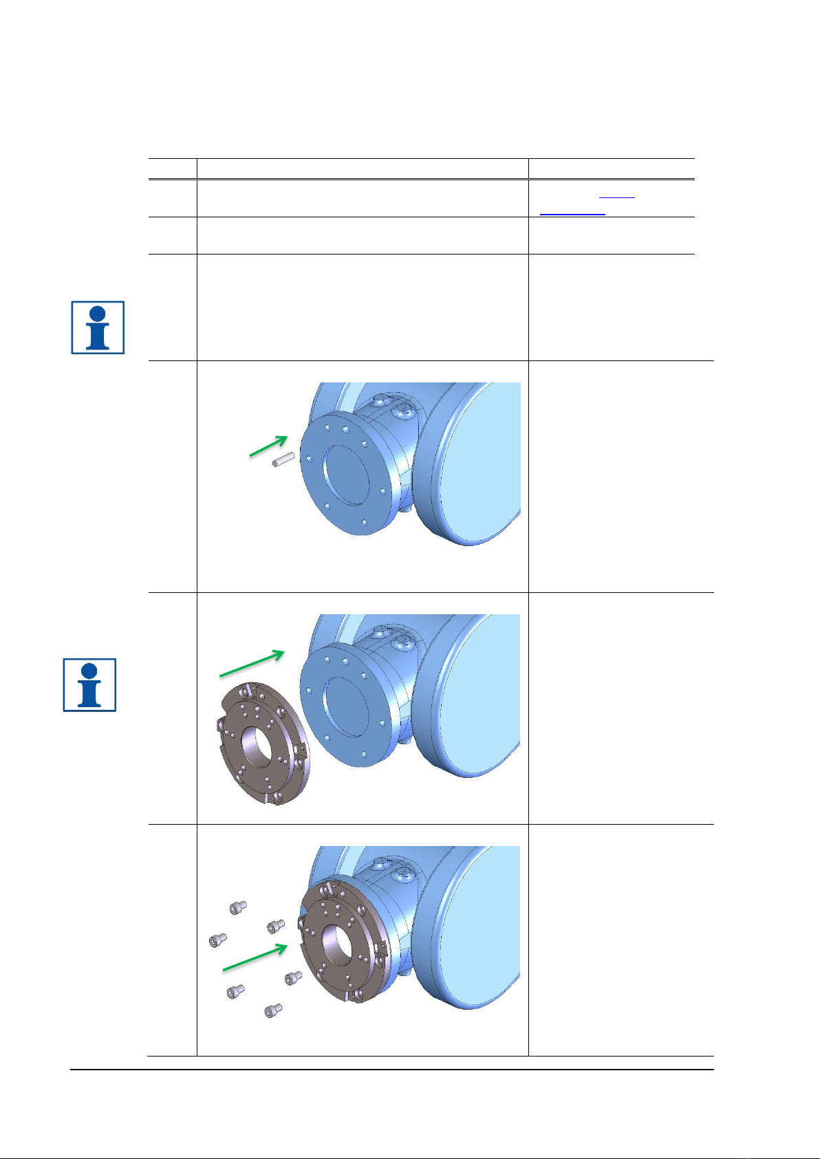
2.1 Installation of swivel tool changer on robot.................................................................8
2.2 Installation of tool attachment on tool .......................................................................11
2.3 Manual unlocking of swivel tool changer ..................................................................13
3 MAINTENANCE AND SERVICE............................................................................14
3.3 Maintenance scheme ...............................................................................................14
3.3.1 Every second week ..........................................................................................................14
3.3.2 Every six-months or 250,000 tool changes......................................................................14
3.3.3 To replace when damaged or worn-out ...........................................................................15
3.3.4 Complete service of swivel tool changer..........................................................................15
3.4 Specification of maintenance activities.....................................................................16
3.4.1 Visual inspection of swivel tool changer...........................................................................16
3.4.2 Visual inspection and cleaning of tool attachment ...........................................................17
3.4.3 Cleaning and lubrication of swivel tool changer...............................................................18
3.4.4 Cleaning and lubrication of tool attachment.....................................................................19
4 DISMOUNTING AND REPLACEMENT.................................................................20
4.1 Replacement of swivel tool changer.........................................................................20
4.2 Replacement of tool attachment...............................................................................22
4.3 Replacement of wear parts.......................................................................................23
4.3.1 Replacement of air sealings.............................................................................................23
4.3.2 Replacement of signal pins ..............................................................................................24
4.3.3 Replacement of O-ring .....................................................................................................25
5 DISPOSAL AND RECYCLING ..............................................................................26

M0412-1 ver 3.0 5
1 INTRODUCTION
Robot System Products is a front-rank provider of peripheral products for high performance
robot applications. We provide complete tool systems solutions for your robot installations,
aiming to improve your productivity with the most reliable and cost-effective tooling on the
market. Continuously we explore emerging technologies, working with leading edge design.
Robot System Products has a wide range of standard robot peripheral products:
•Tool changers
•Swivels
•Swivel tool changers
•CiRo
•Grippers
•Hose Packages
•Valve units
•Tool systems
•Tool parking systems
Robot System Products’ tool changers are constructed to maximize the flexibility and reliability
of your robot fleet. Through our patented locking device TrueConnect™ robustness and high
safety are combined with low weight and compactness. With our swivels compressed air, water,
electrical and data signals as well as weld and servo power are transferred to your tools with
robot motion capabilities fully maintained. Our Swivel tool changers unite the TrueConnect™
mechanism with our swivel technology, combining the best out of the two technologies. With
RSPs unique Circular Rotators cables and hoses can be freely selected with high robot flexibility
maintained, and the space requirements reduced. Our integrated Tool systems are delivered as
complete plug-and-play solutions designed for quick and simple installation.
Robot System Products’product lines are available for all major robot brands and come with
complete documentation. 3D-models for simulation are available for download at:
www.rsp.eu.com
1.1 Installation and Maintenance manual
This document describes how the swivel tool changers, STC20, STC100, STC250 and STC350,
including corresponding tool attachments and options for transfer of power, signals and air are
installed and replaced. In addition, the document describes required maintenance activities,
including inspection, cleaning, lubrication, replacement of wear parts, required tools and
products and disposal and recycling.
The Product Descriptions of each respective unit are separate documents containing product
information, drawings, technical data, electrical and pneumatic diagrams and lists of spare parts.

6 M0412-1 ver 3.0
1.2 Safety
1.2.1 General
The integrator installing the swivel tool changer into the system must follow the safety demands
stated in standards and provisions applicable in the country where the swivel tool changer
system is to be installed. The products are all prepared for CE-certification.
The user of the Robot System Products swivel tool changer is responsible that law and
directives applicable in respective countries, with regards to safety, are followed. The user is
also responsible to guarantee that all safety devices are installed correctly.
WARNING!
Never carry out service work on a robot that has not been taken out of operation.
See safety information for the robot.
WARNING!
Only perform work on tools attached to the swivel tool changer if the air pressure is
safely switched off.
WARNING!
Be aware that swivel tool changers and tool attachments are heavy and may cause
personal injury and equipment damage if dropped.
NOTE!
The swivel tool changer shall always be in locked position, also when empty, to avoid
unexpected locking if air pressure is lost.
WARNING!
Electric signals and power must be disconnected/switched off when docking the tool
attachment. This is to prevent sparking between signal pins and tool attachment.
1.2.2 Explanation of warnings
The warnings in this document are specific to the products in this manual. It is expected that the
user also pay attention to certain notifications from the robot manufacturer and/or the
manufacturers of other components used in the installation.
WARNING!
The warning sign will make you aware that a situation could result in potential
serious injury or damage to equipment.
NOTE!
The note sign will alert you about something important to consider.

M0412-1 ver 3.0 7
1.3 Tightening torques
Tightening torques for mounting (screw class 8.8)
Dimension
Torque
M4
3 Nm
M5
6 Nm
M6
10 Nm
M8
24 Nm
M10
47 Nm
M12
82 Nm
M16
200 Nm
1.4 Recommended equipment
Equipment recommended for installation and maintenance work
Tools
Applications
Complete set of Allen keys
For dismounting and mounting
Torx key
For all socket head cap screws
Plastic mallet
For mounting of air sealings
Pair of pliers
For dismounting the signal pins
Screw driver
For removing the air sealings
Torque wrench
For dismounting and mounting
1.5 Required products
Product
Specification
Note
Grease, 3HXG1000-413
Magnalube-G, Teflon grease
Air sealings and O-rings.
Grease I0876
Molykote BR2Plus
For locking balls.
Cleaning agent
Industrial alcohol or similar
For cleaning of tool changer and tool
attachment.
Cloth
Lint free cloth
For cleaning.
NOTE! Chemical resistance protective gloves are recommended when using grease
or cleaning agents such as industrial alcohol. Safety goggles are recommended
when working with cleaning agents such as industrial alcohol. Adequate ventilation
should be provided when chemical substances are used.

8 M0412-1 ver 3.0
2 INSTALLATION
2.1 Installation of swivel tool changer on robot
Action
Note
1
Safety
Read the safety
section 1.2.
2
Service position
Place the robot in
service position.
3
Power off
Switch the power off
and lock the circuit
breaker.
NOTE! Read the
safety chapter for the
robot.
4
Mount guide pin
Press the enclosed guide
pin into the robot flange.
5
Fit adaptation plate
Lift the adaptation plate
and fit the guide pin to the
guide hole in robot flange.
NOTE! Only if adaptation
plate is used.
6
Mount adaptation plate
Mount the adaptation
plate with the enclosed
screws. Use a torque
wrench when tightening
(see tightening torques
above).

M0412-1 ver 3.0 9
7
Fit the swivel tool changer to robot
Lift the swivel tool
changer to the robot
flange (or adaptation
plate). Make sure that
the guide pin fits to the
guide hole in the swivel
tool changer.
WARNING! The swivel
tool changer is heavy
and may cause
damage if dropped.
8
Mount swivel tool changer
Mount the swivel tool
changer with the
enclosed screws. Use
a torque wrench when
tightening (see
tightening torques
above).
NOTE! Some rotation
stops should be
mounted on the STC
before it is mounted on
the robot.
9
Turn robot arm into position
Rotate axis 6 to put the
rotation stop in position
for mounting.
10A
Mount rotation stops (STC20 and STC100)
Mount the rotation
stops with enclosed
screws and nuts. The
tightening torque for
STC20 is 4 Nm, and for
STC100 it is 6 Nm.
NOTE! Design and
mounting methods are
dependent on STC and
robot models.
NOTE! Mounting
instructions are
included in the
adaptation kits.

10 M0412-1 ver 3.0
10B
Mount rotation stops (STC250 and STC350)
Mount the rotation
stops with enclosed
screws and nuts. The
tightening torque for
STC250 and STC350 is
10 Nm.
NOTE! Design and
mounting methods are
dependent on STC and
robot models.
NOTE! Mounting
instructions are
included in in the
adaptation kits.
11
Connect air
Mount air hoses using
hose fittings.
Pneumatic diagrams
are found in the
Product Description of
respective unit.
12
Connect signals (electrical versions only)
Connect electrical
connectors in
accordance with
selected unit.
Circuit diagrams are
found in the Product
Description of
respective unit.
13
Power on
Unlock the circuit breaker
and switch the power on.

M0412-1 ver 3.0 11
2.2 Installation of tool attachment on tool
Action
Note
1
Safety
Read the safety
section 1.2.
2
Mount guide pins
Press guide pins, as
applicable, into the
corresponding holes
on the tool.
3
Fit tool attachment
Fit the tool attachment
and tool to each other
using the guide pins.
WARNING! The tool
attachment is heavy
and may cause
personal injury and
equipment damage if
dropped.
4
Mount tool attachment
Mount the tool
attachment using a
torque wrench.
NOTE! Fastening
screws can be entered
either from the tool
attachment side or the
tool side. See the
Product Description of
respective unit for
details.

12 M0412-1 ver 3.0
5
Connect air hoses
Connect air hoses
to the tool
attachment.
Pneumatic
diagrams are found
in the Product
Description of
respective unit.
6
Connect signals (electrical versions only)
Connect electrical
connectors in
accordance with
selected unit.
Circuit diagrams
are found in the
Product Description
of respective unit.

M0412-1 ver 3.0 13
2.3 Manual unlocking of swivel tool changer
Action
Note
1
Safety
Read the safety section 1.2.
2
Park the tool
Park the tool on a tool stand or table.
NOTE! Make sure that the tool attachment
and tool are fully supported by a tool stand
or table.
3
Service position
Place the robot in service position.
4
Pneumatic air off
NOTE! The pressure in the pneumatic
system must be released before
dismounting begins.
5
Power off
Switch power off and lock the circuit
breaker.
NOTE! Read the safety chapter for the
robot.
6
Release air
Release air at connections marked OPEN
and CLOSE.
Pneumatic diagrams are found in the
Product Description of respective unit.
NOTE! The open and close connections
may have alternative markings.
7
Release tool attachment
Connect compressed air to the air
connection marked OPEN. Exhaust air is
evacuated via connection marked CLOSE.

14 M0412-1 ver 3.0
3 MAINTENANCE AND SERVICE
The swivel tool changers and the tool attachments must be maintained regularly to ensure
proper function. The specified intervals are approximate and valid under normal conditions,
corresponding to 2 tool changes per minute during 2 work shifts per working day, i.e. 42.000 tool
changes per month. Under extreme conditions, such as dirty environments or extreme robot
movements, the intervals should be shortened. Consider the table as a guide and update as
your production experience of each system increases.
NOTE!
Read the safety section 1.2.before any maintenance activities are carried out.
NOTE!
Swivel tool changers must only be dismantled and repaired by Robot System
Products during the warranty period. Otherwise the warranty will not be valid.
3.3 Maintenance scheme
3.3.1 Every second week
The following maintenance activities should be carried out every second week.
Activity
Equipment
Description
Inspection
Swivel tool
changer
General
Visual inspection of swivel tool changer,
rotation stop and cables (section 3.4.1).
Looking balls
Check locking balls (section 3.4.1).
Air sealings
Check air sealings (section 3.4.1).
Spring-loaded pins
Check spring-loaded signal pins (section
3.4.1).
Tool attachment
General
Visual inspection of tool attachment and
cables (section 3.4.2).
Cleaning
Tool attachment
Signal contacts
Clean contact surfaces (section 3.4.2).
3.3.2 Every six-months or 250,000 tool changes
The following maintenance activities should be carried out every six-months or 250,000 tool changes.
Activity
Equipment
Description
Cleaning
and
lubrication
Swivel tool
changer
Looking balls
Clean locking balls and add new
lubrication, (section 3.4.3).
Air sealings
Clean air sealings (section 3.4.3).
Spring-loaded pins
(electrical versions
only)
Clean spring-loaded signal pins (section
3.4.3).
Tool attachment
Locking cavities
Clean the cavities of the locking balls.
(section 3.4.4).
Contact surfaces
Clean the contact surfaces of air
sealings (section 3.4.4).

M0412-1 ver 3.0 15
3.3.3 To replace when damaged or worn-out
Equipment
Description
Swivel tool changer
Air sealings
See section 4.3.1.
Spring-loaded signal pins
(electrical versions only)
See section 4.3.2.
O-ring around the ball holder
See section 4.3.3.
3.3.4 Complete service of swivel tool changer
Under normal working conditions we recommend a complete service on swivel tool changers to
be carried out every 30th months by qualified RSP personnel. This will ensure proper function
and increase the lifespan of the swivel tool changers considerably. Please contact us for a
quotation.
The 30 months swivel tool changers service at Robot System Products includes inspection and
cleaning of the full unit, replacement of all wear parts including sealings, signal pins and the O-
ring on the ball holder.

16 M0412-1 ver 3.0
3.4 Specification of maintenance activities
3.4.1 Visual inspection of swivel tool changer
The following maintenance activities should be carried out on the STC every 2nd week.
Action
Note
Check locking balls
Check each ball to make sure it
moves freely. For cleaning and
lubrication of balls see section
3.4.3.
NOTE! If balls get stuck there is a
risk that the tool attachment jams.
WARNING! Risk of getting
squeezed between piston and ball
holder when the piston is taking
closed position
Check air sealings
Check that the air sealings are
clean. For cleaning see section
3.4.3.
Check that the air sealings are not
damaged. For making replacements
see section 4.3.1.
Check spring-loaded signal pins (electrical
versions only)
Check that the spring-loaded signal
pins are clean. For cleaning see
section 3.4.3.
Check that the spring-loaded signal
pins are not worn-out or damaged.
For making replacements see
section 4.3.2.
Check cables and hoses
Check cables and hoses for
damages and squeezing, replace if
damaged.
Check rotation stops
Check that the rotation stops are
not worn-out or damaged, replace if
damaged.
Check swivel tool changer in general
Check the swivel tool changer for
damages. For replacement see
section 4.1.

M0412-1 ver 3.0 17
3.4.2 Visual inspection and cleaning of tool attachment
The following maintenance activities should be carried out on the TA every 2nd week.
Action
Note
Clean contact surfaces (electrical versions only)
Wipe the contact surface
with a lint free cloth.
Check cables and hoses
for damages and
squeezing, replace if
damaged.
Check tool attachment in general
Check the tool
attachment for damages.
For replacement see
section 4.2.

18 M0412-1 ver 3.0
3.4.3 Cleaning and lubrication of swivel tool changer
The following maintenance activities should be carried out on the STC every 6th month or
after 250,000 tool changes, whichever comes first.
Action
Note
Clean locking balls
Check the looking balls
and wipe them clean with
a lint free cloth.
WARNING! Risk of getting
squeezed between piston
and ball holder when the
piston is taking closed
position
Lubricate looking balls
Apply a small amount of
grease (Molykote
BR2Plus) on the locking
balls.
NOTE! It is important that
this is done or else there is
a risk that the tool
attachment jams.
Clean air sealings
Wipe air sealings clean
with a lint free cloth.

M0412-1 ver 3.0 19
Clean spring-loaded signal pins (electrical versions
only)
Clean the contact surfaces
of the spring-loaded signal
pins with a nylon brush.
NOTE!
Signal pins shall be
cleaned whenever
blackened.
3.4.4 Cleaning and lubrication of tool attachment
The following maintenance activities should be carried out on the TA every 6th month or
after 250,000 tool changes, whichever comes first.
Action
Note
Clean locking cavities
Clean the cavities of the
locking balls with a lint free
cloth.
NOTE!
It is important that this is
done or else there is a risk
that the tool attachment
jams.
Clean contact surfaces of air sealings
Wipe the contact surfaces
of the air sealings clean
with a lint free cloth.

20 M0412-1 ver 3.0
4 DISMOUNTING AND REPLACEMENT
4.1 Replacement of swivel tool changer
Action
Note
1
Safety
Read the safety section 1.2.
2
Dismount tool
Leave tool, with tool
attachment mounted, in tool
stand.
3
Service position
Place the robot in service
position.
NOTE! The tool change
function shall be in locked
position.
4
Power off
Switch the power off and lock
the circuit breaker.
NOTE! Read the safety
chapter for the robot.
5
Pneumatic air off
NOTE! The pressure in the
pneumatic system must be
released before dismounting
begins.
6
Disconnect signals (electrical versions only)
Disconnect electrical
connectors.
NOTE! Handle the
connectors with care, they
are sensitive to mechanical
damage. Make sure no dirt
enters the connectors.
6
Dismount air hoses
Put markings on the air
hoses in order to simplify
remounting. Dismount the
hoses from the swivel tool
changer.
NOTE! Make sure that no dirt
enters the air hoses.
Other manuals for STC20
1
This manual suits for next models
17
Table of contents
Other RSP Industrial Equipment manuals