P/N 960-000169R_Rev. A {EDP #217859} © 2012, Japan CashMachine Co., Limited
VEGA-RC Twin™ Series Banknote Recycler Integration Guide
Model Descriptions
Table 1 lists the product model number
descriptions.
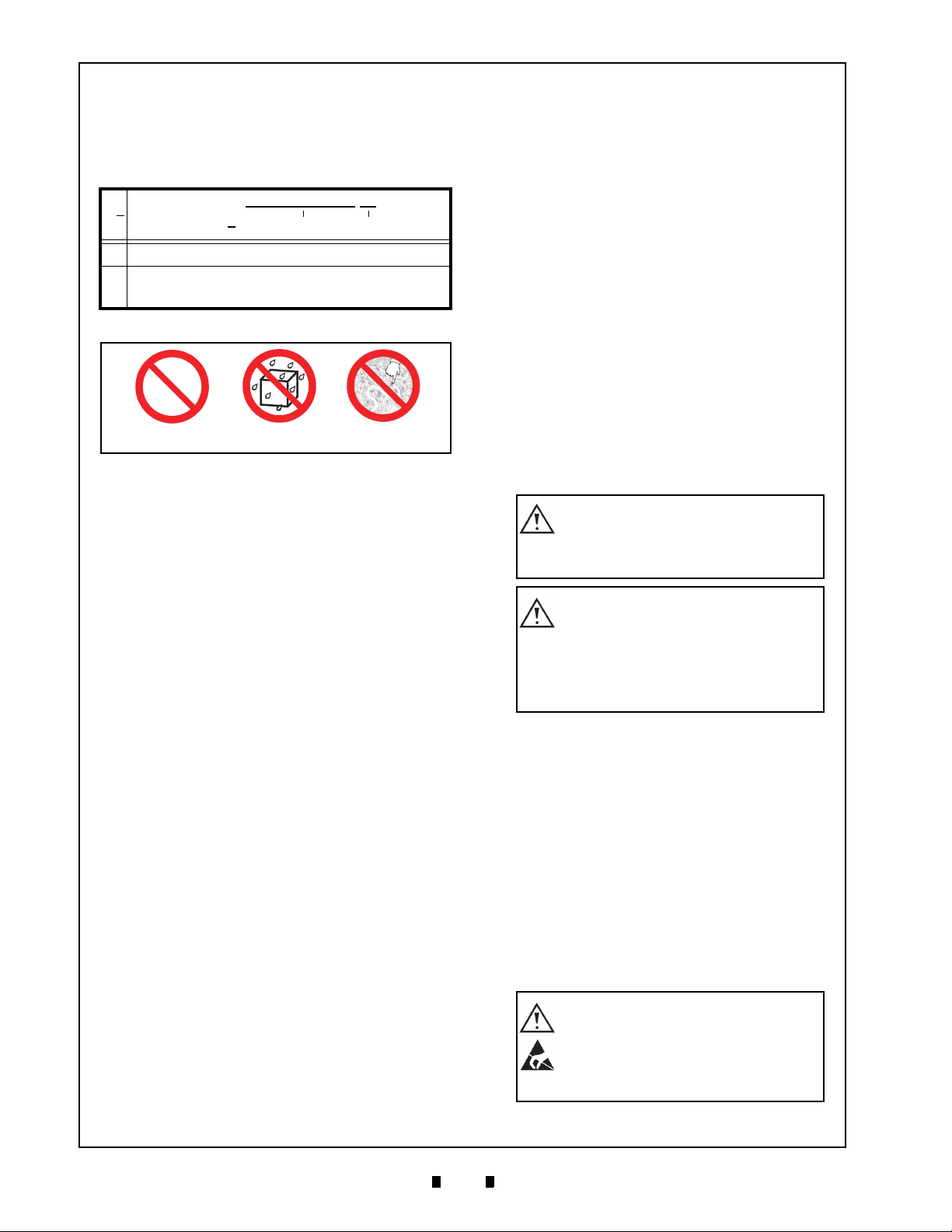
Precautions
Symbols in Figure 2 are defined as follows:
1. (Type 1) Do not insert a torn, folded, or wet
Banknote; it may cause a jam inside the unit.
2. (Type 2) Do not expose the unit to water. The unit
contains several precision electronic devices that
can be damaged if water or any liquid is sprayed
or spilled into the unit.
3. (Type 3) Do not install the unit in a dusty
environment. Dust may affect/degrade the sen-
sor’s performance.
U
SER
C
AUTIONS
Careful measures were taken in the design of this
product to ensure its quality; however, the follow-
ing cautions pertain to all users and should be fol-
lowed for safe operation.
Installation Cautions
The Installation Cautions are defined as follows:
1. Do not allow the unit to endure or operate at a
high temperature, in high humidity and/or dusty
environment.
2. Do not install the unit in an area with excessive
vibration or shock present.
3. This equipment is not fully warranted for outdoor
use. Be sure that the host machine contains
enough protection to avoid wet or dusty condi-
tions when installing it in either an indoor or
open-air space.
4. Avoid exposing the unit to direct sunlight/incan-
descent lamp illumination with a gradient angle
of 15 degrees or more, and an illumination index
of 3,000 Lux or less.
5. Ensure that the host machine is designed for daily
operational access for maintenance and/or clear-
ing a Banknote Jam.
Mounting, Dismounting & Transportation
Methods for mounting, dismounting and transport-
ing the unit:
1. Be sure to turn the VEGA Unit’s power OFF
before mounting or removing the Recycler unit.
2. Plugging or unplugging the Recycler’s communi-
cations connector while the VEGA Unit’s power
is ON may cause damage to the Recycler unit.
3. When reassembling a disassembled section,
ensure that each part is carefully placed in its
proper location.
4. Be sure to carry the unit using both hands. Hold-
ing the unit with only one hand may cause per-
sonal injury (if the unit comes apart).
5. While transporting, be careful not to apply too
much pressure to the unit, or subject it to excess
vibration.
6. Do not throw or pound on the unit.
Preventive Maintenance
The preventive maintenance requirements are
defined as follows:
1. When closing the Rear Cover of the Recycler,
ensure that it clicks firmly into place.
2. Use a soft, lint-free cloth, cotton swab or com-
pressed air spray to clean dust and debris from the
Rollers.
3. Perform routine cleaning and maintenance at least
once a month to keep the VEGA Recycler Unit’s
performance stable.
4. Be sure that the Guides and unit sections are
placed in the proper location after a maintenance
procedure.
5. Do not replace Banknotes by hand-winding them
back into place; instead, use the unit’s recycling
action ONLY.
6. Do not redesign or disassemble the Recycler.
Unauthorized use by inadequately trained person-
nel, or use outside the original manufacturer’s
intent, voids the warranty.
Table 1 VEGA-RC Twin Model Number
Specifications
NoModel: VEGA-RC Twin * *
No(1) (2)
(1) Product Series Name
(2) Input Power Source
12 = 12V DC Power Source
42 = 24 - 36V DC Power Source [MDB Specification] (option)
Type 1 Type 2 Type 3
Figure 2 Precautionary Symbols
Caution: Be careful to avoid any
personal injury to fingers when
closing the Rear Cover of the
Recycler.
Caution: Turn the VEGA Unit’s
power supply OFF when opening
the Rear Cover; otherwise, the
rollers could begin operating and
cause injury by pulling fingers into
the unit.
WARNING: DO NOT use a cleaning
cloth wet enough to allow excess
fluid to run into the device;
internal printed circuit boards may
be damaged.