Ripley MILLER VIS500 User manual

Page 1
VIS500 User Guide
VIS500
Wireless Fiber Inspection Scope
User Guide

Page 2
VIS500 User Guide
Contents
Introduction 3
Device Overview 3
Endface Cleaning and Inspection Procedure 5
Connecting on IOS 7
Connecting on Android 8
Connecting on Windows PCs/Tablets 9
Integration with Desktop InSpec 10
Integration with Mobile InSpec 14
Certications and Contact Information 18

Page 3
VIS500 User Guide
The VIS500 Fiber Inspection Scope is a low cost, Auto Focus Wireless Inspection scope for verrifying compliance with the
IEC 61300-3-35 Specication. This document will serve as an overview of the major features and functions of the device
as well as instructions for use with the Windows, and mobile InSpec applications. If you are looking for a standalone
inspection system take a look at the VIS300C inspection system. Or if you are looking for a device that can be used with
windows at a lower cost take a look that the VIS500
Introduction
MFB Button
When pressed this will initiate a focus and analyze
routine by default however it can be changed in the
software
Charging Port
The USB cable is used to connect to the
VIS300C or windows PC
Connector Adapter
The VIS500 comes with a universal 2.5 adapter by
default, however additional adapters are available and
are user replaceable.
Device Overview
Status Light
This light is used to display the connection status
of the VIS500 aswell as Display Pass Fail Results
Charging Status LED
This LED is used to show the battery and
charging status.
Power Button
This button when held for 5 seconds
power on or o the device.

Page 4
VIS500 User Guide
Charging Status LED
Status Light
Changing the Inspection Tip
The Charging LED will display battery information when unplugged, or charging status when plugged in. When
unplugged a solid green light will be displayed when the device is above 30 percent battery. Below it will display a red
light and when critical begin blinking. When plugged in it will blink green when charging and stay solid green once fully
charged.
The status light is used to describe the connection status and the results of an analysis. When the unit rst turns on
it will slowly blink blue to indicate that it is waiting for a connection. To connect to the device see the connection
instructions for your given platform. Once connected and in the application the light will turn solid blue indicating that it
is connected. From this point on Solid blue will be the standby color and will be displayed when the unit is ready to focus
and analyze. After any focus and analyze the LED will turn either Red to indicate a failed focus/ Failed ber or green to
indicate a passing ber.
To change the adapter tip simply hold the adapter still and rotate the adapter ring, replace the adapter then tighten the
ring back down.

Page 5
VIS500 User Guide
Endface Cleaning and Inspection Procedure
Intro
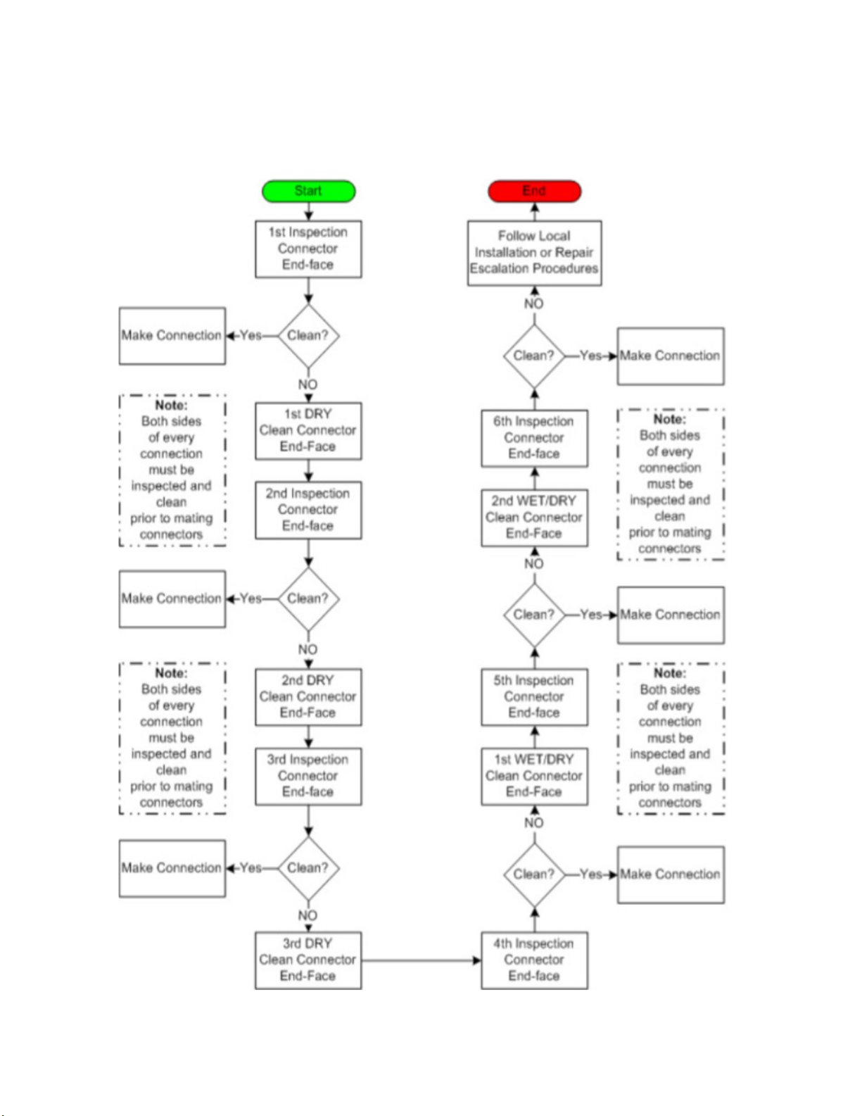
Nearly 95% of all ber optic system failures can be attributed to dirt on the ber endface. Such situations are often
entirely avoidable if proper cleaning procedures are followed. The International Electro technical Commission (IEC) has
created a standard of ber endface cleanliness, as well as a thorough ber cleaning procedure used to achieve that
standard. Industry best practices dictate strict adherence to this procedure in order to achieve optimal optical links
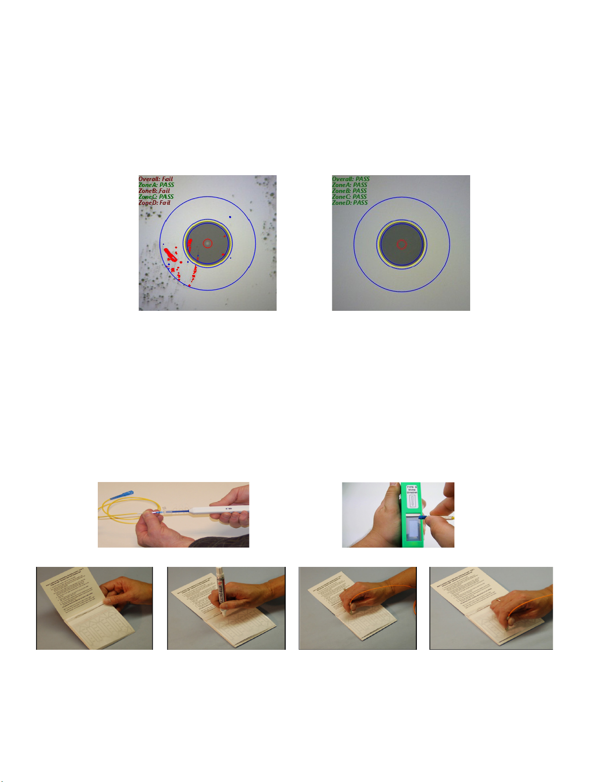
Fibers like the one shown in the “Before Cleaning” image (above) are c ommonly seen before installation. When bers
are improperly protected dust and debris can make their way onto the endface. The problem of dirt on ber enfaces can
be compounded by the presence of adhesive residue due to poor ber storage techniques. The IEC has laid out a dry
and wet/dry cleaning process that accounts for both the supercial and more stuborn debris that may be found on ber
endfaces.
Dry Cleaning
Dry cleaning connector endfaces is accomplished using a one-click or cletop cleaner. the one-click cleaner is used by
simply inserting a ber into the adapter cap and pushing until the unit clicks. The cletop cleaner can be used by retracting
the door on the body of the device to reveal a lint-free dry pad, and then rmly pressing the ber endface into the pad
and dragging downward. Both methods will most likely remove dust and other moveable debris.
Wet/Dry Cleaning
The wet/dry method (shown above) utilizes a lint-free pad and a ber wash pen lled with a solution of alchohol. To use
this method:
1. isolate a pad so it is on top of the laminated arrow sheet
2. place a coin sized spot of solution on the wipe using the pen
3. rub the ber endface into the wet portion of the pad.
4. drag the ber downward to the dry part of the pad, applying steady pressure. This method is helpful for removing
stubborn debris
Before Cleaning After Cleaning
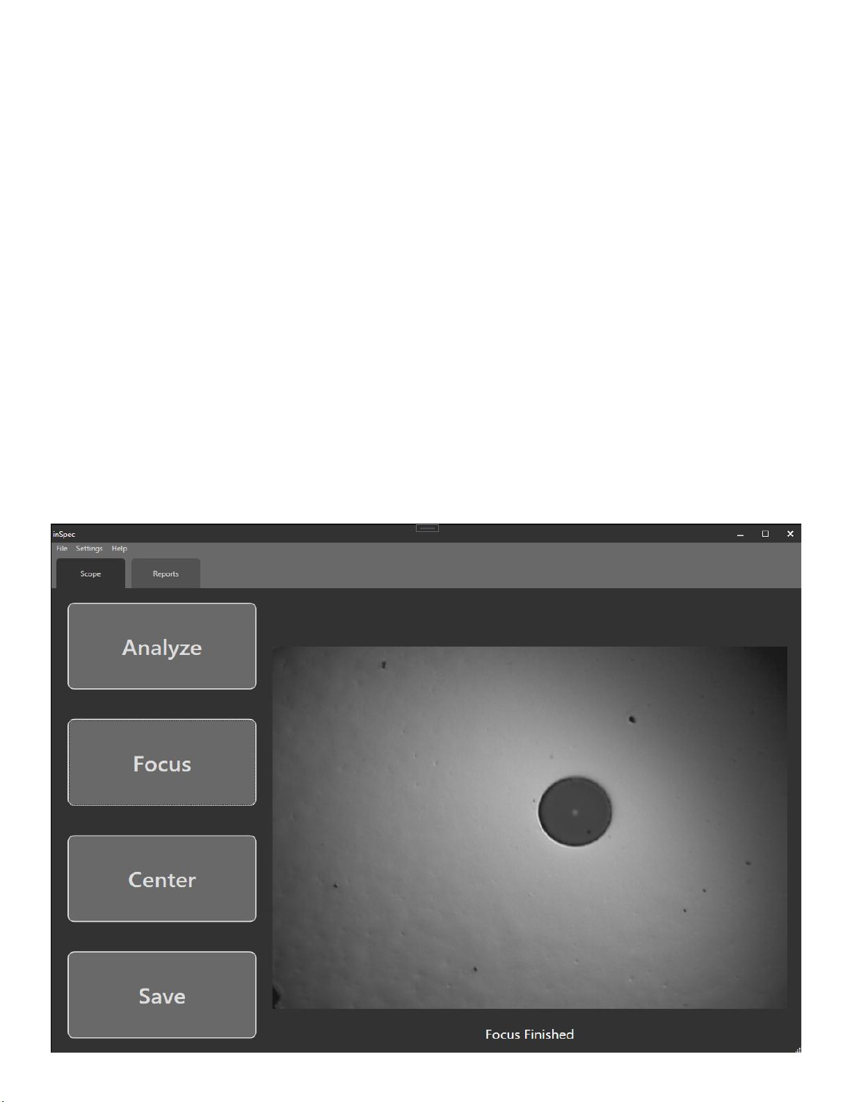
Auto Analyzed images from the VIS500 and the windows inspec
software

Page 6
VIS500 User Guide
The appropriate, IEC-specied cleaning and inspecting procedure tasks the technician with examining the ber endface
with an inspection scope and performing the necessary cleaning actions. If a connector endface is particularly dirty, three
dry cleanings must be performed, followed by two wet/dry cleanings. Connectors still contaminated with unmovable
debris after the full procedure has been attempted may need to be replaced.

Page 7
VIS500 User Guide
Connecting to the VIS500 on IOS
To connect the VIS500 on IOS rst go to the settings app and press “Wi” as shown in the screenshots below.
Next wait until a SSID Showing “VIS500” followed by the 4 digit start to your serial number. Once that appears click it and
wait for the check mark to appear next to the ssid. Finally open or return to the Mobile InSpec application.

Page 8
VIS500 User Guide
Connecting to the VIS500 on Android
To connect the VIS500 on Android rst go to the settings app and press “Network and internet” then “Wi as shown in the
screenshots below.
Next wait until a SSID Showing “VIS500” followed by the 4 digit start to your serial number. Once that appears click it it to
nish connecting. Finally open or return to the Mobile InSpec application.

Page 9
VIS500 User Guide
Connecting to the VIS500 on Windows
To connect the VIS500 on Windows rst go to the bottom right of yoru screen and press the Wi or networking button.
or .
Next wait until a ssid with VIS500 and the rst four digits of your serial number is shown. then click it and wait for windows
to nish connecting to the device. Afterwords return or launch the Windows InSpec Application

Page 10
VIS500 User Guide
Integration with Desktop InSpec
InSpec is a free software package from Ripley oering complete inspection, saving, and reporting of
pertinent ber endface images for ber optic installations. This software is available for download at
Ripley-tools.com/download.
Connection
To connect the VIS500 to the windows inspec software rst connect the wi as shown for your specic
platform above. once you are connected to the device on wi open the Desktop software. if the
software is already open press “Settings”=>”Check for wi scope” to check for the device.
Analyzing and saving a ber with the InSpec Software
Once you connect the VIS500 the “Scope” tab will appear and you will see the screen below with a live
image of the ber endface. At this point you should use the focusing ring to focus the endface image.
Next make sure you have the correct IEC-Spec is selected. To change your selected IEC-Spec press
“Settings”=>IEC-61300-05-35=> then your given ber type (such as UPC, APC, MMPC etc). Finally
once the image is focused and the correct spec is chosen press the “Analyze” button to automaticaly
center the image, detect any defects visible and assign a pass fail value to each zone on the ber, and
color passing defects blue, and failing defects red.
Focusing a ber
To focus a ber simply press the “Focus” button then wait for the software to say “Focus Finished”

Page 11
VIS500 User Guide
Once you have an image you want to save, weather it is analyzed or just a live image pressing the
“Save” button will open the popup below. First you need to enter a name for the ber, next you need
to assign a location for the ber. if you want to save to the next available index just leave “Auto Assign
Location” checked as shown in the picture below. Finally add a comment if you choose and press save
to save the ber.

Page 12
VIS500 User Guide
Next before generating reports you may want to enter information such as the customer/contact
name, site ID/location or your Scope/Power meter serial numbers for tracking. To show this
information on your generated reports click Settings>Report Settings.
All information in the dark and light boxes are editable. The default settings are shown above. Click
“Reset to Defaults” to return to this arrangement of information. Enter all info as needed and click
Save to have the information appear on reports.
The Ripley Miller logo will appear on reports. Click Browse to choose a dierent logo to place on the
report, if desired.
Changeing the selected “Report Type” will change what format the reports are generated as. Currently
PDF, HTML, XML, and Excel are supported
Setting Report Settings

Page 13
VIS500 User Guide
Once you have entered all of your report information, have inspected all of your bers, and are happy
with your entered names. To generate your closeout report ensure you are on the “Reports” tab and in
the top left press “Generate”=>”Inspection Report”.
Generating a Closeout Report
First ensure you are on the “Reports” tab. here on the left side you will see any Endface images you
have saved along with their comments. on the right you will see any OPM readings you took on a
Ripley power meter. if you want to rename any reading or inspection press them then press “Edit” or
double click them to open the edit popup. once you have edited the name / comment simply press
save again.

Page 14
VIS500 User Guide
Integration with Mobile InSpec
To begin streaming from the device press the “Inspection Page” button and wait while it detects,
connects, and begins streaming from the VIS500. if you run into issues getting the device to stream or
be detected verify that you have allowed location access, and local network access. both permissions
are required to use a local network device (such as the VIS500).
Connection
To connect the VIS500 to the windows inspec software rst connect the wi as shown for your
specic platform above. once you are connected to the device on wi open the mobile app and it will
automatically connect to the VIS500. you will know its connected when the Blue light stops blinking.
Streaming from the device

Page 15
VIS500 User Guide
Analyzing and saving a ber with the InSpec Software
Once connected to the VIS500 and streaming you can see your selected IEC-Spec in the top right.
To select a new one click the Settings cog in the top right then change “IEC_Spec” to your preered
spec. Next to Focus you can either use the manual focus bottons on the left or the Focus button on
the right. Finally pressing analyze will analyze the current image and display the results. This can all
be done in one click by pressing the MFB button on the unit, or by pressing the Focus and Analyze
button in the software. Once you have a ber you wish to save pressing QuickSave will immediately
save it with either an index name or a color code name if selected. Pressing Save however will let you
name the ber and add a comment before saving.

Page 16
VIS500 User Guide
Next before generating reports you may want to enter information such as the customer/contact
name, site ID/location or your Scope/Power meter serial numbers for tracking. To edit this information
return to the home page by pressing back from the inspection page. Next go to the “Reports” page
then press the settings cog in the top right.
All information in the boxes are editable. The default settings are shown above. Click “Reset to
Defaults” to return to this arrangement of information. Enter all info as needed and click Save to have
the information appear on reports.
Changeing the selected “Report Type” will change what format the reports are generated as. Currently
PDF, HTML, XML, and Excel are supported on all platforms
Setting Report Settings

Page 17
VIS500 User Guide
Finally to nish generateing reports simply press “Make Report”, verify your report format and select
your report type. Inspection will generate a report with all of your endface inspections, OPM will
generate one with all power meter readings, Fiber will combine each indexes inspection ( near and far)
with that indexes readings. and Bi-Directional will combine near and far readings into one row for bi
directional OLTS testing.
Generating a Closeout Report
Once you have set your report settings returning to the reports page allows you to generate your
reports! rst quickly review your saved images and readings to verify you have all pertinent data and
it is all labeled correctly. to rename readings simply select either the reading or inspection and press
“Edit Selected”.

Page 18
VIS500 User Guide
Inspection Scope Accessories
Inspection Tip Adapters
Part Number Description
AC 034B E2000 Adapter AC040B SC Adapter
AC041B SC APC Adapter AC109B SC 60-degree adapter
AC042B FC Adapter AC104B FC 60-degree Adapter
AC043B FC APC Adapter AC044B LC Adapter
AC045B LC APC Adapter AC107B LC 60 Adapter
AC046B ST Adapter AC047B MTP APC Adapter
AC050B MTP Adapter AC048B 1.25 MM universal adapter
AC049B 2.5 mm Universal Adapter AC100B ODC Pin Adapter
AC101B ODC Socket Adapter AC105 ODC Adapter Plate
AC102 38999 Plug AC103 38999 Socket
Certications,Accessories, and Contact Info
The VIS500 comes with a 2 year warranty for any manufacturer defects or damage due to reasonable use. To start the
RMA process simply email or call technical support!
Warranty

Page 19
VIS500 User Guide
Contact us with any questions pertaining to this or any other Ripley product.
Call Us:
(603) 524-8350
Email Us:
tec[email protected]y-tools.com
Visit Us Online: www.ripley-tools.com
Contact Support
This device complies with Part 15 of the FCC Rules. Operation is
subject to the following two conditions: (1) this device may not cause
harmful interference, and (2) this device must accept any interference
received, including interference that may cause undesired operation.
This equipment has been tested and found to comply with the limits
for a Class B digital device, pursuant to part 15 of the FCC Rules.
These limits are designed to provide reasonable protection against
harmful interference in a residential installation. This equipment
generates, uses and can radiate radio frequency energy, and if not
installed and used in accordance with the instructions, may cause
harmful interference to radio communications. However, there is no
guarantee that interference will not occur in a particular installation. If
this equipment does cause harmful interference to radio or television
reception, which can be determined by turning the equipment o
and on, the user is encouraged to try to correct the interference by
one or more of the following measures:
• Reorient or relocate the receiving antenna.
• Increase the separation between the equipment and receiver.
• Connect the equipment into an outlet on a circuit dierent from
that to which the receiver is connected.
• Consult the dealer or an experienced radio/TV technician for help.
Certications and Contact Information
This product conforms with health, safety, and
environmental protection standards for products sold within
the European Economic Area (EEA). This product was tested
by an ISO 17025 accredited laboratory and complies with
the following CE directives and standards listed below:
Directives:
Electromagnetic Compatibility (2014/30/EU)
Low-Voltage (2014/35/EU)
Standards:
EMC: EN 61326-1:2013 Industrial
Safety: EN/IEC61010-1:2010+A1:2016
Table of contents
Other Ripley Test Equipment manuals
Popular Test Equipment manuals by other brands

AutoMeter
AutoMeter POSI-160 Operator's manual

Kyoritsu Electrical Instruments Works, Ltd.
Kyoritsu Electrical Instruments Works, Ltd. KEW3121B instruction manual

Socket & See
Socket & See SP 200 quick start guide

EL-CELL
EL-CELL PAT-Cell user manual

Pro-tec
Pro-tec class PROpolN LED 2.0 operating instructions

Shineway Tech
Shineway Tech WFT-20 user manual