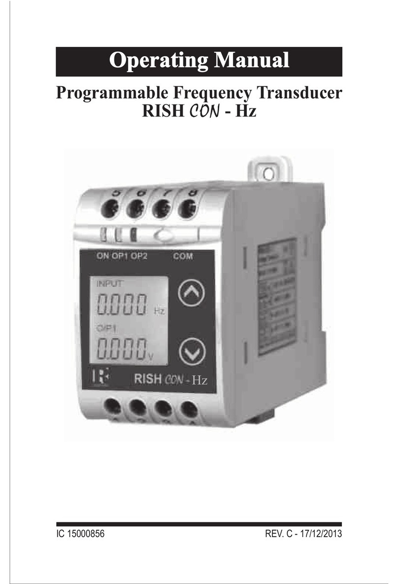
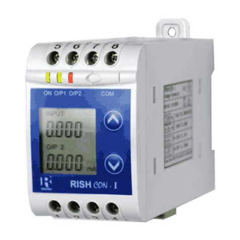
Rishabh RISH CON - V User manual

IC 15000930 REV. C - 17/12/2013
Programmable Voltage Transducer
RISH CON - V


1
Section Contents
1. Introduction
2. Input and Output screens
3. Programming
3.1 Programming via Front LCD & Two keys
3.1.1 Password Protection
3.1.1.1 Password Verification
3.1.1.2 Editing Existing Password
3.1.2 Potential Transformer parameter
Setting
3.1.2.1 Potential Transformer primary
value
3.1.2.2 Potential Transformer secondary
value
3.1.3 Communication Parameter Setting
3.1.3.1 Address Setting
3.1.3.2 RS 485 Baud rate
3.1.3.3 RS 485 Parity selection
3.1.4 Output Type Selection
3.1.4.1 Output 1 Type selection
3.1.4.2 Output 2 Type selection
3.1.5 Input Characteristics Setting
3.1.5.1 End value of input
3.1.5.2 Start value of input
3.1.5.3 Elbow Function Selection
3.1.5.4 Elbow value of input
Voltage Transducer
Programmable Voltage Transducer
Installation & Operating Instructions

3.1.6.1 Output 1 Characteristics Setting
3.1.6.1.1 End value of output 1
3.1.6.1.2 Start value of output 1
3.1.6.1.3 Elbow value of output 1
3.1.6.2 Output 2 Characteristics Setting
3.1.6.2.1 End value of output 2
3.1.6.2.2 Start value of output 2
3.1.6.2.3 Elbow value of output 2
3.2 Programming Via Programming port available at
front of Transducer using optional PRKAB601
Adapter.
Installation
5.1 EMC Installation Requirements
5.2 Case Dimension
5.3 Wiring
5.4 Auxiliary Supply
5.5 Fusing
5.6 Earth / Ground Connections
5.7 Maintenance
6. Specification
7. Connection Diagram
3.1.6 Output Characteristics Setting
3.3
DIP Switch Setting for Output
4.
Programming Via optional RS485(MODBUS)
communication port.
3.3.1
RS 485 ( ModBus )
5.
2

1. Introduction
The Voltage Transducer is a DIN Rail/wall mounted 43.5 X
65.5mm Transducer.
Input Voltage and Output Voltage/Current are displayed on
LCD and indicated by LED’s.
The Voltage Transducer is used to measure and convert AC
Voltage input into proportional DC current or voltage output
signal. Output signal generated is proportional to the True
RMS (upto 15th Harmonic) of the input Voltage.
Voltage Transducer can be
configured and programmed at
site for the following :
PT Primary ,PT Secondary, Input
Characteristics (i.e start, end and
elbow value of Input) and Output
parameters (i.e as Voltage or as
Current and start, end and elbow
value of outputs).
1.1 LED Indication
O/P 2
ON
O/P 1
LED
Red LED continuous ON
Green LED continuous ON
Green LED continuous ON
Green LED continuous ON
Red LED continuous ON
Output1 voltage
Output1 Current
Aux. Supply healthy condition
Output2 voltage
Output2 Current
LED OPERATING STATUS
LED OPERATING CONDITION
The front panel has two push buttons through which the user
may scroll through the output screens & configure the
product.
3

Screen 1 : Display Test Screen 2 : Version Screen
Screen 3 : Voltage Input & Screen 4 : Voltage Input &
Output 1 as Voltage Output 1 as Current
Table 1: Measured parameters
Measured parameters Unit of Measurement
Voltage V
2. Input and Output screens
In normal operation the user is presented with display test
screen followed by version screen to one of the output
screen. These screens may be scrolled through one at a
time by pressing the “ Up key” or “ Down key”.Ù Ú
4

3. Programming
3.1 Programming via Front LCD & Two keys
The following sections comprise step by step procedures for
configuring the Voltage Transducer for individual user
requirements.
To access the set-up screens press and hold the “ Down”
and “ Up” keys simultaneously for 5 seconds. This will
take the User into the Password Protection Entry Stage .
3.1.1. Password Protection
3.1.1.1 Password Verification
Password protection can be enabled to prevent
unauthorised access to set-up screens, by default password
protection is not enabled.
Programming of transducer can be done in three ways
3.1. Programming Via Front LCD & two keys.
3.2. Programming Via Programming port available at front of
Voltage transducer using optional PRKAB601 Adapter.
3.3. Programming Via optional RS485(MODBUS)
communication port.
Ú
Ù
5
Screen 5 : Voltage Input
& as Voltage
Screen 6 : Voltage Input &
Output 2 Output 2 as Current

by selecting a four digit number
other than 0000,setting a
password of 0000 disables the
password protection
Enter Password, prompt for first
digit. (*Denotes that digit will be
flashing).
Pressing the “ Down” key will scroll the value of the first
digit from 0 through to 9, the value will wrap from 9 round to 0.
Pressing the “ Up” key will advance the operation to the
next digit and set the first digit.
In the special case where the Password is “0000” pressing
the “ Up” key when prompted for the first digit will advance
to the “Password Set/Confirmed” screen.
Enter Password, first digit
entered, prompt for second digit.
(*Denotes that digit will be
flashing).
Pressing the “ Down” key will
scroll the value of the second
digit from 0 through to 9, the
value will wrap from 9 round to 0.
Pressing the “ Up” key will
advance the operation to the next
digit and set the second digit.
Enter Password, second digit
entered, prompt for third digit.
(*Denotes that digit will be
flashing).
Pressing the “ Down” key will
Password protection is enabled
Ú
Ù
Ù
Ú
Ù
Ú
6

scroll the value of the third digit from 0 through to 9, the
value will wrap from 9 round to 0.
Pressing the “ Up” key will advance the operation to
the next digit and set the third digit.
Enter Password, third digit
entered, prompt for (*Denotes
that digit will be flashing). fourth
digit.
Pressing the “ Down” key will
scroll the value of the fourth digit
from 0 through to 9, the value will
wrap from 9 round to 0.
Pressing the “ Up” key will advance the operation to the
“Password Set / Confirmed” and set the fourth digit.
Password Set / Confirmed.
Pressing “ Down” key will
enter to the “New change
Password” entry stage. (section
3.1.1.2)
Pressing the “ Up” key will
advance to the Potential
Transformer parameter
selection (section 3.1.2).
Password Incorrect.
This screen is displayed when
the unit has not accepted the
Password entered.
Pressing the " Down" key will
re -enter to the “Enter Password”
entry stage.
Pressing the “ Up” key will exit the setup menu.
Ù
Ú
Ù
Ú
Ù
Ú
Ù
7

3.1.1.2 Editing Existing Password
(*Denotes that digit will be
flashing).
Pressing the “ Down” key will
scroll the value of first digit from 0
through to 9, the value will wrap
from 9 round to 0.
Pressing the “ Up” key will
advance the operation to the next
digit and set the first digit, in this case to “4”
Enter New Password, first digit
entered, prompting for second
digit. (*Denotes that digit will be
flashing).
Pressing the “ Down” key will
scroll the value of the second
digit from 0 through to 9, the
value will wrap from 9 round to 0.
Pressing the “ Up” key will advance the operation to the
next digit and set the second digit, in this case to “1”
Enter New Password, second
digit entered, prompting for third
digit. (*Denotes that digit will be
flashing).
Pressing the “ Down” key will
scroll the value of the third digit
from 0 through to 9, the value will
wrap from 9 round to 0.
Pressing the “ Up” key will advance the operation to the
next digit and set the third digit, in this case to “4”
Ú
Ù
Ú
Ù
Ú
Ù
8

Enter New/ Change Password,
third digit entered, prompting for
fourth digit. (* denotes that digit
will be flashing).
Pressing the “ Down” key will
scroll the value of the fourth digit
from 0 through to 9, the value will
wrap from 9 round to 0.
Pressing the “ Up” key will advance the operation to the
“New Password Confirmed” and set the fourth digit, in this
case to “1”.
New/changed Password confirmed.
Pressing the “ Down” key will
re-enter to the “New/Change
Password” entry stage.
Pressing the “ Up” key will
confirm New Password &
advance to the Potential
Transformer parameter setting
(section3.1.2).
3.1.2. Potential Transformer parameter Setting
3.1.2.1 Potential Transformer primary value
This screen allows the user to
set the PT Primary value from
57V to 400kV.
Pressing the “ Down” key will
enter the “New/ Change PT
Primary value edit” mode.
Pressing “ Up” key will confirm
the present value as PT Primary
Ú
Ù
Ú
Ù
Ú
Ù
9

and advance to the PT secondary setting (section 3.1.2.2).
New / Change PT Primary
value
(*Denotes that decimal point will
be flashing).
Pressing the “ Down” key will
scroll the decimal point to the
next position.
Pressing the “ Up” key will
confirm the decimal point position & advance the operation
to set the first digit.
(*Denotes that digit will be
flashing).
Pressing the “ Down” key will
scroll the value of the first digit
from 0 through to 9, the value will
wrap from 9 round to 0.
Pressing the “ Up” key will
advance the operation to the next
digit and set the first digit, in this
case to “1”.
Enter New / Change PT Primary
value, first digit entered,
prompting for second digit .
(*Denotes that digit will be
flashing).
Pressing the “ Down” key will
scroll the value of the second
digit from 0 through to 9, the value will wrap from 9 round to 0.
Pressing the “ Up” key will advance the operation to the
next digit and set the second digit, in this case to “0”.
Ú
Ù
Ú
Ù
Ú
Ù
10

Enter New / Change PT Primary
value, second digit entered,
prompting for third digit.
(*Denotes that digit will be
flashing).
Pressing the “ Down” key will
scroll the value of the third digit
from 0 through to 9, the value will
wrap from 9 round to 0.
Pressing the “ Up” key will advance the operation to the
next digit and set the third digit, in this case to “0”.
Enter New / Change PT Primary
value, third digit entered,
prompting for fourth digit.
(*Denotes that digit will be
flashing).
Pressing the “ Down” key will
scroll the value of the fourth digit
from 0 through to 9, the value will
wrap from 9 round to 0.
Pressing the “ Up” key will advance the operation to the
“New / Changed PT Primary value” & set the fourth digit, in
this case to “0”.
New/changed PT Primary
value confirmed.
Pressing the “ Down” key will
re-enter to the “New / Change PT
Primary value”edit mode.
Pressing the “ Up” key will
confirm New PT Primary value
a n d a d v a n c e t o t h e P T
secondary setting (section 3.1.2.2).
Ú
Ù
Ú
Ù
Ú
Ù
11

3.1.2.2 Potential Transformer secondary value.
Pressing the “ Down” key will
enter the “New/Change PT
Secondary value edit” mode.
Pressing the “ Up” key will
confirm the present value as PT
Secondary and advance to the
Communication parameter
Setting (section 3.1.3).
New / Change PT Secondary value
(*Denotes that digit will be
flashing).
Pressing the “ Down” key will
scroll the value of the Second
digit from 0 through to 5, the
value will wrap from 5 round to 0.
Pressing the “ Up” key will
advance the operation to the next
digit and set the second digit, in this case to “5”
Enter New/Change PT
Secondary value, second digit
entered, prompting for third digit.
(*Denotes that digit will be flashing).
Pressing the “ Down” key will
scroll the value of the third digit
from 0 through to 9, the value will
wrap from 9 round to 0.
Pressing the “ Up” key will advance the operation to the
next digit and set the third digit, in this case to “0”.
Ú
Ù
Ú
Ù
Ú
Ù
12

E n t e r N e w / C h a n g e P T
Secondary value, third digit
entered, prompting for fourth
digit.
(*Denotes that digit will be
flashing).
Pressing the “ Down” key will
scroll the value of the fourth digit
from 0 through to 9, the value will wrap from 9 round to 0.
Pressing the “ Up” key will advance the operation to the
next digit & set the fourth digit, in this case to “0”.
New/changed PT Secondary value confirmed.
Pressing the “ Down” key will
re-enter to the “New / Change PT
Secondary value”edit mode.
Pressing the “ Up” key will
confirm New PT Secondary
value and advance to the
Communication parameter
Setting (section 3.1.3).
3.1.3. Communication Parameter Setting
3.1.3.1 Address Setting
This screen applies to the RS
485 output only.
This screen allows the user to
set RS485 parameter for
instruments
The range of allowable address
is 1 to 247 .
Pressing “ Down” key will
Ú
Ù
Ú
Ù
Ú
13

advance to the “New/Change address value edit” mode.
Pressing the “ Up” key will confirm the present value as
Address & advance to Baud Rate selection (section3.1.3.2).
New/changed Address value
(*Denotes that digit will be
flashing).
First digit is always blank.
Pressing the “ Down” key will
scroll the value of the second
digit from 0 to 2, the value will
wrap from 2 round to 0.
Pressing the “ Up” key will
advance the operation to the next digit and set the second
digit, in this case to “0”.
Enter New / Change Address
value, second digit entered,
prompting for third digit.
(*Denotes that digit will be
flashing).
Pressing the “ Down” key will
scroll the value of the third digit
from 0 through to 9, the value will
wrap from 9 round to 0.
Pressing the “ Up” key will
advance the operation to the next
digit and set the third digit, in this
case to “9”.
Enter New / Change Address
value, third digit entered,
prompting for fourth digit.
Ù
Ú
Ù
Ú
Ù
14

(* denotes that digit will be flashing).
Pressing the “ Down” key will scroll the value of the fourth
digit from 0 through to 9, the value will wrap from 9 round to 0.
Pressing the “ Up” key will advance the operation to the
“New / Changed Address value confirmed” and set the fourth
digit, in this case to “6”.
New/changed Address value confirmed.
Pressing the “ Down” key will
re-enter to the “New / Change
Address value edit” mode.
Pressing the “ Up” key will
confirm New Address value and
advance to Baud Rate selection
(section3.1.3.2) .
3.1.3.2 RS 485 Baud rate
This screen allows the user to set
Baud Rate of RS 485 port.
The values displayed on screen
are in kbaud ..
Pressing the “ Down” key will
enter the “Baud Rate edit” mode
and scroll the value through 2.4,
4.8, 9.6 , 19.2 and back to
2.4(values are flashing).
Pressing “ Up” key will confirm the present value as
Baud rate & advance to the Parity Selection (section3.1.3.3).
RS 485 Baud Rate confirmation
Pressing “ Down” key will be re-enter into the “Baud Rate
Ú
Ù
Ú
Ù
Ú
Ù
Ú
15

16
Edit” mode
Pressing the “ Up” key will
confirm the Baud ratevalue and
advance to the Parity Selection
(section 3.1.3.3).
3.1.3.3 RS 485 Parity selection
This screen allows the user to set Parity & number of stop
bits of RS 485 port.
Pressing the “ Down” key will
enter the “Parity & stop bit edit”
mode and scroll the value
through
odd : odd parity with one stop bit
no. 1S : no parity with one stop bit
no. 2S : no parity with two stop bit
E : even parity with one stop bit
Pressing “ Up” key accepts the present value and advance
to the Output Type selection (section 3.1.4).
RS 485 Parity confirmation
Pressing “ Down” key will be
re- enter into Parity Edit mode.
Pressing the “ Up” key will set
the value and advance to the
Output Type selection (section
3.1.4).
Ù
Ú
Ù
Ú
Ù

17
3.1.4. Output Type Selection
3.1.4.1 Output 1 Type selection
This screen allows the user to set
the output 1 type as Voltage or
Current.
Pressing the “ Down” key will
enter the “output 1type edit”
mode and scroll between
voltage and current.
Pressing “ Up” key will confirm
the present type for Output 1 and advance to the Output 2
type selection (section 3.1.4.2).
Output 1 Type confirmation
Pressing “ Down” key will re-
enter into Output 1 type Edit mode.
Pressing the “ Up” key will set
the type and advance to the
Output 2 type selection
(section 3.1.4.2).
3.1.4.2 Output 2 Type selection
This screen allows the user to set the output 2 type as
Voltage or Current for dual output
transducer.
Pressing the “ Down” key will
enter the “output 2 type edit”
mode and scroll between
voltage and current.
Pressing “ Up” key accepts
the present type for Output 2
Ú
Ù
Ú
Ù
Ú
Ù

18
& advance to the Input Parameter selection (section 3.1.5).
Output 2 Type confirmation
Pressing “ Down” key will re-
enter into Output 2 type Edit
mode.
Pressing the “ Up” key will set
the type & advance to the Input
Characteristics selection
(section 3.1.5).
3.1.5. Input Characteristics setting
3.1.5.1 End value of Input
This screen allows the user to set
the End value of Input.
End value of Input can be set 80%
to 120% of set PT secondary
value.
Pressing the “ Down” key will
enter the “New/Change End
value of Input edit” mode.
Pressing “ Up” key will confirm the present value as End
value of Input and advance to the Start value of Input
selection (section 3.1.5.2).
New / Change End value of Input
(*Denotes that digit will be flashing).
Pressing the “ Down” key will scroll the value of the
Ú
Ù
Note
After Changing Output Type please insure to change DIP
Switch setting (Refer Section 3.3.1). If DIP Switches are
already change then switch ON/OFF Transducer.
Ú
Ù
Ú
Table of contents
Other Rishabh Transducer manuals
Popular Transducer manuals by other brands
Airmar
Airmar TRIDUCER B744V Owner's guide & installation instructions
Balluff
Balluff PROFI BUS BTL5-T1 M Series Condensed guide
Humminbird
Humminbird APEX Series installation guide
Allen-Bradley
Allen-Bradley PowerFlex 4M installation instructions
WHD
WHD Exciter X.25-4 quick start guide
Licht
Licht MFC-300/IT Technical manual
