RITM OKB ZAO SCENAR Home User manual

RITM OKB ZAO
TRANSCUTANEOUS ELECTROSTIMULATORS
SCENAR Home,
SCENAR Sport,
SCENAR Basic
OPERATING MANUAL
MANUFACTURER
RITM OKB ZAO
99, Petrovskaya str., Taganrog, Russia, 347900
Tel/Fax: +7 (8634) 62-31-79
www.scenar.com.ru e-mail: medsc@scenar.com.ru
AUTHORIZED REPRESENTATIVE
SCENAR Center –Bulgaria ltd.
9, V. Aprilov blvd. Plovdiv, 4002, Bulgaria
Operating Manual Version 6.3-04 of 10.10.18
2
IMPORTANT INFORMATION!
PLEASE READ THIS PAGE CAREFULLY
WARNING! This device should NOT be used on an individual who has a heart pacemaker
or other electrically powered implant fitted.
WARNING! Application of electrodes near the thorax may increase the risk of cardiac
fibrillation.
WARNING! Simultaneous connection of a patient to h.f. surgical equipment may result in
burns at the site of the stimulator electrodes and possible damage to the stimulator.
WARNING! Operation in close proximity (e.g. 1 m) to shortwave or microwave therapy
equipment and mobile communicators may produce instability in the stimulator output.
WARNING! Aged people, children, and people with disabilities may not use the stimulator.
WARNING! The device needs special precautions regarding EMC and needs to be in-
stalled and put into service according to the EMC information provided in Annex 1.
WARNING! As the current densities for electrodes exceed 2 mA r.m.s./cm2, the device
requires the special attention of the user.
WARNING! The device should not be used adjacent to or stacked with other equipment.
This appliance is marked according to the European directive 2002/96/EC on Waste
Electrical and Electronic Equipment (WEEE). By ensuring this product is disposed of correct-
ly, you will help prevent potential negative consequences for the environment and human
health, which could otherwise be caused by inappropriate waste handling of this product.
The symbol on the documents accompanying the product indicates that this ap-
pliance may not be treated as household waste. Instead it shall be handed over to the appli-
cable collection point for the recycling of electrical and electronic equipment.
Disposal must be carried out in accordance with local environmental regulations for
waste disposal.
For more detailed information about treatment, recovery and recycling of this product,
please contact your local city office, your household waste disposal service or the shop
where you purchased the product.

Operating Manual Version 6.3-04 of 10.10.18
3
Origin: RITM OKB ZAO, 99, Petrovskaya str., Taganrog, Rostov region,
347900, Russia.
Model(s): SCENAR Home, SCENAR Sport, SCENAR Basic.
Classification: Type of protection against electric shock –Internally
powered equipment (9 V battery) Degree of protection against electric
shock –Type BF.
Waterproofing: No special protection against liquid ingress provided
(IPX0).
Cleaning & Disinfecting: Wipe electrode area with a cotton swab damp-
ened with 3 % hydrogen peroxide solution with the addition of 0.5 % solu-
tion of an approved cleaning liquid. Allow to dry up thoroughly before use.
Clinical environment: NOT suitable for use in the presence of flammable
anaesthetic mixtures with air, oxygen or nitrous oxides.
DO NOT REMOVE the upper casing –this access is for the use of
service personnel only.
Batteries: Remove battery from device if not in use for an extended
period. Connect correctly.
DO NOT TRY TO RECHARGE disposable batteries! Dispose of used
batteries responsibly. Use good quality, within-date long-life, 9 V
ALKALINE Type 6F22KG, 1604, 6LR61.
Note:
Remove battery during storage and transportation to avoid bat-
tery drain. Do not operate the device with the battery cover re-
moved, as this exposes the operator to live battery circuits in
contravention of the Safety Regulations.

Operating Manual Version 6.3-04 of 10.10.18
4
MARKS AND SYMBOLS ON THE DEVICE LABEL
THIS CE SYMBOL CERTIFIES THAT
THE PRODUCT COMPLIES WITH THE
ESSENTIAL REQUIREMENTS OF THE
MEDICAL DEVICE DIRECTIVE
Notified Body No.2265
3EC International a.s., Hraničná 18,
Bratislava, 82105, Slovakia
APPLIED PARTS –TYPE BF
MANUFACTURER combined with DATE
OF MANUFACTURE
SN-XXXX
SERIAL NUMBER
CONSULT INSTRUCTIONS FOR USE
AUTHORISED REPRESENTATIVE IN
THE EUROPEAN COMMUNITY

Operating Manual Version 6.3-04 of 10.10.18
5
DEFINITIONS
Amplitude modulation (Am) is a periodic variation of stimuli amplitude
(as well as stimuli Energy). Am is defined as the ratio of the time the
device is sending pulses with preset Energy to that with minimal En-
ergy. For example, the ‘3:1’Am setting indicates that the device is
transmitting stimuli with preset Energy for 3 seconds and then with
Energy = 1 for 1 second. Amplitude modulation manifests itself as
strengthening and weakening the specific sensations with a set period.
Dose is a signal to the operator that the rate of skin impedance change has
sufficiently reduced.
Dosed Stimulation determines the type of dosing provided by the device.
When the Dosed Stimulation is switched ON, the stimulation time for a
zone is determined automatically. When the Dosed Stimulation is
switched OFF, the zones to be treated, stimulation time for each zone and
time of the whole session are determined by the therapist.
Energy is a parameter determining strength of every stimulus. The Energy
influences stimulus amplitude and strength of stimulation sensation.
The higher the Energy, the stronger the specific sensations felt by the
patient.
Electrodes are сutaneous electrodes (built-in electrode and add-on electrodes)
that are applied directly to patient’s skin for electrical stimulation.
Frequency (F) is a number of stimuli (or stimuli bursts) per second,
measured in Hertz (Hz). When Frequency changes the strength and
'volume' of sensations also change.
Frequency modulation (Fm) is a periodical change of stimuli Frequency
from initial to final Frequency value and back. The sensations are
similar to those accompanying manual Frequency change.
Impedance is determined by the combined physical characteristics of the
skin, defining its ability to absorb the Energy generated by the device.
Stimulus is a single two-phase output pulse.

Operating Manual Version 6.3-04 of 10.10.18
6
CONTENTS
MARKS AND SYMBOLS ON THE DEVICE LABEL......................................4
DEFINITIONS........................................................................................................5
1 PURPOSE..........................................................................................................7
2 SPECIFICATIONS ............................................................................................8
3 PACKAGE CONTENTS.................................................................................11
4 SCENAR DEVICE OVERVIEW ....................................................................12
4.1 SCENAR HOME ........................................................................................12
4.2 SCENAR SPORT........................................................................................16
4.3 SCENAR BASIC ........................................................................................21
5 GETTING STARTED......................................................................................23
5.1 SCENAR HOME ........................................................................................23
5.2 SCENAR SPORT........................................................................................25
5.3 SCENAR BASIC ........................................................................................26
6 USING SCENAR DEVICE .............................................................................27
6.1 SCENAR HOME ........................................................................................27
6.2 SCENAR SPORT........................................................................................28
6.3 SCENAR BASIC ........................................................................................28
7 MAINTENANCE ..............................................................................................29
8 TROUBLESHOOTING ...................................................................................30
9 WARRANTY ....................................................................................................32
10 TRANSPORTATION AND STORAGE......................................................33
ANNEX 1..............................................................................................................34

Operating Manual Version 6.3-04 of 10.10.18
7
1 PURPOSE
SCENAR Home biofeedback transcutaneous electrostimulator
with individual dosing of reflex zone stimulation;
SCENAR Sport transcutaneous three-mode electrostimulator with
individual dosing of reflex zone stimulation;
SCENAR Basic transcutaneous dual-mode electrostimulator with
individual dosing of reflex zone stimulation.
SCENAR Home, SCENAR Sport, SCENAR Basic transcutaneous
electrostimulators (hereinafter called the SCENAR device or the device or
SCENAR) are intended for general therapeutic non-invasive treatment of
the human skin in order to remove pain of different etiology, alleviate dis-
eases, and speed up the recovery process of the organs and systems in the
course of combined therapy of different diseases.
The SCENAR device can be used:
by home users and in medical and prophylactic institutions to re-
move or reduce pain syndromes of various genesis, swelling, to
speed up the recovery process and prevent complications after
traumas of any kind and also to restore dysfunctions of the body in
various diseases;
only in medical and prophylactic institutions –as a stand-alone
treatment or alongside other therapies to remove postsurgical pain
syndrome and acute pain (including renal colic).
The SCENAR device is intended for use over a temperature range of
10 C to 35 C, and relative humidityup to 80 % at 25 C.
Potential risk from the device usage refers to Class IIa (2a)
DIRECTIVE 93/42/EEC (GOST R 31508).
The device complies with the standards EN 60601-1 (GOST R
50267.0) and EN 60601-2-10 (GOST R 50267.10) for internally powered
equipment, type BF, which classifies it as a safe device for personal use.
Operating Manual Version 6.3-04 of 10.10.18
8
2 SPECIFICATIONS
2.1Power supply: one 9 V alkaline battery.
2.2Current consumption: max –85 mA.
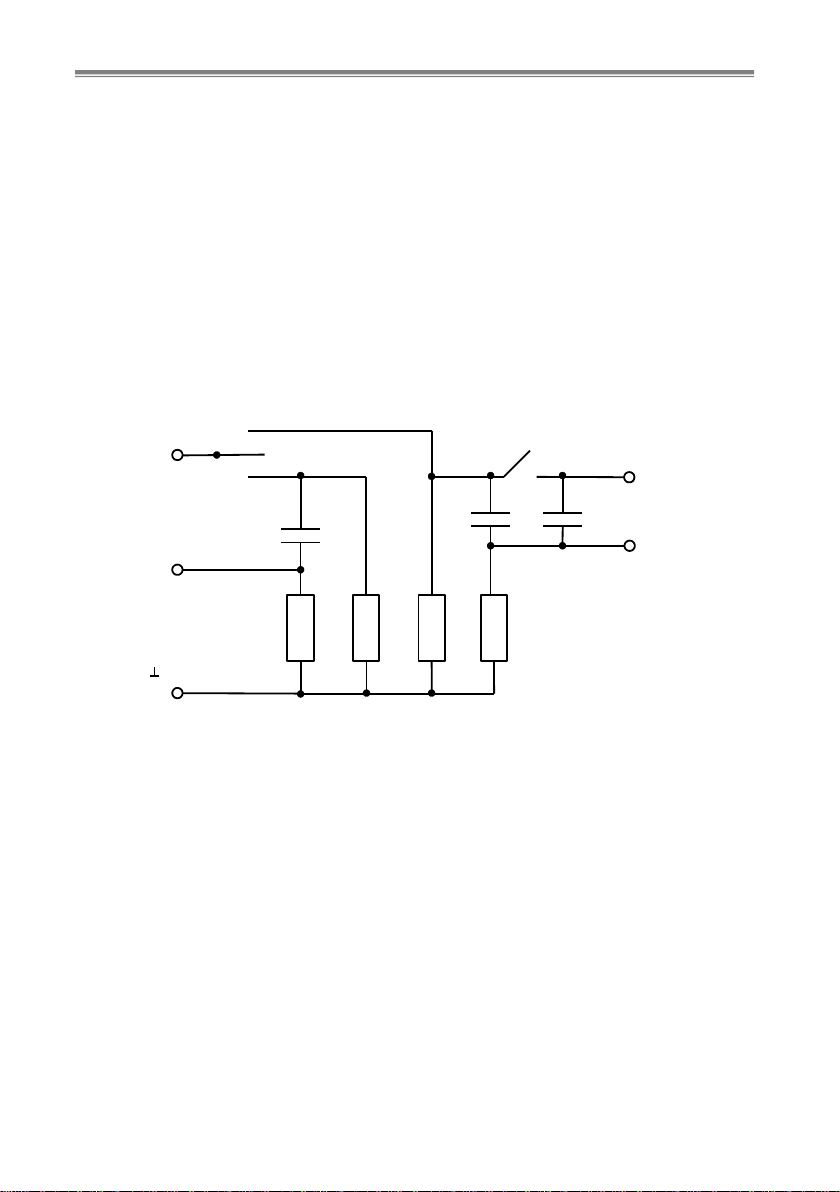
2.3At a load (see Fig.1) SCENAR performs:
generation of two-phase stimuli without a DC-component (see
Fig.2) with a waveform depending on the skin impedance under
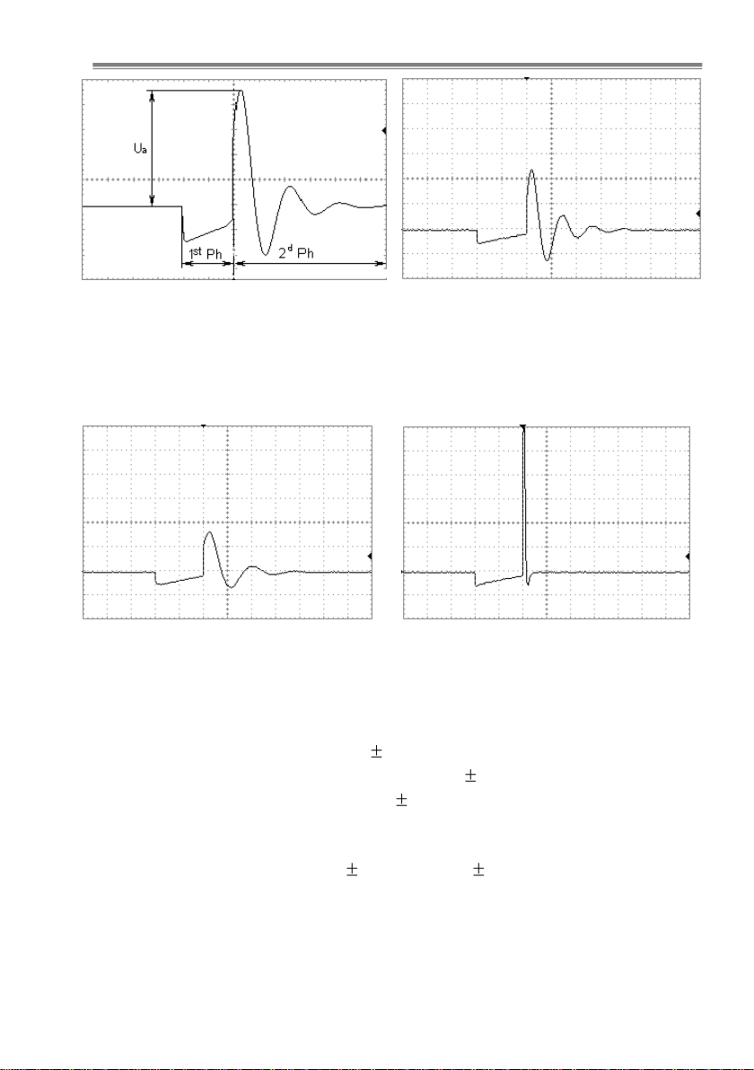
the electrode (see Fig.3 through 5);
control of the stimulus’ 1st phase duration (see Fig.2) within
(4 ±2) to (500 ±50) µsec, meanwhile the amplitude of the first
pulse of the stimulus’ 2nd phase at L1 load (see Fig.1) varies from
(1.7…2.8) V to (100…150) V. Amplitude control step –max 1 V.
C1
K73-11-630 V-2200 pF ±10 %
С2, С3
K73-11-250 V-0.033 μF ±10 %
R1
1/4W 11 kΩ±5 %
R2, R3
1/4W 91 kΩ±5 %
R4
1/4W 560 Ω ±5 %
M1…M3
are measuring points
Fig.1
“0”
“L1”
“L2”
C1 C2 C3
R1 R2 R3 R4
S1
T
M1
S2 M3
M2
Operating Manual Version 6.3-04 of 10.10.18
9
1st Ph –stimulus’ 1st phase duration
2dPh –stimulus’ 2nd phase duration
Ua–stimulus’ 2nd phase 1st pulse
amplitude Fig.2
Load L1; S2 –‘Off’,
load capacity –33 nF
Fig.3
Load L1, S2 –‘On’,
load capacity –66 nF
Fig.4
Load L2,
load capacity –2.2 nF
Fig.5
2.4Fixed stimuli frequencies:
SCENAR Home –90 Hz 10 %;
SCENAR Sport –14, 60, 90, 340 Hz 10 %;
SCENAR Basic –60, 90 Hz 10 %.
2.5Frequency modulation (‘Fm’) with the following parameters (only
for SCENAR Home and SCENAR Sport):
frequency range –(30 3) Hz to (120 12) Hz;
cycle of modulation –(7 ±2) sec.
Operating Manual Version 6.3-04 of 10.10.18
10
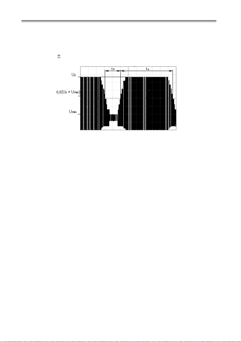
2.6Amplitude modulation (‘Am’, see Fig.6) with the following pa-
rameters:
duration of stimuli bursts with set amplitude –(3.0 ±0.5) sec;
pause (stimuli bursts with minimum amplitude value) duration –
(1.0 0.3) sec.
Umin –minimum amplitude
Us–set amplitude
tp–pause duration
tb–stimuli burst duration
Fig.6
2.7Time of dosed stimulation with L1 load:
SCENAR Home –20 to 40 sec;
SCENAR Sport –30 to 60 sec;
SCENAR Basic –45 to 75 sec.
2.8SCENAR device automatic turn-off time –(60 ±20) sec.
2.9SCENAR device weight: max –0.2 kg.
2.10Overall dimensions: max –140 x 55 x 35 mm.
2.11Average service life: min –5 years.

Operating Manual Version 6.3-04 of 10.10.18
11
3 PACKAGE CONTENTS
See Table 1 for SCENAR complete delivery set:
Table 1
Item
Quantity,
units
SCENAR Home –a biofeedback transcutaneous
electrostimulator with individual dosing of reflex zone
stimulation
SCENAR Sport –a transcutaneous triple-mode
electrostimulator with individual dosing of reflex zone
stimulation
SCENAR Basic –a transcutaneous dual-mode
electrostimulator with individual dosing of reflex zone
stimulation
9 V PP3 type battery (6F22KG, 1604)
1
Case
1
Consumer packaging
1
Operating Manual
1
Instruction for Use
1
Note:
1) On the customer’s request, SCENAR devices can be completed
with the following add-on electrodes:
–Face electrode
–Comb electrode
–Point electrode
–Special Snail electrode
–Bent point electrode
–Double facial Pawns electrode
–Double cosmetic electrode
–Double ophthalmic Goggles electrode
–Double facial Stamps electrode
–Single ophthalmic Monocle electrode
–Special double Pencils electrode
–Large comb electrode
–Multi-purpose zonal electrode
2) Add-on electrodes listed in item 1) can be purchased on the cus-
tomer’s request at extra cost.
Operating Manual Version 6.3-04 of 10.10.18
12
4 SCENAR DEVICE OVERVIEW
4.1 SCENAR HOME
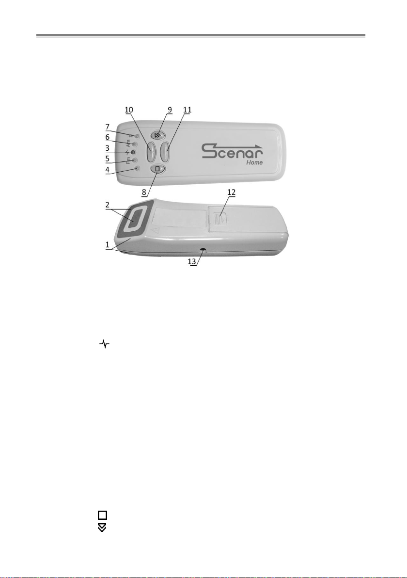
Fig.7 shows the SCENAR Home device exterior.
Fig.7
4.1.1 On the back side of the casing (1) there is a built-in electrode (2)
and a battery cover (12).
4.1.2 On the front side of the casing there are the following visual
indicators:
3–‘ ’ LED –indicates the energy level (stimulus strength);
4LED –the visual indicator of general purpose;
5 –‘Fm’LED –indicates the Frequency Modulation (‘Fm’)
mode preselecting;
6 –‘Am’LED –indicates the Amplitude Modulation (‘Am’)
mode preselecting;
7 –‘D’LED –indicates the Dosing mode preselecting.
The 4,‘Fm’, ‘Am’and ‘D’LEDs are as well used:
to indicate energy level (when adjusting the energy);
(optional) to display the levels of initial reactions and the dose
progress in the Dose 1 mode;
(optional) to display current reaction to the initial reaction ra-
tio in the Dose 2 mode.
4.1.3 On the front side of the casing there are following buttons:
8–‘’button –switches the SCENAR device ON and OFF;
9–‘’button –preselects the desired stimulation mode;

Operating Manual Version 6.3-04 of 10.10.18
13
10 –‘ ’ button –activates the preselected mode or increases the
energy level (stimulus strength);
11 –‘ ’ button –deactivates the preselected mode or decreases
the energy level (stimulus strength).
4.1.4 On the left side of the casing there is a jack (13) intended for
connecting the add-on electrodes which can be supplied additionally up-
on request.
ATTENTION! Only the add-on electrodes produced by the
SCENAR manufacturer can be used. Be careful: use only plug-
compatible add-on electrodes. Using the incompatible or pro-
duced by the other manufacturer add-on electrodes may result in
damaging the jack and making the warranty invalid!
4.1.5 To adjust the energy level (stimulus strength) either press the ‘ ’
or ‘ ’ button respectively step by step (1 step = 1 unit) or press and hold
the button (speedy adjustment).
The energy level increase is accompanied by clicks at the adjustment
rate, the increase of the ‘ ’ LED brightness and the ‘Fm’, ‘Am’ and ‘D’
LEDs lighting up one after another:
‘4’ –from minimal energy to 25 %;
‘4’, ‘Fm’ –from 26 to 50 %;
‘4’, ‘Fm’, ‘Am’ –from 51 to 75 %;
‘4’, ‘Fm’, ‘Am’, ‘D’ –from 76 to 100 %;
A long beep indicates the upper energy level limit.
The energy level decrease is accompanied by clicks at the adjustment
rate, the decrease of the ‘ ’ LED brightness and the ‘D’, ‘Am’ and ‘Fm’
LEDs going out one after another, as shown above. A long beep indicates
the lower energy level limit.
4.1.6 To set the Dosing mode, press the ‘ ’ button (sequence of single
taps) until the ‘D’ LED lights up. While the ‘D’ LED is glowing, press the ‘ ’
button to switch the mode on, and the ‘’ button - to switch it off. The mode
switching on is accompanied by an ascending two-tone beep, the switching
off –with a descending two-tone beep. In Dosing mode when the electrode is
placed on the skin, a short high-pitch beep sounds and the ‘D’ LED lights up.
In 1-3 sec a short low-pitch beep sounds and the ‘D’ LED switches out.
(Optional) To select the Dosing mode, press the ‘ ’ button (sequence
of single taps) until the ‘D’ LED starts blinking. While the ‘D’ LED is
blinking, the ‘D1’ mode can be selected by pressing the ‘ ’ button (se-
quence of single taps). The activation of the ‘D1’ mode is indicated by a
short single beep and long flashes of the ‘D’ LED during 2 seconds.

Operating Manual Version 6.3-04 of 10.10.18
14
(Optional) Also while the ‘D’ LED is blinking, the ‘D2’ mode can be
selected by pressing the ‘ ’ button (sequence of single taps). The activa-
tion of the ‘D2’ mode is indicated by two short beeps and short intermit-
tent flashes of the ‘D’ LED during 2 seconds.
(Optional) To switch the Dosing mode off, press the ‘ ’ button while
the ‘D’ LED is blinking; the mode switching off is indicated by a long
beeping sound and short flashes of the ‘D’ LED during 2 seconds.
(Optional) In the ‘D1’ mode when the electrode is placed on the skin, a
short high-pitch beep sounds. In 1-3 sec –a short low-pitch beep. All four
LEDs indicate a level of initial reaction during 1 second after the second beep:
Reaction level
Indication
Reaction
< 18
All LEDs are switched off
18 <=
Reaction
< 25
LED ‘D’ lights up
25 <=
Reaction
< 40
LEDs ‘D’ and ‘Am’ light up
40 <=
Reaction
< 60
LEDs ‘D’, ‘Am’ and ‘Fm’ light up
60 <=
Reaction
LEDs ‘D’, ‘Am’, ‘Fm’ and ‘4’ light up
While delivering the dose, the ‘D’, ‘Am’, ‘Fm’ and ‘4’ LEDs light up
sequentially (by one or several together), single beeps may sound –depend-
ing on the dose delivery rate. The greater the number of glowing LEDs, the
less time is left to reach the dose; when the dose is reached, all the four
LEDs flash on shortly and an intermittent beep sounds. The LEDs light-up
rate and the number of intermediate beeps can vary on different skin areas.
When the dose is reached, all the LEDs flash on shortly and a two-
tone beep sounds.
(Optional) The ‘D2’ mode is intended for searching skin areas with
maximal reaction in a labile mode. If the current reaction exceeds the pre-
vious maximum, this is indicated by a clicking sound. The current reac-
tion to the initial reaction ratio is indicated by LEDs flashing on:
The current to the
initial reaction ratio
Indication
Ratio
< ½
All LEDs are switched off
½ <=
Ratio
< 1
LED ‘D’ lights up
1 <=
Ratio
< 1½
LEDs ‘D’ and ‘Am’ light up
1½ <=
Ratio
< 2
LEDs ‘D’, ‘Am’ and ‘Fm’ light up and the
device emits a single beep every second
2 <=
Ratio
LEDs ‘D’, ‘Am’, ‘Fm’ and ‘4’ light up and the
device emits double beep every second
Operating Manual Version 6.3-04 of 10.10.18
15
ATTENTION! In fact there is a double indication: a relative val-
ue of current reaction to initial one –by LEDs and sounds, and an
absolute maximum of reaction –by clicks.
4.1.7 To set the AM mode, press the ‘ ’ button (sequence of single
taps) until the ‘Am’LED starts blinking. While the ‘Am’LED is blinking,
press the ‘ ’ button to switch the mode on, and press the ‘ ’ button to
switch the mode off. The mode switching on is accompanied by an ascend-
ing two-tone beep, the switching off –by a descending two-tone beep.
In the Amplitude modulation mode the stimulation is intermittent:
3 sec –stimulation, 1 sec –pause. The ‘ ’ LED brightness is changing.
4.1.8 To set the FM mode press the ‘ ’ button (sequence of single
taps) until the ‘Fm’LED starts blinking. While the ‘Fm’LED is blinking,
press the ‘ ’ button to switch the mode on, and press the ‘ ’ button to
switch the mode off. The mode switching on is accompanied by an ascend-
ing two-tone beep, the mode switching off –by a descending two-tone beep.
In the Frequency modulation mode the stimulation frequency is con-
tinuously changing from 30 to 120 Hz and back. The ‘ ’ LED brightness
is changing depending on the pulse frequency.
4.1.9 Some modes may be used together: ‘D+Am’, ‘D+Fm’,
‘D+Am+Fm’, ‘Am+Fm’. For this purpose, switch on the required modes
sequentially.
(Optional) For user’s convenience SCENAR has two pre-installed
modes (Presets).
To enter the preselection mode press the ‘ ’ button (sequence of
single taps) until the ‘rolling light’ (sequential short flashes of the LEDs
during 2 seconds). In this mode you can select one of two presets by press-
ing the ‘’ button. Selected and set mode is indicated by LEDs and sound:
Preset 1(single beep, ‘Am’ and ‘Fm’ LEDs go ON): frequency
modulation and amplitude modulation are switched ON.
Preset 2 (double beep, ‘D’ and ‘4’ LEDs go ON): the number of
pulses in a batch and the gap between the pulses are controlled
automatically at the 90 Hz frequency.
While any Preset is ON, the switching to another mode by pressing
the ‘ ’ button will be locked and LEDs will be glowing according to the
active Preset. Turn the Preset OFF to return to regular operation mode.
To turn the Preset OFF press the ‘’ button, while the LEDs are
glowing according to the active Preset. When the Preset is turned OFF, the
energy level will be saved, all other parameters will be set to default
(‘Fm’, ‘Am’ and ‘D’ are turned OFF, the frequency is 90 Hz).

Operating Manual Version 6.3-04 of 10.10.18
16
(Optional) For user’s convenience SCENAR provides the quick access
to the Preset 2. For this purpose press the ‘ ’ and ‘ ’ buttons simultane-
ously.
4.1.10 Enabling/disabling sounds:
to enable sounds, press the ‘ ’ and ‘ ’ buttons simultaneously
(the SCENAR device emits a beep);
to disable sounds, press the ‘ ’ and ‘ ’ buttons (no sounds).
4.1.11 (Optional) To lock/unlock a keyboard, press and hold the ‘ ’
and ‘ ’ buttons (for about 2 sec) until the SCENAR device emits a two-
tone descending/ascending beep.
If the SCENAR device switches off automatically, the keyboard will
be unlocked when the SCENAR device is switched on next time.
4.1.12 To switch the SCENAR device on with the energy level set be-
fore it was switched off press and hold the ‘ ’ and ‘ ’ buttons (for about
2 sec), until the SCENAR device emits an intermittent high-pitch beep.
ATTENTION! When the SCENAR device is switched on with the
energy level set before it was switched off, the sound indication is
different from default.
4.2 SCENAR SPORT
Fig.8 shows the SCENAR device exterior.
Fig.8
4.2.1 On the back side of the casing (1) there is a built-in electrode (2)
and a battery cover (12).

Operating Manual Version 6.3-04 of 10.10.18
17
4.2.2 On the front side of the casing there are following indicators:
3–‘ ’ LED –indicates the energy level (stimulus strength);
4–‘F’LED –indicates the stimulation frequency preselecting;
5 –‘Fm’LED –indicates the Frequency Modulation (‘Fm’)
mode preselecting;
6 –‘Am’LED –indicates the Amplitude Modulation (‘Am’)
mode preselecting;
7 –‘D’LED –indicates the Dosing mode preselecting.
The ‘F’, ‘Fm’, ‘Am’and ‘D’LEDs are as well used:
to indicate stimulation energy level (when adjusting the energy);
(optional) to display the levels of initial reactions and the dose
progress in the Dose 1 mode;
(optional) to display current reaction to the initial reaction ratio
in the Dose 2 mode.
4.2.3 On the front side of the casing there are following buttons:
8–‘ ’ button –switches the SCENAR device ON and OFF;
9–‘ ’ button –preselects the desired stimulation mode;
10 –‘ ’ button –activates the preselected mode or increases the
energy level (stimulus strength);
11 –‘ ’ button –deactivates the preselected mode or decreases
the energy level (stimulus strength).
4.2.4 On the left side of the casing there is a jack (13) intended for
connecting the add-on electrodes which can be supplied additionally upon
request.
ATTENTION! Only the add-on electrodes produced by the
SCENAR manufacturer can be used. Be careful: use only plug-
compatible add-on electrodes. Using the incompatible or produced
by the other manufacturer add-on electrodes may result in damag-
ing the jack and making the warranty invalid!
4.2.5 To increase or decrease the energy level (stimulus strength) ei-
ther press the ‘ ’ or ‘ ’ button respectively step by step (1 step = 1 unit)
or press and hold the button (speedy adjustment).
The energy level increase is accompanied by clicks at the adjustment
rate, the increase of the ‘ ’ LED brightness and the ‘Fm’, ‘Am’and ‘D’
LEDs lighting up one after another:
‘F’ –from minimal energy to 25 %;
‘F’, ‘Fm’ –from 26 to 50 %;
‘F’, ‘Fm’, ‘Am’ –from 51 to 75 %;
‘F’, ‘Fm’, ‘Am’, ‘D’ –from 76 to 100 %;
Operating Manual Version 6.3-04 of 10.10.18
18
A long beep indicates the upper energy level limit.
The energy level decrease is accompanied by clicks at the adjustment
rate, the decrease of the ‘ ’ LED brightness and the ‘D’, ‘Am’ and ‘Fm’
LEDs going out one after another, as shown above. A long beep indicates
the lower energy level limit.
4.2.6 To set the Dosing mode, press the ‘ ’ button (sequence of sin-
gle taps) until the ‘D’ LED lights up. While the ‘D’ LED is glowing, press
the ‘ ’ button to switch the mode on, and the ‘’ button –to switch it
off. The mode switching on is accompanied by an ascending two-tone
beep, the switching off –with a descending two-tone beep. In Dosing
mode when the electrode is placed on the skin, a short high-pitch beep
sounds and the ‘D’ LED lights up. In 1-3 sec a short low-pitch beep sounds
and the ‘D’ LED switches out.
(Optional) To select the Dosing mode, press the ‘ ’ button (sequence
of single taps) until the ‘D’ LED starts blinking. While the ‘D’ LED is
blinking, the ‘D1’ mode can be selected by pressing the ‘ ’ button (se-
quence of single taps). The activation of the ‘D1’ mode is indicated by a
short single beep and long flashes of the ‘D’ LED during 2 seconds.
(Optional) Also while the ‘D’ LED is blinking, the ‘D2’ mode can be
selected by pressing the ‘ ’ button (sequence of single taps). The activa-
tion of the ‘D2’ mode is indicated by two short beeps and short intermit-
tent flashes of the ‘D’ LED during 2 seconds.
(Optional) To switch the Dosing mode off, press the ‘ ’ button while
the ‘D’ LED is blinking; the mode switching off is indicated by a long
beeping sound and short flashes of the ‘D’ LED during 2 seconds.
(Optional) In the ‘D1’ mode when the electrode is placed on the skin, a
short high-pitch beep sounds. In 1-3 sec –a short low-pitch beep. All four
LEDs indicate a level of initial reaction during 1 second after the second beep:
Reaction level
Indication
Reaction
< 18
All LEDs are switched off
18 <=
Reaction
< 25
LED ‘D’ lights up
25 <=
Reaction
< 40
LEDs ‘D’ and ‘Am’ light up
40 <=
Reaction
< 60
LEDs ‘D’, ‘Am’ and ‘Fm’ light up
60 <=
Reaction
LEDs ‘D’, ‘Am’, ‘Fm’ and ‘F’light up
While delivering the dose, the ‘D’, ‘Am’, ‘Fm’ and ‘F’ LEDs light up
sequentially (by one or several together), single beeps may sound –depend-
ing on the dose delivery rate. The greater the number of glowing LEDs, the
less time is left to reach the dose; when the dose is reached, all the four
LEDs flash on shortly and an intermittent beep sounds. The LEDs light-up
rate and the number of intermediate beeps can vary on different skin areas.
Operating Manual Version 6.3-04 of 10.10.18
19
When the dose is reached, all the LEDs flash on shortly and a two-
tone beep sounds.
(Optional) The ‘D2’ mode is intended for searching skin areas with
maximal reaction in a labile mode. If the current reaction exceeds the pre-
vious maximum, this is indicated by a clicking sound. The current reac-
tion to the initial reaction ratio is indicated by LEDs flashing on:
The current to the
initial reaction ratio
Indication
Ratio
< ½
All LEDs are switched off
½ <=
Ratio
< 1
LED ‘D’ lights up
1 <=
Ratio
< 1½
LEDs ‘D’ and ‘Am’ light up
1½ <=
Ratio
< 2
LEDs ‘D’, ‘Am’ and ‘Fm’ light up and the
device emits a single beep every second
2 <=
Ratio
LEDs ‘D’, ‘Am’, ‘Fm’ and ‘F’light up and
the device emits double beep every second
ATTENTION! In fact there is a double indication: a relative val-
ue of current reaction to initial one –by LEDs and sounds, and an
absolute maximum of reaction –by clicks.
4.2.7 To set the AM mode, press the ‘ ’ button (sequence of single
taps) until the ‘Am’ LED starts blinking. While the ‘Am’ LED is blinking,
press the ‘ ’ button to switch the mode on, and press the ‘ ’ button to
switch the mode off. The mode switching on is accompanied by an ascend-
ing two-tone beep, the switching off –by a descending two-tone beep.
In the Amplitude modulation mode the stimulation is intermittent:
3 sec –stimulation, 1 sec –pause. The ‘ ’ LED brightness is changing.
4.2.8 To set the FM mode press the ‘ ’ button (sequence of single
taps) until the ‘Fm’ LED starts blinking. While the ‘Fm’ LED is blinking,
press the ‘’ button to switch the mode on, and press the ‘ ’ button to
switch the mode off. The mode switching on is accompanied by an ascend-
ing two-tone beep, the mode switching off –by a descending two-tone beep.
In the Frequency modulation mode the stimulation frequency is con-
tinuously changing from 30 to 120 Hz and back. The ‘ ’ LED brightness
is changing depending on the pulse frequency.
4.2.9 To select one of four stimulation frequencies (14, 60, 90 or
340 Hz), press the ‘ ’ button (sequence of single taps) until the ‘F’LED
starts blinking. To select a frequency press the ‘ ’ or ‘ ’ button (se-
quence of single taps) while the ‘F’LED is blinking. The frequency selec-
tion is accompanied by short beeps:
14 Hz –one beep;
60 Hz –two beeps;

Operating Manual Version 6.3-04 of 10.10.18
20
90 Hz –three beeps;
340 Hz –four beeps.
Once a new frequency is set, the ‘ ’ LED brightness changes.
When the ‘Fm’ mode is on, the frequency set in the ‘F’ mode is disre-
garded and the frequency selection is blocked. When the ‘Fm’ mode is
switched off, the previously used frequency is set.
4.2.10 Some modes may be used together: ‘D+Am’ (at any frequen-
cy), ‘D+Fm’, ‘D+Am+Fm’, ‘Am+Fm’. For this purpose, switch on the
required modes sequentially.
(Optional) For user’s convenience SCENAR has two pre-installed
modes (Presets).
To enter the preselection mode press the ‘ ’ button (sequence of
single taps) until the ‘rolling light’ (sequential short flashes of the LEDs
during 2 seconds). In this mode you can select one of two presets by press-
ing the ‘’ button. Selected and set mode is indicated by LEDs and sound:
Preset 1(single beep, ‘Am’ and ‘Fm’ LEDs go ON): frequency
modulation and amplitude modulation are switched ON.
Preset 2 (double beep, ‘D’ and ‘F’ LEDs go ON): the number of
pulses in a batch and the gap between the pulses are controlled
automatically at the 90 Hz frequency.
While any Preset is ON, the switching to another mode by pressing
the ‘ ’ button will be locked and LEDs will be glowing according to the
active Preset. Turn the Preset OFF to return to regular operation mode.
To turn the Preset OFF press the ‘’ button, while the LEDs are
glowing according to the active Preset. When the Preset is turned OFF, the
energy level will be saved, all other parameters will be set to default
(‘Fm’, ‘Am’ and ‘D’ are turned OFF, the frequency is 60 Hz).
(Optional) For user’s convenience SCENAR provides the quick access
to the Preset 2. For this purpose press the ‘ ’ and ‘ ’ buttons simultane-
ously.
4.2.11 Enabling/disabling sounds:
to enable sounds, press the ‘ ’ and ‘ ’ buttons simultaneously
(the SCENAR device emits a beep);
to disable sounds, press the ‘ ’ and ‘ ’ buttons simultaneously
(no sounds).
4.2.12 (Optional) To lock/unlock a keyboard press and hold the ‘ ’
and ‘ ’ buttons (for about 2 sec) until the SCENAR device emits a two-
tone descending/ascending beep.
If the SCENAR device switches off automatically, the keyboard will
be unlocked when the SCENAR device is switched on next time.
This manual suits for next models
2
Table of contents
Popular Medical Equipment manuals by other brands


ECOPOSTURAL
ECOPOSTURAL C3566 instructions

Smart Caregiver
Smart Caregiver Change Pad Indicator TL-2100CP Installation and use instructions and warnings

GlobalMed
GlobalMed ClinicalAccess Station quick start guide

3Gen
3Gen DermLite Foto quick start guide

DARAY
DARAY MAGW150 installation manual

BTL
BTL 2000 Series user manual