ritm Contact GSM-14 Wi-Fi User manual

Control panel
Contact GSM-14 Wi-Fi
Data sheet
Device identification number

2
1. General Information
Contact GSM-14 Wi-Fi control panel (hereinafter referred to as the device) is designed
as a receiver and monitoring device for wireless signaling devices produced by Ritm.
Arming and disarming may be done using:
wireless keypads produced by Ritm;
radio key fobs produced by Ritm;
monitoring software GEO.RITM (remotely).
Remote control of the device is possible using the mobile and fixed object monitoring
software GEO.RITM.
Event messages are transmitted to the monitoring station or a personal phone using a
GSM network.
2. Manufacturer
RITM Company
195248,
Energetikov avenue, building 30, block 8,
St Petersburg, Russia
Tel.: +7 911 795 02 02
3. Package Contents
Contact GSM-14 Wi-Fi control panel 1 pc
Battery BL-5C 1 pc
Fastening kit 1 kit
2 mm jumper 2 pcs
Power source 1 pc
Data sheet 1 pc
Markup template 1 pc
Package 1 pc

3
4. Technical Specifications
Specification Value
GSM, MHz 850/900/1800/1900
Communication channels
GPRS, CSD, Text messaging
(ContactID and to a private
phone), Wi-Fi
Frequency range of a channel radio, MHz 433.075-434.775
Number of channels in the range, pcs 7
Remote configuration via GPRS , CSD channels +
Signal encryption in the radio channel +
Transmitter radiated power, W no more than 0.01
Number of radio channel detectors in the radio system,
pcs up to 32
Number of independent protection areas, pcs up to 8
Monitoring period of signaling device operation in radio
system, min Configurable
Event log, entries 8192
Maximum number of radio key fobs, pcs 32
Maximum number of radio keyboards, pcs 3
Arming/disarming from keyboard +
Arming/disarming from console +
Arming/disarming from radio key fob +
Outputs for connection of actuation devices 1
Maximum load current for SIREN output, A 0,1
The voltage of the main power source
(power adapter), V 9
The voltage of the backup power source (battery), V 3,7
The voltage of the external power source, V 8-14
Current consumption in standby mode (without using
SIREN output), A up to 0.2
Absorbed current in message mode in GSM system
(without using SIREN output), A up to 0.5
Main power supply availability monitoring +
Battery discharge monitoring +
Dimensions, mm 180×135×30
Weight, g 270
Operating temperature range1, °С−30...+50
1Without regard to battery characteristics.
4
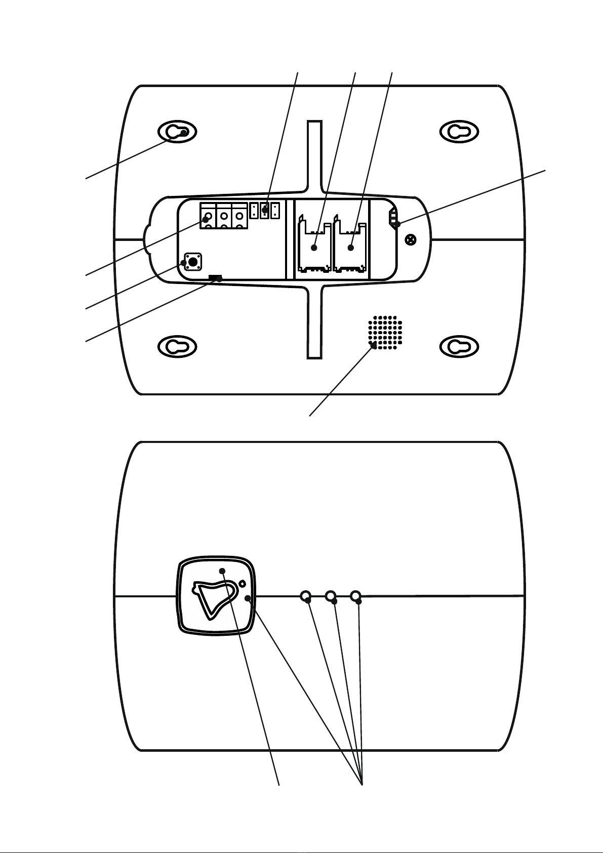
5. Designation of Elements
1
2
3
4
9
8
10 11
5
6
7

5
№Element Designation
1 Fixing holes 4 holes for fixing to surface
2 +12V, GND, SIREN
Terminals for connecting power supply and
wired siren:
+12V – power supply “plus” (if using
external power supply 12V);
GND – power supply “minus” (if using
external power supply 12V) and “minus” of
the siren;
SIREN – «plus» of the siren.
3 SA1 Tamper button
4 Connector for power adapter Connect the power adapter (included in scope of
delivery)
5 JMP 1, 2, 3 Connectors for jumpers
6 SIM1 Main SIM-card
7 SIM2 Redundant SIM-card
8 Location for the battery Connector for battery BL-5C connection
(included in scope of delivery)
9 Buzzer Audible signals (see paragraph 6)
10 Button
When clicking an alarm event is generated
(see section 7)
11 Indicators
Light indication of the panel basic parameters
(see section 6)
6. Indication
The device has 4 visual (blue) indicators at its front panel.
To turn on the visual indication and the audio signal (buzzer), configure their operating
modes in the configuration software. The following visual indication settings are available:
Device power supply status;
Availability of unsubmitted events;
Device registration in GSM network;
Status of sensors in one area.
Audio indication:
Successful registration in GSM network;
Incoming call;
Input delay;
Output delay;
Alarm in area;
7. Panic button
Panic button. Creates an event that is recorded into the device history
and transmitted over configured data links. The event code is specified
in the configuration software. Inactive by default.
6
8. Configuration and Getting Ready for Operation
1. To configure the device, connect to it using the most suitable way:
Desktop configuration. To connect use a Wi-Fi network and the configuration
software ritm.conf or Ritm Configure.
Remote configuration via digital GSM. To connect use a GSM CSD channel and
the configuration software ritm.conf or Ritm Configure.
Remote configuration via TCP/IP. Using the GEO.RITM or RITM-Link software via
a TCP/IP connection.
To use the configuration software ritm.conf or Ritm Configure download it
from the website of the “Ritm” (www.ritm.ru/en) and install all the required
drivers.
To connect via a digital CSD-channel make sure there is access to the
digital data transmission service (CSD) and there are enough funds on the
account of the SIM-card inserted into the device.
Remote configuration via CSD is only possible from the engineering phone
numbers.
2. Do not place the device in the vicinity of EMI sources, large metal objects and
structures, power cable runs. The device installation location should have a strong
GSM signal. Use the template (provided in the package) to mark mounting points on
the wall.
3. Open the cover on the back of the device enclosure.
4. Prior to inserting a SIM card (two SIM cards can also be used) into the device, insert
it into a mobile phone. Turn off the PIN code entry feature, check availability of data
links that are to be used, and check if the SIM card account balance is positive.
Perform the same actions to the second SIM card (if used).
5. Extract the SIM card from the phone and insert it into the SIM1 box (the main SIM
card) (the second/backup SIM card should be inserted into the SIM2 box). Insert SIM
cards only when the device power is off.
6. Connect the power source from the device package to the round connector. A third
party power source may be used (connected to the +12 GND terminals).
7. If necessary, connect the siren to the terminals SIREN and GND.
8. Install the BL-5C battery (above the SIM card boxes).
9. Turn on the device.
10. Connect to the device using a Wi-Fi network or using an object card of a GEO.RITM
monitoring system and set up the device. To connect via Wi-Fi network, switch the
device in access point mode: close the connector JMP2 with a jumper and connect
to the network «RITM-last 8 digits of IMEI». In the connection wizard, specify:
Connection type: IP-direct connection to a device;
IP address: 192.168.4.1;
Port: 53462.
11. After the configuration, remove jumper JMP2. By default, the device stores data
links configured for transmission of data to a GEO.RITM monitoring system.

7
To connect to the device via Wi-Fi for the first time load the device
configuration software to the local PC and then connect to the access
point.
12. Add radio channel devices to the system using either of the two methods:
In the configuration software (see User Manual on www.ritm.ru/en);
Using a jumper. To add devices, close the connector JMP1 with a jumper.
Indication on the sensor indicates that a new device has been added to the
system. After you have added a device, open the JMP1 connector (remove the
jumper).
13. For more information on radio channel operating modes, please refer to device data
sheets.
14. If data links are not configured, the device operates on a SIM card that was first able
to register on the network (for communication with the device over the CSD channel
during remote configuration).
15. Make sure the tamper spring is installed and close the device cover.
16. For information on using of the device in the GEO.RITM mobile and fixed object
monitoring system and its configuration using an object card, please see the Contact
GSM-14 operation manual.
9. Control from your mobile device
The device supports remote control of areas (removal and arming) with the application
Ritm Control2. Control is done using user codes that are defined in the program settings.
10. Hardware Reset of The Access Point
To reset access point settings to the factory default value, successively install JMP3,
and then JMP2.
The network will be reset to the open «RITM-last 8 digits of IMEI».
11. Maintenance and Safety Measures
At least once per month check SIM card accounts for funds.
All setup and maintenance activities applied to the device should be performed by duly
qualified personnel.
12. Transportation and Storage
The device should be transported in packaging in closed vehicles. Storage premises
should be free of current-conducting dust, acid and alkaline fumes, corrosive gases and
gases harmful to insulation.
2The app is available in Google Play. For sharing, the device and the mobile device must be on the
same subnet.

8
13. Manufacturer’s Warranties
The manufacturer guarantees that the device complies to requirements of the technical
specifications, provided the client ensures compliances to conditions of transportation,
storage, installation and operation.
Although the warranty period is 12 months from the commissioning date, it may not
exceed 18 months from the production date.
The warranty storage period is 6 months from the production date.
The manufacturer’s warranty does not cover the battery.
The manufacturer shall not be responsible for quality of data links provided by GSM
operators and Internet service providers.
The manufacturer reserves the right for modification of the device in any way that does
not degrade its functional characteristics without prior notice.
14. Information on Claims
In case of a device failure or defect during the warranty period, please fill in a
malfunction report specifying the dates of issue and commissioning of the device and
nature of the defect and submit it to the manufacturer.
22.05.2018
Table of contents
Other ritm Control Panel manuals


Popular Control Panel manuals by other brands


Fire-Lite
Fire-Lite MS-9600 user manual

GE Intelligent Platforms
GE Intelligent Platforms QuickPanel IC754CBF12CTD Operator Interface Products

HIK VISION
HIK VISION AX Series manual

Pro-face
Pro-face GP-4100 series installation guide

HIK VISION
HIK VISION KH6 Series Configuration guide

HIK VISION
HIK VISION DS-PK-LRT User manual & operation command


