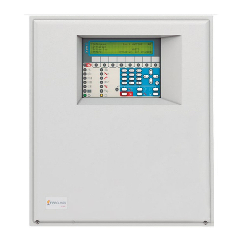
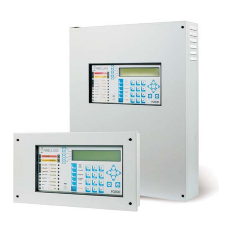
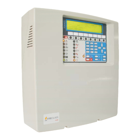
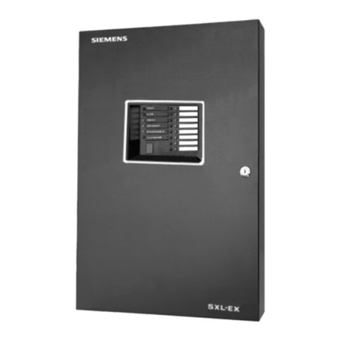
FireClass FC600 User manual

Installation Guide
120.515.930_FC-FC600-P-I
Doc. version 2.0
24. March 2021
FIRECLASS
FC600 Series
Panels and
Repeaters

© 2021 Johnson Controls. All rights reserved. All specifications and other information shown were current as of doc-
ument revision date and are subject to change without notice.
Tyco Fire & Security GmbH, Victor von Bruns-Strasse 21, 8212 Neuhausen am Rheinfall, Switzerland

FireClass Panels and Repeaters Contents
Installation Guide Doc. version 2.0 3
Contents
1 Introduction ............................................................................................................................4
1.1 Keywords and symbols ........................................................................................................................ 4
1.2 Who this manual is for .......................................................................................................................... 4
1.3 What this manual does not cover........................................................................................................ 4
2 Installation notes ...................................................................................................................5
3 Safety warnings .....................................................................................................................5
4 FireClass FC600 series panels ..............................................................................................5
4.1 Optional mounting plate ....................................................................................................................... 6
4.2 Mounting a FC600 series panel to the wall without a mounting plate............................................ 6
5 Inter-unit cabling ................................................................................................................. 11
5.1 Connecting the mains cable and protective earths in FC600 series panels and AC repeaters ..11
6 Loops installation................................................................................................................ 14
6.1 Running and temporarily connecting the loops ..............................................................................14
6.1.1 Interface conventional detectors .............................................................................................................15
6.2 Making insulation checks ..................................................................................................................15
6.3 Wiring the remaining modules ..........................................................................................................15
6.4 Measuring loop resistance .................................................................................................................15
6.5 Connecting the loops fully .................................................................................................................15
7 Installing the batteries .......................................................................................................16
8 Mounting CUI repeater panels........................................................................................... 17
8.1 Connecting the CUI repeater DC supply cabling .............................................................................17
8.2 Connecting the CUI repeater RBus wires .........................................................................................17
9 Provide installation records............................................................................................... 21
10 Make final checks ............................................................................................................... 21
11 Install the FC-FI/FC-FI-1 - field interface board................................................................. 22
11.1 Local FC-FI/FC-FI-1board connections ..............................................................................................23
11.2 Connecting local sounders.................................................................................................................23
11.3 Connecting supervised inputs ...........................................................................................................24
11.4 Checking the FC-FI/FC-FI-1 connections...........................................................................................25
11.5 FC-FI/FC-FI-1 switches and jumper positions ...................................................................................26
11.6 Jumper and DIP switch settings........................................................................................................26
11.6.1 Configuration of a FC600 series panel RBus interface ............................................................................27
11.7 Changing a fuse on the FC-FI/FC-FI-1 ................................................................................................30
12 Installing optional boards, cards and modules................................................................ 31
12.1 Obtaining card addresses...................................................................................................................32
12.2 Card arrangement planning ...............................................................................................................32
12.3 Mounting cards and boards on a FC600 series panel......................................................................32
13 Installing the PNI800 - Panel Net Interface ...................................................................... 32
13.1 Changing a fuse on the PNI800..........................................................................................................35
14 Mounting a FB800 15WAY fuse board on a FC600 series panel.................................... 36
14.1 FB800 15WAY fused 24V outputs board details..............................................................................36
15 Binary DIP switch lookup table ......................................................................................... 37

FireClass Panels and Repeaters Introduction
Installation Guide Doc. version 2.0 4
1Introduction
Use this guide as a source of useful information when
installing a FireClass FC600 series alarm system.
The guide sets out a recommended series of steps to
follow.
Not all the steps are covered in detail, as this would be
beyond the scope of the guide, and these details are
provided in other documentation (see also “What this
manual does not cover”) below. Rather, the guide pro-
vides an overall sequence and context for the installa-
tion.
1.1 Keywords and symbols
In this manual symbols are used in the margin to indi-
cate warnings, and also ‘hints and tips’ type informa-
tion.
These are explained in Table 1.
1.2 Who this manual is for
This guide is aimed at suitably qualified technicians who
have received training and are experienced in the instal-
lation of fire detection and alarm systems.
1.3 What this manual does not
cover
The guide does not provide information on the follow-
ing:
System design.
The system must already be designed and planned
for the specific site, in terms of cable routing, device
selection and layout, mains supply etc.
For more information, see the FireClass FC600
Series Product Application and Design Information
guide. This includes details of optional modules that
can be fitted.
Local regulations.
For example cable specifications and panel siting
restrictions are expected to be covered by local
regulations. Because these factors need to be incor-
porated into the design, they are excluded from this
guide.
Local regulations are expected to cover, for
example:
– Wiring specifications
– Panel siting restrictions
– Provision for mains isolation
– Earthing arrangements
– Environmental conditions
– Qualifications of personnel.
For example there may be a stipulation that the
connections for the mains supply and protective
earth can only be made by a qualified electrician.
Installation of detector bases and ancillaries.
Refer to the respective installation (wiring) instruc-
tions.
Installation of optional modules.
These products have their own specific instructions;
however this guide does provide supplemental
information for installation in the FireClass FC600
series panel where necessary.
Procedures covered by another of the guides are
available for the FireClass FC600 fire panel range.
For example in the FireClass FC600 Panels Commis-
sioning Instructions, there are various tests to be
performed using operator functions as described in
the FireClass FC600 User Manual.
Keyword Symbol Explanation
DANGER Warning.
Imminent danger.
Death or severe injury
when disregarded.
WARNING Warning.
Potentially dangerous
situation.
Death or severe injury pos-
sible when disregarded.
CAUTION Warning.
Potentially dangerous
situation.
Minor injury possible
when disregarded.
NOTICE Warning.
Potentially dangerous
situation.
Material damage possible
when disregarded.
Helpful information.
Table 1: Keywords and symbols in this documentation

5Installation Guide Doc. version 2.0
Installation notes FireClass Panels and Repeaters
2 Installation notes
There is a section of installation notes in the FireClass
FC600 Panels Product Application and Design Informa-
tion guide. Check these for information possibly affect-
ing your installation, such as the arrangement of multi-
ple stacked cards.
3 Safety warnings
4 FireClass FC600
series panels
The FireClass FC600 range consists of the following
panels:
FC602S.
This is a two loop FireClass panel with a shallow
housing. This panel can have two standard power
loops or one high power loop with a maximum of
250 addresses. It features a colour LCD display with
32 zonal LEDs. The panel has a compact housing and
a BAW75T24 PSU for 17AH batteries. The FC602S
is a networkable panel.
FC604S. This is a four loop FireClass panel with a
shallow housing. This panel can have four standard
power loops or two high power loops with a maxi-
mum of 500 addresses. It features a colour LCD dis-
play with 32 zonal LEDs. The panel has a designer
housing and BAQ140T24 PSU for 17AH batteries.
The FC604S is a networkable panel.
FC602S Scandinavian. This is a two loop FireClass
panel with a shallow housing. This panel can have
two standard power loops or one high power loop
with a maximum of 250 addresses. It features a col-
our LCD display with 32 zonal LEDs. The panel has a
compact housing with a fireman’s keyswitch and a
BAW75T24 PSU for 17AH batteries. The FC602S
Scandinavian is a networkable panel.
FC604S Scandinavian. This is a four loop FireClass
panel with a shallow housing. This panel can have
four standard power loops or two high power loops
with a maximum of 500 addresses. It features a col-
our LCD display with 32 zonal LEDs. The panel has a
compact housing with a fireman’s keyswitch and
DANGER
The FireClass Panel contains high
voltages, producing a danger of death or
serious injury while working on the
panel.
Note the dangerous voltage warning
sticker on the PSU.
Follow all steps and note all warnings in
this guide relating to electrical safety
and earthing.
Fig. 1:Screws and wall plugs (the screws are approximately
63mm long)

FireClass Panels and Repeaters Optional mounting plate
Installation Guide Doc. version 2.0 6
BAQ140T24 PSU for 17AH batteries. The FC604S
Scandinavian is a networkable panel.
4.1 Optional mounting plate
The FC600 series panels are not supplied with a mount-
ing plate. Mounting plates are available to
purchase using part number 557.202.921. They can be
used with all panels except for DC Repeaters. See Fig-
ures 2 and 3.
4.2 Mounting a FC600 series
panel to the wall without a
mounting plate
For an overview of the panel, see Fig. 4. To mount a
FC600 series panel without the optional mounting plate,
complete these steps:
1 Decide on a wall mounting method (typically screws
into rawl plugs), and assess the required sizes of the
fastenings. Take into account the type of wall (solid
brick, wood and so on), and the weight of the assem-
bled control panel housing.
2 For the upper mounting holes, mark on the wall the
drill hole positions. Drill and plug the holes.
3 Insert screws to suspend the housing from the
upper holes. The housing may feature “keyholes” to
allow you to insert the screws into the bare wall,
then drop the housing onto the screws (rather than
screwing with the housing in position, through the
back wall.
4 Ensure the housing is horizontal. For the lower
mounting holes, mark on the wall the drill hole posi-
tions. Drill and plug the bottom fixing holes. Insert
screws to complete fixing the housing to the wall.
5 Check the housing is physically secure.
6 Remove any debris from the housing.
Fig. 2: Optional mounting plate 557.202.921, available to
purchase.

7Installation Guide Doc. version 2.0
Mounting a FC600 series panel to the wall without a mount- FireClass Panels and Repeaters
240
149.5
140
7527 378

480
330
410
40 40
85 85
Fig. 3: FC602S/FC604S panel, FC602S/FC604S Scandinavian panel, and the FC32AR/FC32AR AC Scandinavian repeaters
mounting with a universal mounting plate - fixing and overall dimensions in mm

FireClass Panels and Repeaters Mounting a FC600 series panel to the wall without a mounting plate
Installation Guide Doc. version 2.0 8
Fig. 4: FC602S and FC604S panels with shallow housing, and the FC32AR AC repeater - overall dimensions in mm
480
410
140
35
50

9Installation Guide Doc. version 2.0
Mounting a FC600 series panel to the wall without a mount- FireClass Panels and Repeaters
Fig. 5: FC602S/FC604S Scandinavian panel - overall dimensions in mm
480
410
140
35
50

FireClass Panels and Repeaters Mounting a FC600 series panel to the wall without a mounting plate
Installation Guide Doc. version 2.0 10
370
80
50
254
3
Fig. 6: FC32DR DC repeater - overall dimensions in mm

11 Installation Guide Doc. version 2.0
Inter-unit cabling FireClass Panels and Repeaters
5 Inter-unit cabling
5.1 Connecting the mains cable
and protective earths in
FC600 series panels and AC
repeaters
NOTICE
There is a danger of signal interference
between cable runs.
Take care when laying out transmission
lines to avoid the potential for cross-
coupling between them.
370
254
80
3
50
Fig. 7: FC32DR DC Scandinavian repeater - overall dimensions in mm
DANGER
Danger of death or serious injury.
Before working on the Mains
connection, verify that the cabling is not
live. Ensure the cabling is not connected
to the supply, or that the supply is
isolated.

FireClass Panels and Repeaters Connecting the mains cable and protective earths in FC600 series panels and AC repeaters
Installation Guide Doc. version 2.0 12
To connect the Mains cable and protective earth,
complete the following steps:
1 Make sure the Mains cable is not connected to the
supply, or that the supply is isolated.
2 On the PSU, locate the Mains connector at the top
of the unit. If the protective cover is fitted to this con-
nector, remove it.
3 Connect the Mains cable to its connector. Fix the
Mains cable using the clip near the Mains connector.
4 Connect the protective earth conductor of the Mains
to a terminal of the housing earthing point.
5 Particularly in harsh environments, it may be neces-
sary to connect an additional low resistance earth-
conductor to the solid earth bar in the closest distri-
bution unit (stranded wire > 2.5 mm2).
NOTE: Earthing through the mains distribution may
not provide the best path for HF currents.
NOTE: Most AC power distribution systems will
include a low impedance protective earth; however
IT power distribution systems either have no earth
or high impedance to earth. In these cases, a local
low impedance protective earth is required.
6 Re-fit the PSU Mains connector cover.
7 Make sure system 0 V is not connected to the earth,
as there is an earth fault monitoring circuit.
DANGER
The FireClass panel contains high
voltages, producing a danger of death or
serious injury.
You must ensure adequate earthing of
the system.
In addition to any earthing requirements
in the local regulations, additionally you
must, also follow these stipulations:
All exposed metalwork and cabling
conduits must be returned to earth at
the control panel.
The control panel housing must be
earthed, following the procedures as
mentioned in this guide.
WARNING
Particularly in harsh environments, to
ensure proper operation of the control
panel, a second earth, separate from
the mains lead earth, must be installed.
This is described in the following
section.
Fig. 8: PSU Mains Connector Cover (detail)
1–Cover
2– PSU Mains connector

13 Installation Guide Doc. version 2.0
Connecting the mains cable and protective earths in FC600 FireClass Panels and Repeaters
Fig. 9: PSU Mains connections on FC602S/FC604S panel, FC602S/FC604S Scandinavian panel, and FC32AR/FC32AR AC
Scandinavian repeaters
1– Thermistor assembly
2– Cable tie
3– PSU Earth wire

FireClass Panels and Repeaters Loops installation
Installation Guide Doc. version 2.0 14
6 Loops installation
As detailed below, the procedure is to install the loops
into the building, making temporary wiring arrange-
ments for testing. Then, once testing has been com-
pleted, the final loop connections can be made.
6.1 Running and temporarily
connecting the loops
1 Run the loop wiring around the building, and wire in
the bases, according to the system plan. Similarly,
run any other wiring required for ancillary modules.
Clearly label the loop conductors as being positive or
negative.
At this stage, do not wire in any isolator bases, or
other modules, or fit the detectors. This is to avoid
potential damage caused by the high voltage insula-
tion checks. Use strip connectors (Fig. 11) for any
temporary connections, to preserve continuity.
For connection details see the individual leaflets or
labels provided with the products.
2 At the control panel, feed the loop cables through
the appropriate knockouts. Use suitable cable glands
as needed. To maintain IP30 pass test status, use a
58 58294
40 40330
47 21412
Fig. 10: FC32AR/FC32AR AC Scandinavian repeaters without mounting plate - fixing and overall dimensions in mm

15 Installation Guide Doc. version 2.0
Making insulation checks FireClass Panels and Repeaters
M20 cable gland with a locknut. Leave generous
tails of wire (approximately 600 mm length).
3 Connect the loop wiring tails to a strip type connec-
tor block, with screw terminals, as shown in Fig. 11.
Leave the wiring loose within the panel.
4 Ensure that the loop screens and metal sheath are
not connected to the addressable loop conductors
and are left floating relative to earth.
6.1.1 Interface conventional detectors
If necessary, use a FC410DIM or FC410DDM interface
unit to interface conventional detectors on a loop spur.
For details refer to the documentation for the FC410-
DIM or FC410DDM unit.
6.2 Making insulation checks
1 Note that a record should be made of the measure-
ments below, to be handed over to the customer.
2 Ensure your insulation checks will be at 500 V (set
your meter accordingly).
3 Make the usual insulation measurements. For exam-
ple measure the resistance between the two wires
of the loops, and the resistance between the loop
wires and earth.
4 For values less than 1 MOhm this is a failure and the
panel will not operate. In this case investigate and
correct the problem.
5 For values between 1 MOhm and 30 MOhm, inves-
tigate and try to increase the resistance value to
30 MOhm.
6.3 Wiring the remaining
modules
At this stage, wire the remaining modules and isolator
bases into the loops.
6.4 Measuring loop resistance
1 Note that a record should be made of the measure-
ments below, to be handed over to the customer.
2 Make the usual loop positive resistance measure-
ments.
3 Check whether the values are acceptably close to
the anticipated values calculated at the design stage.
4 Remove the temporary connections that you had
made to the connector block. Refer to Fig. 11.
6.5 Connecting the loops fully
1 Wire the loop wires into their connectors. Refer to
Fig. 12.
For the pin-out details, use labelling for the loop con-
nections on the board. The loops are connected to
the FC-FI or the FC-FI-1 board depending on the
panel. The FC602S and the FC602S Scandinavian
use a FC-FI-1; the FC604S and the FC604S Scandi-
navian use a FC-FI board.
2 Plug the connectors to their board sockets.
Fig. 11: Temporary Loop Connection
The dashed lines represent loop wiring
NOTICE
There is danger of damage to equipment. Before
using a high-voltage insulation tester, ensure that
no devices liable to be damaged are fitted to the
circuit. This includes isolator bases and ancillary
modules.
Fig. 12: Loop Wire Connector

FireClass Panels and Repeaters Installing the batteries
Installation Guide Doc. version 2.0 16
7 Installing the
batteries
Note: FireClass FC600 series panels do not have a
separate battery box.
1 Connect the battery cables to the terminals marked
XT10 BAT+ and BAT- on the FC-FI/FC-FI-1 board.
Connect the red cable to positive and the black cable
to negative.
2 Place the batteries at bottom of the control panel
housing.
3 Connect the battery cables to the battery +ve to -ve
terminals.
4 Locate the Fuse Kit in Line (refer to Fig. 13). From
the kit, remove the fuse and keep this safely (you
will be inserting the fuse later as part of the commis-
sioning procedure). Connect the remaining battery
terminals using the kit.
5 Identify the temperature compensation thermistor
lead. Connect the thermistor to terminals labelled
XT10 TEMP on the FC-FI/FC-FI-1 board. Tape this
thermistor and the thermistor from the mains PSU
(see Fig. 9) at the end of the lead, at a convenient
location on the top of a battery.
6 Re-fit the battery fuse.
7 Label the batteries with the current date.
DANGER
The standby batteries can deliver high
current, producing a danger of injury and
equipment damage while working on the
panel.
Take care not to accidentally short the
battery terminals, especially when fitting
the retaining bracket. The batteries are
supplied charged.
Battery variations
Your batteries may differ from the ones
shown in the illustrations below (which are
POWER SONIC 17 AH batteries).
Fig. 13: Battery in-line fuse kit
WARNING
The standby batteries can deliver high
current, producing a danger of injury
and equipment damage while working
on the panel.
Take care not to accidentally short the
battery terminals, especially when
fitting the retaining bracket.
The batteries are supplied charged.
Note
The battery must be of the VRLA type
(valve regulated lead acid).
The battery must have an enclosure with
flammability class UL94V-1 or better.
The battery must comply with all applica-
ble standards indicated in paragraph M.2.1
of standard EN 62368-1:2014 “Require-
ments (safety of batteries and their ele-
ments)”; in this case, the standards: IEC
60896-21:2004 and IEC 60896-22:2004.
The battery must be replaced by a skilled
person.

17 Installation Guide Doc. version 2.0
Mounting CUI repeater panels FireClass Panels and Repeaters
8 Mounting CUI
repeater panels
Complete the instructions in the following sections to
mount a FC32DR DC colour user interface (CUI)
repeater. For FC32AR repeaters, see section 5.1, “Con-
necting the mains cable and protective earths in FC600
series panels and AC repeaters” on page 11.
8.1 Connecting the CUI repeater
DC supply cabling
DC colour user interface (CUI) repeaters are powered
from the control panel. To connect the repeater DC
supply cabling, complete the following steps:
1 Identify suitable DC supply wire. Strip off the
insulation to leave a few millimetres of bare wire
ends.
2 At the control panel feed the wire into the housing
through a suitable knockout, using a gland if
necessary.
3 Note which colour conductor is connected to which
terminal on the panel to the 24V & 0V.
4 At the CUI repeater feed the supply cable through a
suitable knockout, using a gland if necessary.
5 At the CUI repeater there are two RBUS
connections, RBUS_L and RBUS_R, which are left
and right channels. Connect the 24V & 0V to the
appropriate terminal block.
6 For the RBUS_L use terminal blocks TB1 & TB2 and
RBUS_R use terminal blocks TB3 & TB4. As shown
in Table 2.
For the locations of the terminal blocks on the CUI
repeater, see items 1 to 4 in Fig. 13.
7 Connect the 24V & 0V to the appropriate terminal
blocks on the CUI repeater, matching the colours to
the terminals.
8.2 Connecting the CUI repeater
RBus wires
1 Wire the "control panel end" of the RBus wires into
their connector, XT1 on the FC-FI labelled LEB/
RBUS, A, B and GND. The connector is similar to the
loop connector.
2 Feed these wires out of the control panel through a
suitable knockout using a gland if necessary.
3 For RBUS_L use terminal blocks TB1 and TB2. For
RBUS_R use terminal blocks TB3 andTB4, as shown
in Table 2.
4 Double-check whether an EOLR resistor needs to be
fitted. There are links on the CUI repeater to add
120R termination on the RBUS. Link pins 2 and 3 on
the 3-pin connectors CON5 & CON6 to add this
PCB label Function
TB1 RBUS Left connections
for repeater CUI
Pin1 - CHASSIS
Pin2 - 0V
Pin3 - +24V DC
Table 2: Terminal block information
TB2 RBUS Left connections
for repeater CUI
Pin1 - RS485 NET REF
Pin2 - RS485 B
Pin3 - RS485 A
TB3 RBUS Right connections
for repeater CUI
Pin1 - CHASSIS
Pin2 - 0V
Pin3 - +24V DC
TB4 RBUS Right connections
for repeater CUI
Pin1 - RS485 NET REF
Pin2 - RS485 B
Pin3 - RS485 A
PCB label Function
Table 2: Terminal block information

FireClass Panels and Repeaters Connecting the CUI repeater RBus wires
Installation Guide Doc. version 2.0 18
resistance or no links equates to no additional
termination resistance.
5 At the CUI repeater, feed the RBus wires through
the appropriate knockout, using glands as
necessary.
6 Connect the RBus wires to the appropriate terminal
block connector, dependent upon if it's a left or right
RBUS connection, TB2 or TB4. Connect the RS485
A and B signals for the RBUS.
7 Connect the RBus cable screen to the housing earth
connector. (Do not earth the screen at the repeater
end, it must only be earthed at one end.)
8 Check whether an isolator IC needs to be fitted to
the CUI repeater.
Note: The need for an isolator must be established at
the system design stage, so check whether an isolator
IC has been included in the equipment consignment. In
general, an isolator IC is fitted to all AC powered repeat-
ers. The isolator provides protection when there may be
different mains supply or ground reference voltages at
the control panel, compared to these voltages at the
CUI repeater. This may occur if there is a large distance
between the panel and CUI repeater.
9 If you need to fit an isolator IC, fit a DC-DC Converter
to socket SK1 on the CUI Repeater, 125.013.520.
10 When you fit the DC-DC converter, make sure that
the LK3 & LK4 links on the CUI repeater are not
linked.
11 Set the address and baud rate using the DIP switch
S1 on the CUI Repeater. Make the baud rate setting
according to Table 4. Make the address setting
according to Table 3. For the address, set the switch
to OFF for binary 0, or ON for binary 1. The DIP
switch S1 location is on the top left-hand side, see
items 1 to 4 in Fig. 13. You may use a small screw-
driver to move the switch sliders.
12 S1-8: Processor Fault Sensing option.The Default
position is OFF (disabled) for normal operation. Only
set ON if required to generate a “local” processor-
fault for any fault condition on the panel. Legacy-
function for old hardware.
Binary Switch Position
Address 1 2 3 4
1 ON OFF OFF OFF
2 OFF ON OFF OFF
3ONONOFFOFF
4 OFF OFF ON OFF
5 ON OFF ON OFF
6 OFF ON ON OFF
7 ONONONOFF
8 OFF OFF OFF ON
9ONOFFOFFON
10 OFF ON OFF ON
11 ON ON OFF ON
12 OFF OFF ON ON
13 ON OFF ON ON
14 OFF ON ON ON
15 ON ON ON ON
Table 3: Repeater address setting
Baud Rate DIP Switch
position 5
DIP Switch
position 6
4800 ON OFF
9600 OFF ON
19200* ON ON
Table 4: Repeater baud rate setting
*Default

19 Installation Guide Doc. version 2.0
Connecting the CUI repeater RBus wires FireClass Panels and Repeaters
Fig. 14: FC32DR/FC32DR DC Scandinavian repeaters mounting - overall fixing dimensions
1– Mounting hole
2– Knockout
370
370
290 4040
254
254
127
80
3x 6.7
174 40

FireClass Panels and Repeaters Connecting the CUI repeater RBus wires
Installation Guide Doc. version 2.0 20
Fig. 15: CUI - Colour User Interface (557.202.919)
1– TB1
2– TB2
3– TB3
4– TB4
5– DC-DC converter position (If used for repeater.Plug into socket SK1 for repeater version).
6– Link L3 fit 2-3 if no DC-DC converter
7– Link L4 fit 1-2 if no DC-DC converter
8– X900 - 20 way ribbon cable connection to FC-FI/FC-FI-1
9– X204 - Boot-mode link. Link 1-2 normal run mode. Link 2-3 bootloader mode.
10–X200 - Watchdog link. Link 2-3 normal run mode. Link 1-2 watchdog disabled mode.
11–Zonal LEDs
12–Keyswitch
13–CON6 - 120R termination on RS485 comms. Link 2-3 to add 120R termination.
14–CON5 - 120R termination on RS485 comms. Link 2-3 to add 120R termination.
15–S1 DIP switch - Used to set the RBUS address and Baud rate. 1-4 RBUS Address. 5-6 Baud Rate select. 7-8 Future Use
Other manuals for FC600
1
Table of contents
Other FireClass Control Panel manuals

FireClass
FireClass DUO-CEL User manual

FireClass
FireClass FC503 User manual

FireClass
FireClass FC501 Series User manual

FireClass
FireClass FC-P-S Installation and user guide

FireClass
FireClass FC503 Owner's manual

FireClass
FireClass Precept EN Panel User guide

FireClass
FireClass 500 User guide

FireClass
FireClass FC501-L Technical manual

FireClass
FireClass FC503 User manual

FireClass
FireClass FC32-1 Owner's manual