ritm Voyager 2N User manual

St Petersburg, 2017
GPS/GLONASS tracker
Voyager 2N
Operating Manual.
Rev. 1.3

www.ritm.ru 2of 173
Operating Manual. Voyager 2N
Table of Contents
Introduction 5
Device Overview 6
Designation and Principle of Operation 6
Specications 8
ATOL, ARI, 3G and Wi-Fi Versions of Voyager 2N 8
LIGHT and LIGHT RS-485 Versions of Voyager 2N 9
Design 10
Voyager 2N 10
Voyager 2N Wi-Fi 12
Voyager 2N ARI 14
Voyager 2N ATOL 16
Voyager 2N LIGHT 18
Voyager 2N LIGHT RS-485 20
Indication 22
GPS/GLONASS reception indicator 22
SIM card reception indicators 23
Power indicator 23
Delivery Package 23
Intended Use 24
Operating Limits 24
Unpacking Tracker 24
Visual Inspection 24
Getting Ready for Operation 25
Monitoring Server Data 25
GSM Package Selection 25
SIM card Insertion 26
Battery Installation 26
Power On 27
Tracker Operation 28
Supported Devices and Interfaces 29
Tracker Setup 30

www.ritm.ru 3of 173
Operating Manual. Voyager 2N
Accessing Conguration Software 30
Conguration over USB Cable 30
Conguration over CSD 32
Conguration via GEO.RITM 33
Conguration via RITM-Link 34
Setup utility 35
Device Details 37
Date and Time 39
Operation Modes 41
SMS-messages 46
Track 50
A-GPS 53
Sensors 55
Counters 67
Input terminals 69
Output terminals 73
Indication 75
Communication channels 77
Coordinate Receipt Servers 79
GPRS Parameters 83
Wi-Fi parameters 86
EGTS Parameters 94
EGTS statistics 97
Dispatch 99
Message Terminal 101
History Structure 110
History 112
Engineering Numbers 114
Autoinformer 116
CAN 118
I/O Ports 123
Available Update 127

www.ritm.ru 4of 173
Operating Manual. Voyager 2N
Service 129
Adding to GEO.RITM 132
Tracker Installation on Vehicle 134
Connections 136
Marking and Connection of Connectors 136
20-Pin Connector Pinout 137
Power supply connection 138
Discrete Input Connection 139
Digital Fuel Gauge Unit Connection 140
Omnicomm LLS-AF20160 140
EPSILON ES4 144
Frequency Analog Fuel Gauge Unit Connection 147
Connection to vehicle CAN bus 149
Connection of IRMA MATRIX trafc sensors 150
Connection of dispatch unit 152
Temperature Sensor Connection 154
Touch Memory Reader Connection 155
Tracker Test Procedure 156
Maintenance 158
Safety Precautions 159
Transportation and Storage 160
Manufacturer’s Warranties 161
Disposal Note 162
SMS commands 163
JSON commands 164
Text protocol commands 166
Commands to request current tracker settings 166
Commands to change the settings of the tracker 170

www.ritm.ru 5of 173
Operating Manual. Voyager 2N
Introduction
This operating manual covers Voyager 2N tracker (hereinafter referred
to as the tracker) designed for monitoring of mobile objects and supporting
connection of external devices for fuel level monitoring, connection to
on-board computer, monitoring of operation of mechanisms and alarm
system installed on the vehicle.¹
This manual contains data on the design, principle of operation, tracker
properties, its parts, and guidelines for proper and safe operation of
tracker (intended use, maintenance, storage, and transportation).
This operating manual provides necessary information for preparatory
training and further use of tracker.
This manual covers the following tracker versions:
1. Voyager 2N.
2. Voyager 2N 3G.
3. Voyager 2N Wi-Fi.
4. Voyager 2N ARI.
5. Voyager 2N ATOL.
6. Voyager 2N LIGHT.
7. Voyager 2N LIGHT RS-485.
1) The list of supported features depends on the tracker version.

www.ritm.ru 6of 173
Operating Manual. Voyager 2N
Device Overview
Designation and Principle of Operation
Voyager 2N is a small form-factor device for monitoring of mobile
objects powered from a built-in battery and supporting connection of an
external power source with 12/24 V rated voltage.
A working tracker receives signals from global navigation satellite
systems2GPS and GLONASS in order to determine the location and other
parameters (such as current time, direction of travel, speed, number of
satellites).
The tracker saves messages it generates to the internal memory and
submits them to the monitoring software. Transfer of data to the
coordinate receipt server is done via a GSM cellular communication
channel.
The tracker may operate only provided that an intact, activated SIM card
is used that has not been locked by an MNO and has an activated package
of necessary services (GPRS, CSD, roaming).
Independent power supply from a battery3allows the tracker to be used
as a portable device for monitoring of people, cargoes, and vehicles4.
The tracker is fastened directly to the monitored object.
!
Do not use the tracker in the vicinity of working medical equipment,
on planes and in prohibited locations,as it can generate interference
adversely affecting electronic equipment.
2) Hereinafter referred to as GNSS.
3) For tracker versions featuring a battery.
4) Hereinafter referred to as vehicles.

www.ritm.ru 7of 173
Operating Manual. Voyager 2N
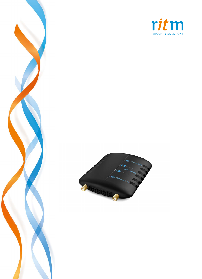
Different tracker versions have their unique distinctions and features.
Such as:
Voyager 2N supports the following features: operation via global
navigation satellite systems GPS and GLONASS, data transfer over a GSM
channel, installation of 2 SIM cards, non-volatile memory, built-in battery
for standalone operation and wide possibilities for external connection of
optional devices enable using the tracker for a wide range of applications:
from basic monitoring to monitoring the condition of key vehicle
assemblies.
The Voyager 2N 3G has all the features of the Voyager 2N version and is
capable of transmitting and receiving data over 3G networks.
The Voyager 2N Wi-Fi has all the features of the Voyager 2N version,
while also being capable of transmitting and receiving data over IEE 802.11
(Wi-Fi) wireless networks, enabling it to serve as an access point for driver
identication, or as a client capable of connecting to wireless networks for
further data transfer and conguration setup via server.
Voyager 2N ATOL is a version completed in a special enclosure enabling
receipt of data from ATOL Drive5 tachographs.
Voyager 2N LIGHT is a cheaper version of the tracker. The device has
one SIM card slot. The device has only one discrete input, which can be
used for connecting a panic button or monitoring limit switches of any
vehicle mechanism.
Voyager 2N LIGHT RS-485 is another cheaper version of the tracker.
Options: installation of 1 SIM card, connection of external devices,
connection of intrusion sensors or mechanism monitoring sensors. The
tracker has one discrete input and one input for connection of a digital fuel
gauge unit with an RS-485 interface.
Voyager 2N LIGHT CAN is a cheaper version of the tracker with the
ability to read CAN-bus of the vehicle.

www.ritm.ru 8of 173
Operating Manual. Voyager 2N
Specications
ATOL, ARI, 3G and Wi-Fi Versions of Voyager 2N
GPS +
GLONASS +
Communication channels
in the GSM network CSD, GPRS
GSM antenna External
GPS/GLONASS antenna External
EGTS protocol data transfer +
3G network data exchange Yes (Voyager 2N 3G version)
Number of SIM cards, pcs 2
Type of SIM cards micro-SIM
PC connection over USB +
Connection to vehicle CAN bus +
Connection of digital fuel gauge units Yes, via RS-232 and RS-485 interfaces
Connection of Touch Memory reader +
Connection of audio actuation device Yes (in ARI Version)
Connection of dispatch unit +
Universal inputs (discrete/
frequency/analog/counter) 2
Discrete inputs 2
Outputs (~ 1 A) 2
External indicators "GPS/GLONASS Reception","SIM1 Reception",
"SIM2 Reception", "External Power"
Built-in motion sensor +
Non-volatile memory, MB 8
Non-volatile memory, No. of entries 150,000
Battery type BL-5C
External supply, V 10–36
Tracker energy consumption, A 0.02–0.15 (depending on mode)
Enclosure Protection Rating IP52 (IP20 for ATOL Version)

www.ritm.ru 9of 173
Operating Manual. Voyager 2N
Enclosure break-in tamper Yes (excluding ATOL Version)
Dimensions, mm 20×80×110
(23×80×108 for ATOL Version)
Weight, g 150
Operating temperature range, °С -40...+85
LIGHT and LIGHT RS-485 Versions of Voyager 2N
GPS +
GLONASS +
Communication channels
in the GSM network CSD, GPRS
GSM antenna Built-in
GPS/GLONASS antenna Built-in
Number of SIM cards, pcs 1
Type of SIM cards micro-SIM
PC connection over USB +
Discrete input 1
Connection of digital fuel gauge units Yes, over RS-485 interface
(for LIGHT RS-485 Version)
External indicators "Test"
Built-in motion sensor +
Non-volatile memory, No. of entries 29,000
External supply, V 10–36
Tracker energy consumption, A 0.02–0.15 (depending on mode)
Enclosure Protection Rating IP52
Dimensions, mm 20×80×110
Weight, g 140
Operating temperature range, °С -40...+85

www.ritm.ru 11 of 173
Operating Manual. Voyager 2N
Part Designation
Tamper button
When the battery compartment cover is opened,
device operating indicators turn on. When the
cover is closed, the indicators are turn off.
USB connector For conguration cable connection.
20-pin connector For connection of power supply and peripherals.

www.ritm.ru 13 of 173
Operating Manual. Voyager 2N
Part Designation
Tamper button
When the battery compartment cover is opened,
device operating indicators turn on. When the
cover is closed, the indicators turn off.
USB connector For conguration cable connection.
20-pin connector For connection of power supply and peripherals.
SIM card 1 box SIM card 2 box
Battery installation
location
Tamper button

www.ritm.ru 15 of 173
Operating Manual. Voyager 2N
Part Designation
Tamper button
When the battery compartment cover is opened,
device operating indicators turn on. When the
cover is closed, the indicators are turn off.
USB connector For conguration cable connection.
Connector for audio
actuation device
For connection of external speaker or
amplier. Required for IVR.
20-pin connector For connection of power supply and peripherals.
microSD memory
card box
SIM card 1 box
Tamper button
SIM card 2 box
Battery installation
location

www.ritm.ru 17 of 173
Operating Manual. Voyager 2N
Part Designation
USB connector For conguration cable connection.
20-pin connector For connection of power supply and peripherals.
Tachograph connector Connector for ATOL Drive5 tachograph.
GPS/GLONASS signal
reception indicator
SIM card 1 operation
indicator
SIM card 2 operation
indicator
Power
indicator
RITM
Voyager 2N-T

www.ritm.ru 19 of 173
Operating Manual. Voyager 2N
Part Designation
“Test” button
Used for waking the tracker up from the sleep mode (turning
on the GPS receiver and the GSM modem), as well as for
switching on/off the GPS receiver operation indicators.
USB connector For conguration cable connection.
20-pin connector For connection of power supply and peripherals.
“Test” button
SIM card box
Table of contents
Other ritm GPS manuals