Ritron RCCR User manual

RCCR
CLEAN CAB LOCOMOTIVE RADIO
Owner’s Manual
Ritron Pub. 14500073 Rev. B 11/05/09
© 2009 Ritron, Inc. All rights reserved. Ritron, Patriot, Jobcom, OutPost, GateGuard, Quiet Call,
Quick Assist, and RadioNexus are registered trademarks of Ritron, Inc. Quick Talk and Liberty
are trademarks of Ritron, Inc.
Call 877-312-4547
For the right Wireless Solutions for your communication needs.

Table of Contents
Introduction .............................................................................................1
OPERATING THE RADIO
Channel Zone Set-Up........................................................................3
AAR Channel Selection ...................................................................4
DTMF Tones ......................................................................................6
Single Tone .......................................................................................7
DTMF or Single Tone Dispatch .......................................................8
Transmit and Busy Indication .........................................................8
Volume ..............................................................................................9
PTT (Push-to-Talk) ...........................................................................9
Brightness Control ..........................................................................9
Home Channel Selection ...............................................................10
Revert to Last TX-RX Channel Pair ..............................................11
Error Messages ..............................................................................11
INVALID .................................................................................11
ANTENNA ..............................................................................11
RADIO CONNECTORS
RCCR Connectors – Rear Panel ...................................................12
RCCR Connectors – Side Panel ...................................................13
RCCR Connectors – Remote Head ...............................................14
PROGRAMMING THE RADIO
Getting Started ................................................................................15
Connecting to the Computer ...............................................15
The Programmer Screen .....................................................15
Programmer Menus
Open File ...............................................................................16
Save File ................................................................................16
Print Radio Data ...................................................................17
Print Custom Frequency Data .............................................17
Print Home Channel Data ....................................................18
Read Radio ............................................................................18
Program Radio ......................................................................19
Update Firmware ..................................................................19
NXDN ......................................................................................20
AAR Frequencies .................................................................20
Help ........................................................................................20
Volume .............................................................................................21
Timers ..............................................................................................22
Options ............................................................................................23
Keypad ............................................................................................24
Radio ID ...........................................................................................25
Home Channels ..............................................................................26
Custom Frequencies ......................................................................28
NXDN ................................................................................................29
Align .................................................................................................30
APPENDIX
RF Exposure Statement .................................................................31
AAR Channels ................................................................................34
RCCR Radio Specifications ..........................................................36
RITRON, Inc. Limited Warranty......................................................38
---------------------------------------------------------------------------------------------------------------
Ritron RCCR Clean Cab User Manual 1
Introduction
The Ritron RCCR radio is designed specifically for Clean Cab locomotive operation and meets all AAR
specifications for fit, form and function. The location of all connectors is consistent with AAR
standards to allow the easy replacement of a Clean Cab radio without re-routing existing cables.
The RCCR radio is available in two models:
RCCR-151 A single-piece radio with the control head attached to the main radio.
RCCR-152 A two-piece radio with the control head detached from the main radio.
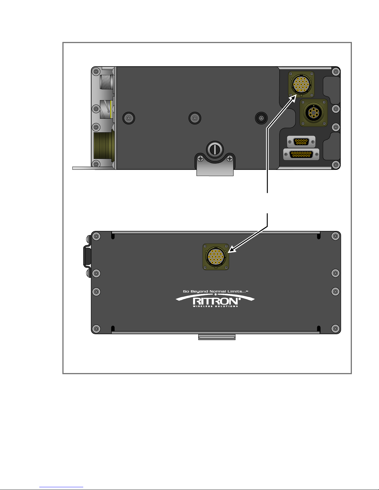
The RCCR-152 control head is connected to the main radio via an AAR standard 19-
pin connector cable. The female mating connector on the main radio can be located
on either the rear or the front of the radio to allow maximum flexibility during
installation. A small plate covers the unused connector location. The male mating
connector is located on the back of the RCCR-152 control head. The control head is
designed to mount in the standard AAR opening in the locomotive throttle stand or
overhead.
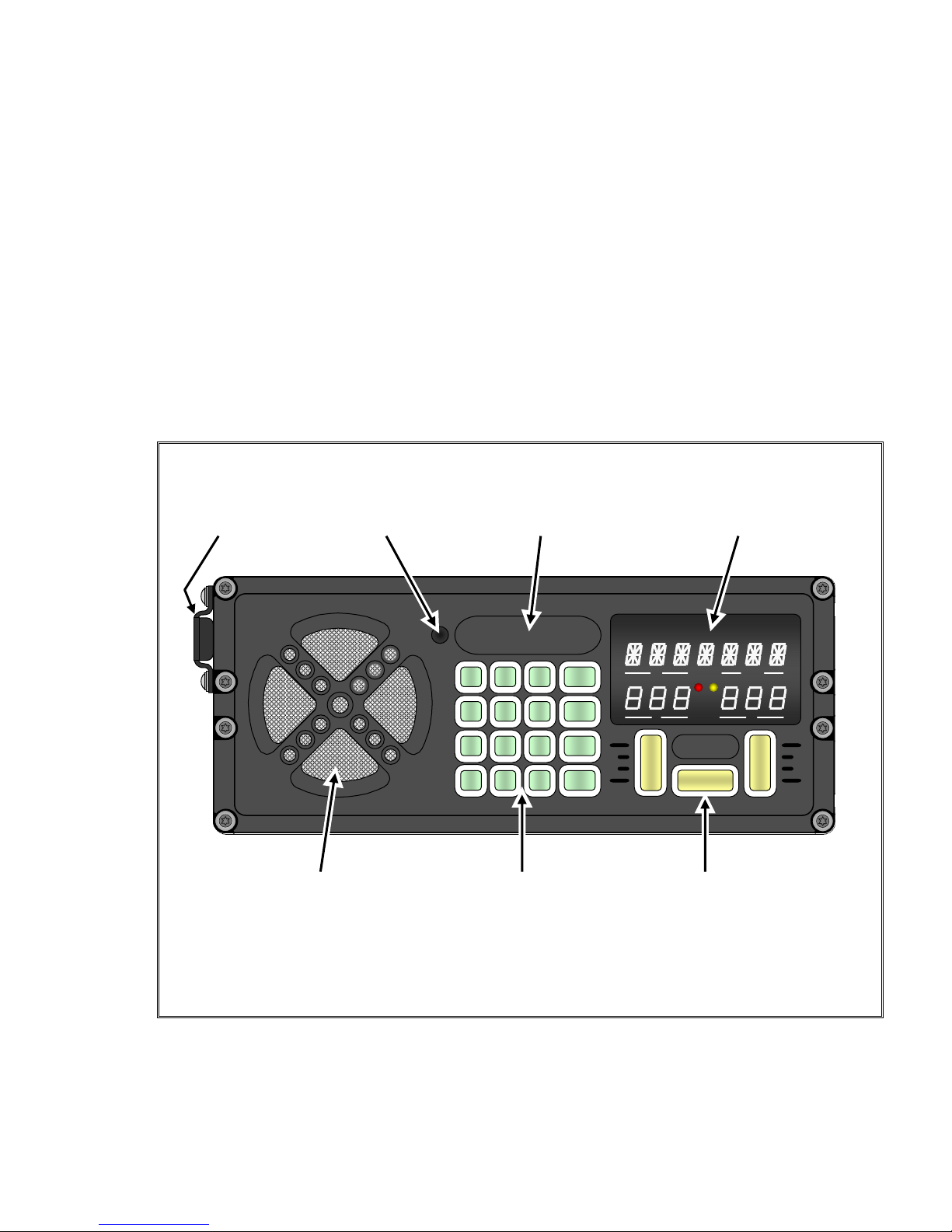
LED display with large white
Carry Front panel Area for ID 0.4” characters, red TX lamp,
strap microphone engraving and yellow Busy lamp
RCCR CONTROL HEAD FRONT VIEW
T
/
DTX RX
TX RX
D
I
S
P
P
T
T
▼VOL▲
»0 #
7 8 9
4 5 6
1 2 3
HOME
TONE
DTMF
CHAN
HOME
Front panel speaker Green illuminated
numeric/function
keypad
Yellow illuminated
control keypad
---------------------------------------------------------------------------------------------------------------
Ritron RCCR Clean Cab User Manual 2
RCCR-152 – RADIO REAR VIEW
The 19-Pin female connector can
be installed in either location.
RCCR-152
–
RADIO FRONT VIEW
DESIGNED & MANUFACTURED IN CARMEL, INDIANA 46032 U.S.A.
WWW.RITRON.COM
800-USA.1.USA
OPERATING THE RADIO
-----------------------------------------------------------------------------------------
---------------------------------------------------------------------------------------------------------------
Ritron RCCR Clean Cab User Manual 3
Channel Zone Set-Up
The RCCR -151 Locomotive Radio can be set-up using the front panel keypad such that any or all of
the available Channel Zones are enabled for normal radio operation. The available zones are:
yHome Channel Zone (1 – 500)
yWideband Channel Zone (AAR03 – 97)
yNarrowband Channel Zone (AAR005 – 097)
yNarrowband Offset Zone (AAR104 – 197)
yDigital Channel Zone (AAR302 – 488)
IMPORTANT!
DO NOT pause more than 2 seconds between keypad presses prior to the completion of set-up,
otherwise the radio will automatically resume normal operation and the operator must begin at Step 1.
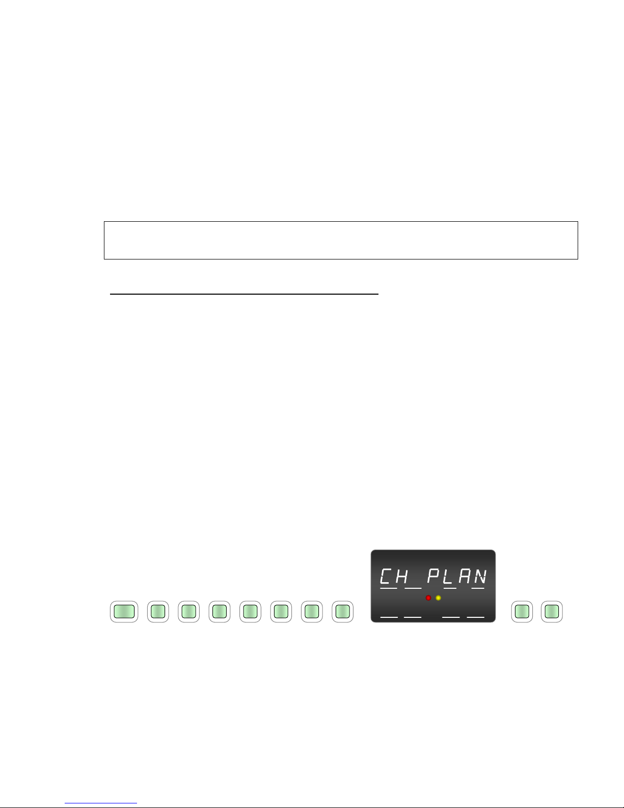
To enable Channel Zones using the front panel keypad:
1. Press CHAN - #- 6– 2– 7 – 7 – 6 - 9
2. “CH PLAN” will be displayed on the top row of the LED Display.
3. Referring the table below, press the keypad digits to enable the corresponding channel zone(s)
you wish to enable.
1 – Home Channel Zone (1 – 500)
2– Wideband Channel Zone (AAR03 – 97)
3 – Narrowband Channel Zone (AAR005 – 097)
4 – Narrowband Offset Zone (AAR104 – 197)
5– Digital Channel Zone (AAR302 – 488)
4. After last digit is pressed, wait 2 seconds and the radio will automatically resume to normal
operation.
5. If a channel from a list that is not enabled is entered using the front keypad, “INVALID” will be
displayed momentarily (2 sec), and then the last valid channel entered will be displayed.
The following example illustrates a Channel Zone Set-Up to enable only the Narrowband Channel
Zone (3) and Digital Channel Zone (5).
T/D HOME
TX RX
TX RX
#627 7 6 9 3 5
CHAN
Press CHAN - # - 6 – 2 – 7 – 7 – 6 – 9 ►CH PLAN is displayed ►Press 3 – 5

OPERATING THE RADIO
-----------------------------------------------------------------------------------------
---------------------------------------------------------------------------------------------------------------
Ritron RCCR Clean Cab User Manual 4
AAR Channel Selection
CHAN
The CHAN button is used in conjunction with the numeric keypad to select AAR channels:
•03 - 97 for Wide Band (25 kHz) operation
•005 - 097 for Narrow Band (12.5 kHz) operation
•104 - 197 for Narrow Band (12.5 kHz), 7.5 kHz Offset operation
•302 – 488 for Digital (6.25 kHz) operation
Refer to chart “AAR Channels” on page 31 for the complete list of AAR frequencies available with the
CHAN button. Note that wide band channels 05-97 are the same frequency as the corresponding
narrow band channels 005-097, only the operating bandwidth is different. 7.5 kHz offset, narrow band
channels 104-197 operate the transmitter and the receiver on a frequency 7.5 kHz higher than the
selected AAR channel. For example, wide band channel 12 and narrow band channel 012 both
operate at 160.290 MHz while narrow band offset channel 112 operates 7.5 kHz above channels 12
and 012 at 160.2975 MHz.
Mixed Bandwidth
When entering AAR channel pairs the TX and RX frequencies must use the same bandwidth. It is not
possible to enter a mixed wide/narrow band TX/RX pair. For example, if the TX frequency is entered
to operate Wide Band and the RX frequency is entered to operate Narrow Band the radio will not allow
it and revert to the last valid channel entry.
Invalid Channel Entries
If an invalid AAR channel entry is attempted “INVALID” will momentarily show across the top of the
display and no changes will be made.
When selecting an AAR channel, the maximum delay between digit entries is 2 seconds
(programmable, factory value). If the 2 seconds between digits is exceeded the radio will:
•Revert back to the last valid entry if digits entered up to the point of the delay were not valid.
•Operate on the channels specified by the digits entered up to the point of the delay if they are
valid. For example, you intend to enter channel 11 for TX and 21 for RX but delay after
entering the 3rd digit. The radio will be set to operate on 112 TX and 112 RX because the 3
digits entered (112) are a valid Quick Entry channel.
Non-AAR Channels
Valid AAR channels are 03-97, 005-097, 104-197 and 302-488 per chart “AAR Channels” on page 31.
Any other channel entry must be made via a HOME channel. See the section “Home Channel
Selection” for details on the programming and use of HOME channels.
CTCSS or DCS Tone Squelch
AAR channel selection using the CHAN button is carrier squelch only. If CTCSS or DCS is required
the channel must be selected via a HOME channel entry. See the section “Home Channels” for
details on the programming and use of HOME channels.
DTMF Sequences or Single-Tone
If a DTMF sequence or a Single-Tone is displayed at the time an AAR Channel entry is made, it will be
retained after the new channel is selected. See sections “DTMF Tones”, “Single-Tone” and “DISP
Button” for instructions on the use of DTMF sequences and Single-Tones.
OPERATING THE RADIO
-----------------------------------------------------------------------------------------
---------------------------------------------------------------------------------------------------------------
Ritron RCCR Clean Cab User Manual 5
CHAN Button Disable
The CHAN button can be disabled using the Ritron RCCR programmer. When disabled the HOME
button must be used for channel selection.
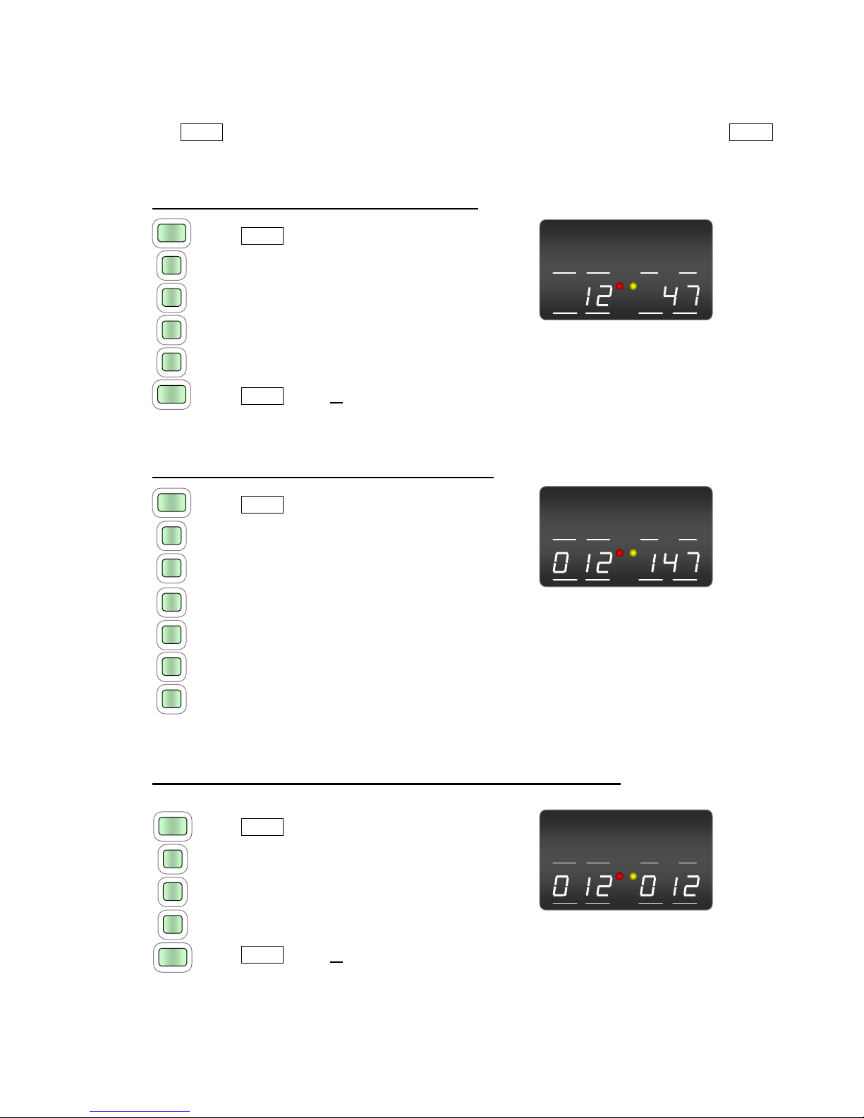
To enter a Wide Band AAR frequency pair press:
1
2
CHAN
CHAN
7
4
T/D HOME
TX RX
TX RX
1. CHAN button
2. Digit 1 of the 2-digit AAR channel for TX
3. Digit 2 of the 2-digit AAR channel for TX
4. Digit 1 of the 2-digit AAR channel for RX Resulting Display
5. Digit 2 of the 2-digit AAR channel for RX
6. CHAN button or wait 2 seconds
To enter a Narrow Band AAR frequency pair press:
T/D HOME
TX RX
TX RX
2
CHAN
7
4
0
1
1
1. CHAN button
2. Digit 1 of the 3-digit AAR channel for TX
3. Digit 2 of the 3-digit AAR channel for TX
4. Digit 3 of the 3-digit AAR channel for TX Resulting Display
5. Digit 1 of the 3-digit AAR channel for RX
6. Digit 2 of the 3-digit AAR channel for RX
7. Digit 3 of the 3-digit AAR channel for RX
For Quick Entry of an AAR frequency pair with the same TX/RX press:
T/D HOME
TX RX
TX RX
1
2
CHAN
CHAN
0
1. CHAN button
2. Digit 1 of the AAR channel
3. Digit 2 of the AAR channel
4. Digit 3 of the AAR channel (if narrowband) Resulting Display
5. CHAN button or wait 2 seconds
OPERATING THE RADIO
-----------------------------------------------------------------------------------------
---------------------------------------------------------------------------------------------------------------
Ritron RCCR Clean Cab User Manual 6
DTMF Tones
DTMF
DTMF tones can be transmitted directly by pressing the
numeric keypad, or the DTMF Button can be used in
conjunction with the numeric keypad to create a DTMF
sequence of up to 3-digits. A DTMF sequence entered
using the DTMF button is stored and displayed, and can
then be transmitted by simply pressing the DISP
dispatch button. DTMF tones are heard on the front-
panel speaker whenever they are being transmitted.
DTMF Disable prevents use of the
DTMF button to create a DTMF
sequence, but does not prevent
sending DTMF directly using the
numeric keypad.
* Disable or # Disable prevents DTMF
characters * or # from being sent
directly whenever the numeric
keypad is pressed.
Keypad Disable prevents DTMF from
being sent directly whenever the
numeric keypad is pressed, but still
allows you to create a DTMF
sequence using the DTMF button.
RCCR Programmer Options
that Affect DTMF Operation
Dispatch Sequence allows a DTMF
Sequence of up to 3-digits
otherwise a single-digit is all that is
allowed.
DTMF Single-Digit
•Sets a single-digit for DISP dispatch button
operation.
•“Dispatch Sequence” selection on the RCCR
programmer must be unchecked.
•The DTMF single-digit will be transmitted when
entered.
•The DTMF single-digit entered will be preceded
by a “D”, appearing in the upper left side of the
display in the area designated “―T/D―”.
•The DTMF single-digit will be retained when the
Channel is changed.
DTMF Sequence
•Allows a DTMF sequence of up to 3-digits for DISP dispatch button operation.
•“Dispatch Sequence” selection on the RCCR programmer must be checked.
•The DTMF dispatch sequence entered will appear in the upper left side of the display in the
area designated “―T/D―”.
•To transmit the DTMF sequence, press the DISP dispatch button.
•The DTMF dispatch sequence will be retained when the Channel is changed.
To enter a Single-Digit DTMF for dispatch press:
T/D HOME
TX RX
TX RX
1. DTMF button
2. Desired DTMF digit.
Radio will transmit the DTMF digit
Resulting Display
DTMF
8

OPERATING THE RADIO
-----------------------------------------------------------------------------------------
---------------------------------------------------------------------------------------------------------------
Ritron RCCR Clean Cab User Manual 7
To enter a DTMF Sequence for dispatch press:
9
0
DTMF
DTMF
8
1. DTMF button
T/D HOME
TX RX
TX RX
2. Digit 1 of the DTMF sequence
3. Digit 2 of the DTMF sequence (if desired)
4. Digit 3 of the DTMF sequence (if desired)
5. DTMF button or wait 2 seconds Resulting Display
(if less than 3 digits are entered)
Single-Tone
TONE
The TONE Button is used in conjunction with the numeric keypad to send one of 9 different AAR
single-tones. Once entered, the tone can be transmitted by simply pressing the DISP dispatch button.
AAR single-tones are heard on the front-panel speaker whenever they are being transmitted.
6 2200
7 2400
8 2600
9 2800
5 1900
4 1800
3 1748
2 1478
AAR Single-Tones
Button Tone (Hz)
1 900
•The AAR single-tone will be transmitted when entered.
•The AAR single-tone entered will be preceded by a “T”,
appearing in the upper left side of the display in the area
designated “―T/D―”.
•Keypad buttons 0, * and # are not valid single-tone entries.
•The AAR single-tone will be retained when the Channel is
changed.
•TONE Disable can be set using the RCCR Programmer to
prevent use of the TONE button to enter or send an AAR single-
tone. This will not prevent the DISP button from transmitting any
AAR single-tone that has been programmed into a HOME
channel.
To enter a Single-Tone press:
T/D HOME
TX RX
TX RX
8
TONE
1. TONE button
2. Desired Single-Tone
Radio will transmit the Single-Tone
Resulting Display

OPERATING THE RADIO
-----------------------------------------------------------------------------------------
---------------------------------------------------------------------------------------------------------------
Ritron RCCR Clean Cab User Manual 8
DTMF or Single-Tone Dispatch
D
I
S
P
The DISP button is pressed to transmit any DTMF or Single-Tone that has been entered into the radio.
•The DTMF sequence or AAR single-tone sent is normally indicated in the upper left side of the
display in the area designated “―T/D―”.
•If no DTMF or Single-Tone is entered the DISP button has no effect.
•HOME channels can be programmed with an associated DTMF or AAR Single-Tone that will
be automatically entered into the “―T/D―” area whenever that HOME channel is selected.
•When a HOME channel is programmed with an alphanumeric description, the DTMF or AAR
Single-Tone will not be displayed until the DISP button is pressed. The DTMF or AAR single-
tone will be shown in the upper left side of the display in the area designated “―T/D―” while
the tone is sent, and will return to the alphanumeric description upon completion of the tone(s).
In the example below HOME channel 002 is programmed with an alphanumeric description
“INDYCOM” and a DTMF sequence “890”.
Alphanumeric Press DTMF or Single-Tone Alphanumeric
Home Channel display ►DISP ►transmitted ►Home Channel display
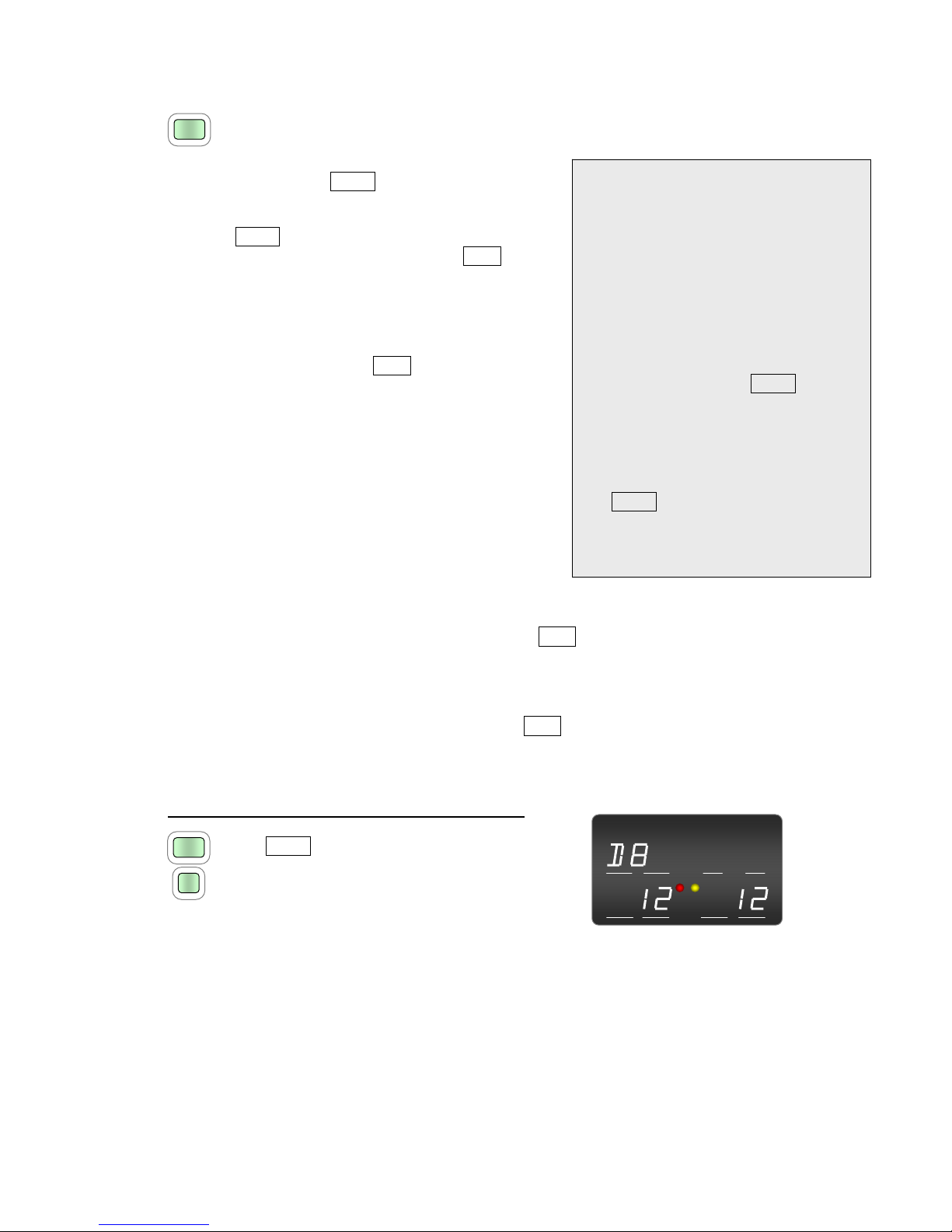
Transmit and Busy Indication
A red “TX” transmit light and yellow “RX” busy light
are located in the center of display. The “TX” lights
any time the radio is transmitting and the “RX” lights
whenever the radio receives a transmission.
T/D HOME
TX RX
RX
T/D HOME
TX RX
TX RX
D
I
S
P
T/D HOME
TX RX
TXT
X
R
X
T/D HOME
TX RX
TX
il
TX RX

OPERATING THE RADIO
-----------------------------------------------------------------------------------------
---------------------------------------------------------------------------------------------------------------
Ritron RCCR Clean Cab User Manual 9
Volume
▼VOL▲
The VOL button is a toggle switch used to incrementally increase
or decrease the front-panel speaker volume. Pressing the right
side of the VOL button will increase speaker volume while
pressing the left side will decrease volume. As the volume is
changed the display will indicate the volume level and a tone will
be heard. Volume can be set to a value between 1 and 20. The
volume level can be adjusted by pressing the VOL button for each
increment, or by holding the VOL button down to automatically
increment.
T/D HOME
TX RX
TX RX
Volume Display
•When pressing the VOL button, any “―T/D―” or “―HOME―” indications on the display will
be momentarily replaced by the Volume Level and will reappear when the VOL button is
released.
•The RCCR PC programmer can be used to set a minimum allowable volume. For example, if
the radio is set for a minimum volume of 3 the VOL button will never be able to lower the
volume below level 3.
•The VOL button does not change the handset speaker audio. Handset volume is at a fixed
level that can be set using the RCCR PC programmer.
•The RCCR PC programmer can set the AUX volume to a fixed level, or allow it to be adjusted
by the VOL button.
PTT (Push-to-Talk)
P
T
T
The PTT button is pressed to transmit voice message from the front-panel microphone. The red “TX”
lamp in the center of the display will illuminate whenever the PTT button is pressed to indicate that the
transmitter is active. The radio will transmit on the channel indicated in the “―TX―”area on the
lower left side of the display.
It is important to monitor the channel before transmitting to avoid interference with other radio users. If
the “―TX―”and “―RX―”are set to the same channel and you hear a received voice signal in the
front-panel speaker, you should wait for the received signal to go away before pressing the PTT
button. The yellow “RX” busy lamp in the center of the display is another indication that a signal is
received.
Brightness Control
Display brightness is automatically adjusted depending on the ambient light in the locomotive cab,
dimming in low light and increasing intensity in high light. The keypad is automatically backlit in low
light conditions.

OPERATING THE RADIO
-----------------------------------------------------------------------------------------
---------------------------------------------------------------------------------------------------------------
Ritron RCCR Clean Cab User Manual 10
Home Channel Selection
HOME
The HOME button is used in conjunction with the numeric keypad to select up to 500 HOME channels.
Each HOME channel can be custom programmed for:
•Transmit frequency and bandwidth
•Receive frequency and bandwidth
•CTCSS or DCS encode and/or decode
•DTMF or Single-Tone dispatch code
•7-character alphanumeric description
A HOME channel is selected by pressing the HOME button and then entering a 1, 2 or 3-digit HOME
channel number using the numeric keypad. Once entered, the transmit and receive channels will be
displayed in the areas designated “―TX―”and “―RX―”. The HOME channel number will be
displayed in the area designated “―HOME―”unless an alphanumeric description has been
assigned, in which case the description will be appear on the top row across the entire width of the
display. If an invalid HOME channel entry is attempted “INVALID” will momentarily show across the
top of the display and no changes will be made.
The following example illustrates a HOME channel number 124 programmed for AAR channel 12
transmit and AAR channel 47 receive with a DTMF dispatch code of 890.
To select a HOME channel press:
1
2
HOME
HOME
4
T/D HOME
TX RX
TX RX
1. HOME button
2. Digit 1 of the HOME channel
3. Digit 2 of the HOME channel (if required)
4. Digit 3 of the HOME channel (if required) Resulting Display
5. HOME button or wait 2 seconds
(if less than 3 digits are entered)
T/D HOME
TX RX
TX RX
If an alphanumeric description “INDYCOM” is
programmed in the example above, the resulting
display would be:
Resulting Display

OPERATING THE RADIO
-----------------------------------------------------------------------------------------
---------------------------------------------------------------------------------------------------------------
Ritron RCCR Clean Cab User Manual 11
Revert to Last TX/RX Channel Pair
A special feature of the HOME button allows the radio to toggle between the last 2 TX-RX channel
pairs entered by pressing the HOME button and then the #button. This can be channel pairs that
were entered via the CHAN button or the HOME button. This is convenient for railroads that operate
on 2 primary TX-RX pairs to allow the user to quickly change between the two.
To toggle between the last two TX-RX channel pairs press:
HOME
1. HOME button
2. # button
#
Error Messages
Error messages are displayed when certain radio malfunctions are detected to alert the user of
potential problems with the unit.
INVALID
This error message will appear momentarily any time an invalid
channel entry is made. If an invalid AAR CHAN button entry or
HOME channel entry is attempted “INVALID” will momentarily show
across the top of the display and no changes will be made.
T/D HOME
TX RX
TX RX
ANTENNA
If an antenna VSWR greater than 3:1 is detected while the radio is
transmitting “ANTENNA” will show across the top of the display. The
display will revert back to normal once the transmitter is released, or if
the high VSWR condition is corrected. The radio will still transmit into
the antenna with VSWR conditions greater than 3:1, albeit at reduced
RF output levels. If the “ANTENNA” error should appear check the
antenna connection to the radio, the antenna cable, and the antenna
itself for damage.
T/D HOME
TX RX
TX RX
RADIO CONNECTORS
-----------------------------------------------------------------------------------------
---------------------------------------------------------------------------------------------------------------
Ritron RCCR Clean Cab User Manual 12
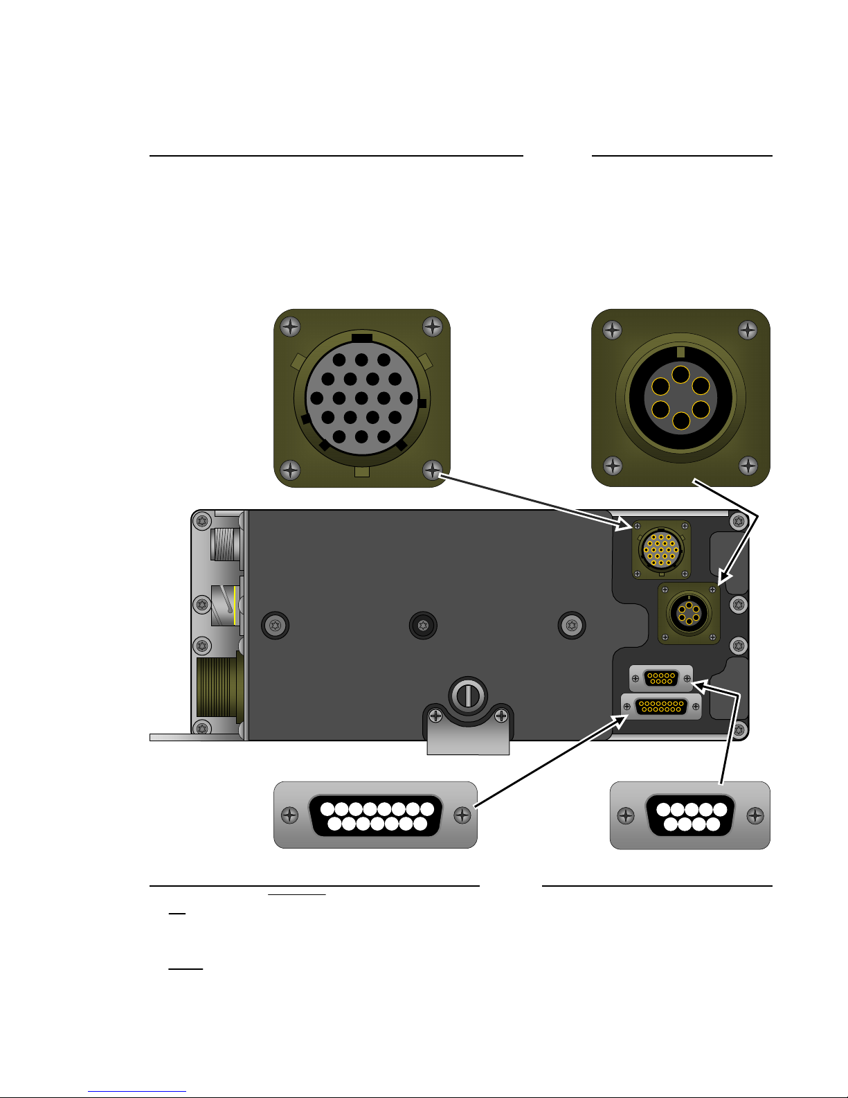
RCCR Connectors – Rear Panel
Remote Control Head (19-Pin Female) Rear Handset (6-Pin)
AMic Audio HNo Connection PNo Connection A Mic Audio
BNo
Connection JVcc RNo Connection B Mic Ground
CNo Connection KNot Used SRXD 232 CPTT
DNo
Connection LGround TTXD 232 DPTT Ground
EMic Ground MSpeaker (-) UHandset Ground E Receive Audio
FNot Used NSpeaker (+) VHandset Audio F Not Used
GNo
Connection
A
B
C
D
E
FG
J
K
L
M
NP
R
ST
U
A
B
C
D
E
F
V
54321
9876
15 14 13 12 11 10 9
8
7654321
Accessory / Program Connector (DB15) Data Connector (DB9)
1TD 6MONITOR 11 GROUND 1No Connection 6DSR
2CD 7SPAREIN 12 RD 2RD 7RTS
3ACC_TX 8SPAREOUT 13 DTR 3TD 8CTS
4EXPTT 9DISC_OUT 14 RTS 4No Connection 9No Connection
5MUTE 10 ACC_AUD 15 CTS 5Ground
F
H
RADIO CONNECTORS
-----------------------------------------------------------------------------------------
---------------------------------------------------------------------------------------------------------------
Ritron RCCR Clean Cab User Manual 13
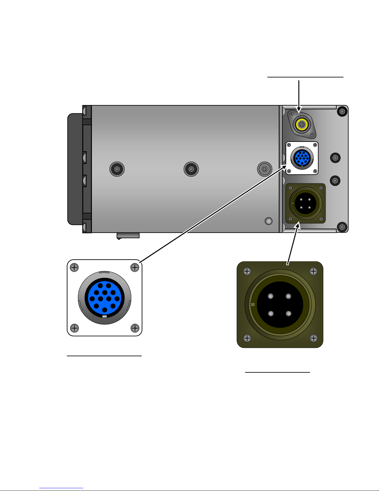
RCCR Connectors – Side Panel
Antenna Connector (SO-239)
Auxiliary Connector (12-Pin)
ARemote
Mic HAudio Ground
BMic Ground J13.6VDC Ground Power Connector (4-Pin)
CRemote
PTT KNot Used A+72 VDC
DPTT Ground LNot Used B-13.6 VDC Ground
ERemote Audio MExternal Speaker (+) C-72 VDC
F+13.6 VDC NExternal Speaker (-) D+13.6 VDC
B
A
C
D E F H
J K L
MN
A B
D C
RADIO CONNECTORS
-----------------------------------------------------------------------------------------
---------------------------------------------------------------------------------------------------------------
Ritron RCCR Clean Cab User Manual 14
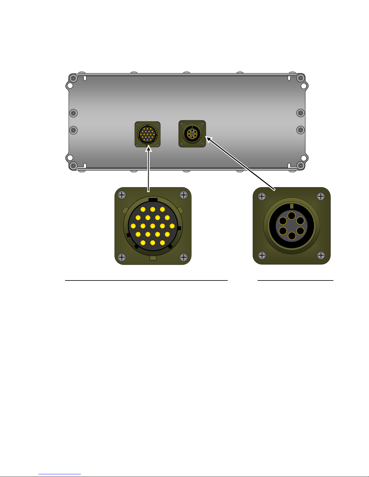
RCCR Connectors – Remote Head
A
M
L
K
J
H G
E
D
C
B
PN
U
TS
R
A
B
C
D
E
F
V
F
Remote Control Head (19-Pin Male) Remote Head Handset (6-Pin)
AMic Audio HNo Connection PNo Connection A Mic Audio
BNo Connection JVcc RNo Connection B Mic Ground
CNo
Connection KNot Used SRXD 232 CPTT
DNo Connection LGround TTXD 232 DPTT Ground
EMic Ground MSpeaker (-) UHandset Ground E Receive Audio
FNot Used NSpeaker (+) VHandset Audio F Not Used
GNo
Connection
PROGRAMMING THE RADIO
-----------------------------------------------------------------------------------------
---------------------------------------------------------------------------------------------------------------
Ritron RCCR Clean Cab User Manual 15
f
Getting Started
The RCCR radio is programmed through the DB-15 connector located on the rear of the radio. Ritron
model RCCR-PAC programming cable connects the radio to the serial communications port of the
computer. The RCCR programmer is a Windows based software package used to set all radio
operating parameters.
Connecting to the Computer
The RCCR radio is connected to the serial communications port o
your computer using the PC/Radio cable assembly included in the
RITRON model RCCR-PCPK-1.0 Programmer Kit. If you do not
have the PC/Radio cable assembly it can be purchased from
RITRON. The DB-15 to DB-9 cable is RITRON PN# RCCR-PAC.
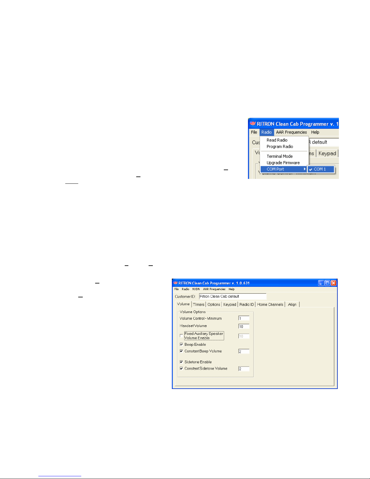
Once the PC/Radio cable assembly has been connected to the
computer, the correct COM Port must be selected from the COM
Port menu item under the Radio menu on the RCCR P
Main
rogrammer
screen.
The Programmer Screen
The programmer screen pictured below will appear whenever the RITRON RCCR Programmer is first
opened. This is the starting point of any programming operation you wish to perform.
If an RCCR radio is connected to the computer when the programmer is first opened the radio’s
programming will be automatically read in and displayed. If a radio is not connected the Radio
Definition File named RCCR_default.rdf will be read in. See “Open File” and “Save File” topics in this
manual for information on the use of Radio Definition Files.
The pull-down menus File and Radio at the top left of the screen are used to open and save Radio
Definition Files for recurring use, and to read and write data to the RCCR radio.
Menu item Help will open a
programmer help file, while menu
item AAR Frequencies will open a
file containing a full list of AAR
channels. Both files are in pdf format
and require that Adobe Acrobat
Reader be installed on your computer
hard drive to view them. They cannot
be edited and are for reference only.
RCCR Programmer Screen
The Customer ID field allows you to
enter up to 25 characters of text to help
identify the radio or Radio Definition FIle.
A row of tabs, located below the pull-
down menus, are used to access the
many programmable attributes of the
RCCR radio.

PROGRAMMING THE RADIO
-----------------------------------------------------------------------------------------
---------------------------------------------------------------------------------------------------------------
Ritron RCCR Clean Cab User Manual 16
Programmer Menus
Open File
Radio Definition Files saved to your computer hard drive can be read to review programming of radios
currently in service or for programming other radios to the same set-up.
To read a Radio Definition File:
1. From the File menu, select the Open File menu item.
2. The Open dialog box will appear. The standard Windows directory tree is available for navigation
to alternative file locations on your computer hard drive. Use the “Look In:” pull-down menu to
select the location of the Radio Definition File to be read. The dialog box will initially open to the
Windows directory that contains the RCCR Programmer software.
3. Radio Definition Files are saved with an “.rdf” file extension. The dialog box will present a list of all
“.rdf” files contained in the currently displayed Windows file directory.
4. Select the filename of the Radio Definition File to be opened from the list.
5. Press
the Open button to open the Radio Definition File. As an alternative, you can double-click
on a filename in the list to open the Radio Definition File.
6. The programmer screens will now
display the radio programming
information read from the Radio
Definition File.
Open Dialog Box
Save File
After a radio’s programming has been read or changed, you may want to save a Radio Definition File
detailing the radio programming for future reference. Radio Definition Files are useful for reviewing a
radio’s programming while the radio is in service or to save a radio set-up for programming into other
radios.
To save a Radio Definition File:
1. From the File menu, select the Save File menu item.
2. The Save dialog box will appear. The standard Windows directory tree is available for navigation
to alternative file locations on your computer hard drive. Use the “Look In:” pull-down menu to
select the location where the Radio Definition File is to be saved. The dialog box will initially open
to the Windows directory that contains the RCCR Programmer software.

PROGRAMMING THE RADIO
-----------------------------------------------------------------------------------------
---------------------------------------------------------------------------------------------------------------
Ritron RCCR Clean Cab User Manual 17
3. Radio Definition Files will be saved with an “.rdf” file extension. The dialog box will present a list of
all “.rdf” program files contained in the currently displayed Windows file directory. When creating a
filename make sure it is unique and not contained in the list of existing files because the
programmer will simply overwrite the existing file if the filename is the same.
4. Enter a unique filename into the “File name” box. You must enter the “.rdf” extension after the
filename or the programmer will not be able to read the file at a later time.
NOTE: The Radio Definition File named RCCR_default.rdf is read into the programmer
automatically when the programmer is first started. This file must be located in the same Windows
directory that contains the RCCR Programmer software. Edit and save this file to create your own
unique radio personality that is displayed every time the RCCR Programmer software is started.
5. Press
the Save button to save the Radio Definition File to your computer hard drive.
Print Radio Data
You can print out a pre-formatted report of the radio
programming or a Radio Definition File.
Print Dialog Box
To print a radio programming report:
1. Read the radio or open a Radio Definition File.
2. From
the File menu, select the Print Radio
Data menu item.
3. The
Print dialog box will appear to allow setting
of printer options. The default printer as defined
in the Windows printer set-up of your computer
will be automatically selected.
4. The report will always detail the radio’s
programming as it appears on the screen. To
be sure the report reflects the actual radio
programming, be sure to Read Radio or
Program Radio just before printing the report.
Print Custom Frequency Data
You can print out a pre-formatted list of all Custom frequencies contained in the radio programming or
in a Radio Definition File. A list of all AAR standard frequencies can be printed by selecting the AAR
Frequencies menu selection to open and print the associated pdf file.
To print a radio frequency list:
1. Read the radio or open a Radio Definition File.
2. From
the File menu, select the Print Frequency Data menu item.
3. The
Print dialog box will appear. The default printer as defined in the Windows printer set-up of
your computer will be automatically selected.
4. The report will always detail the radio’s programming as it appears on the Custom Frequencies
list. To be sure the report reflects the actual radio programming, be sure to Read Radio or
Program Radio just before printing the report.
PROGRAMMING THE RADIO
-----------------------------------------------------------------------------------------
---------------------------------------------------------------------------------------------------------------
Ritron RCCR Clean Cab User Manual 18
Print Home Channel Data
You can print out a pre-formatted list of all Home Channels contained in the radio programming or in a
Radio Definition File. This list will detail the custom programming of all Home Channels available on
the radio.
To print a list of all Home Channel programming:
1. Read the radio or open a Radio Definition File.
2. From
the File menu, select the Print Home Channel Data menu item.
3. The
Print dialog box will appear. The default printer as defined in the Windows printer set-up of
your computer will be automatically selected.
4. The report will always detail the radio’s programming as it appears on the Home Channels list. To
be sure the report reflects the actual radio’s programming, be sure to Read Radio or Program
Radio just before printing the report.
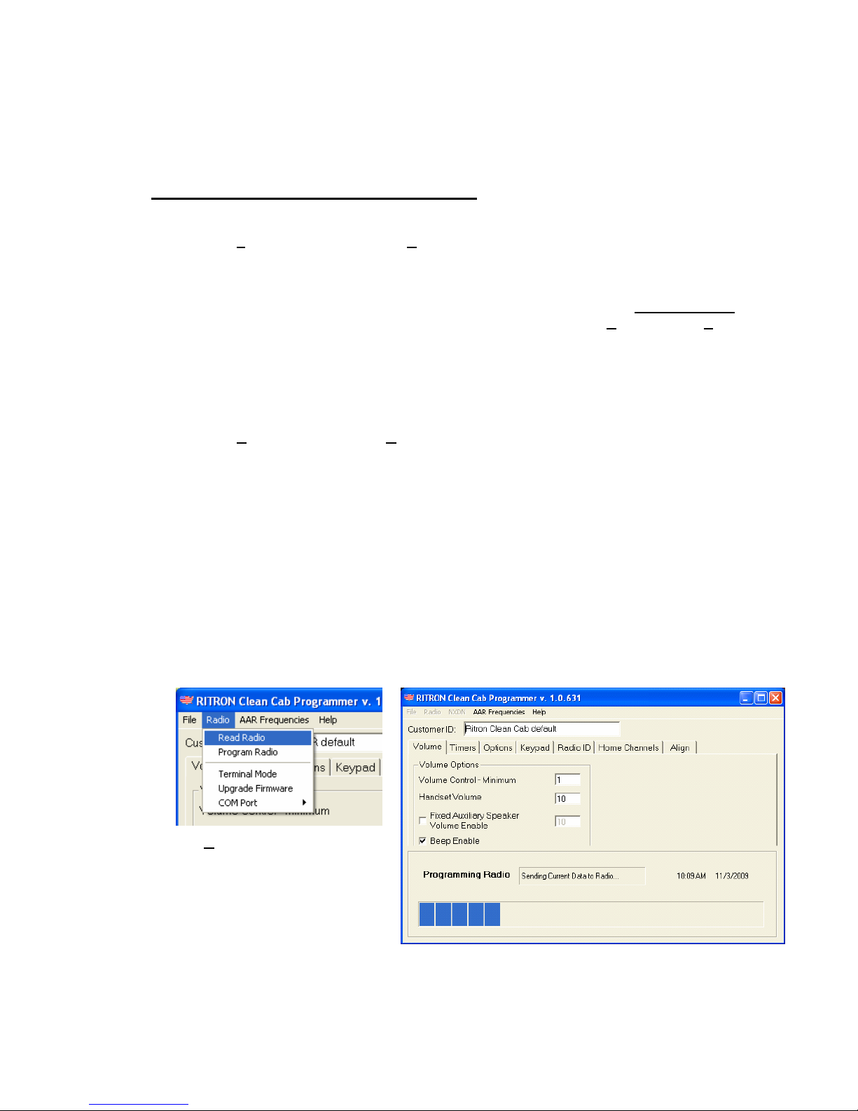
Read Radio
1. With the PC/Radio cable assembly connected to the computer and the radio, turn the radio on.
2. From the Radio menu, select the Read Radio menu item.
3. The programmer will “ping” the radio to establish
communications. If the programmer does not see a radio the
No Radio! message box will appear. Be sure the cable is
connected, the correct COM Port is selected and the radio is o
The
n.
4. programmer will read the radio and fill all screens with the
5. ” to indicate it has re-started to normal operating mode after the radio’s
6. mation on the various screens.
radio’s programmed information. A communications status box
will appear at the bottom of the screen while the programmer is
reading the radio.
The radio will “beep
“No Radio!” Message Box
programming has been read.
Review the programming infor
Radio Pull-down Menu
Communications Status Box
Table of contents
Other Ritron Radio manuals

Ritron
Ritron RPM 60 Series User manual

Ritron
Ritron Jobcom JBC-100 User manual

Ritron
Ritron QUICK TQLK Instructions for use

Ritron
Ritron RBS-477DMR User manual

Ritron
Ritron SLX Series User manual

Ritron
Ritron RF320 Series User manual

Ritron
Ritron DATAFLOW RTU User manual

Ritron
Ritron MOBILE RADIO User manual

Ritron
Ritron RPM 60 Series User manual

Ritron
Ritron RPM-150 User manual


