Ritron SLX Series User manual
Professional Radio
User Guide
P/N 14500054 Rev A 07/05
SLX Series
SLX Series

Radio 1700mAh Li-Ion
Battery Pack
De ktop
Rapid Charger
Antenna
Hand Strap U er Manual
ITEMS

Content ............................................................. 1
Radio Overview .................................................. 2
Hot Key ............................................................. 3
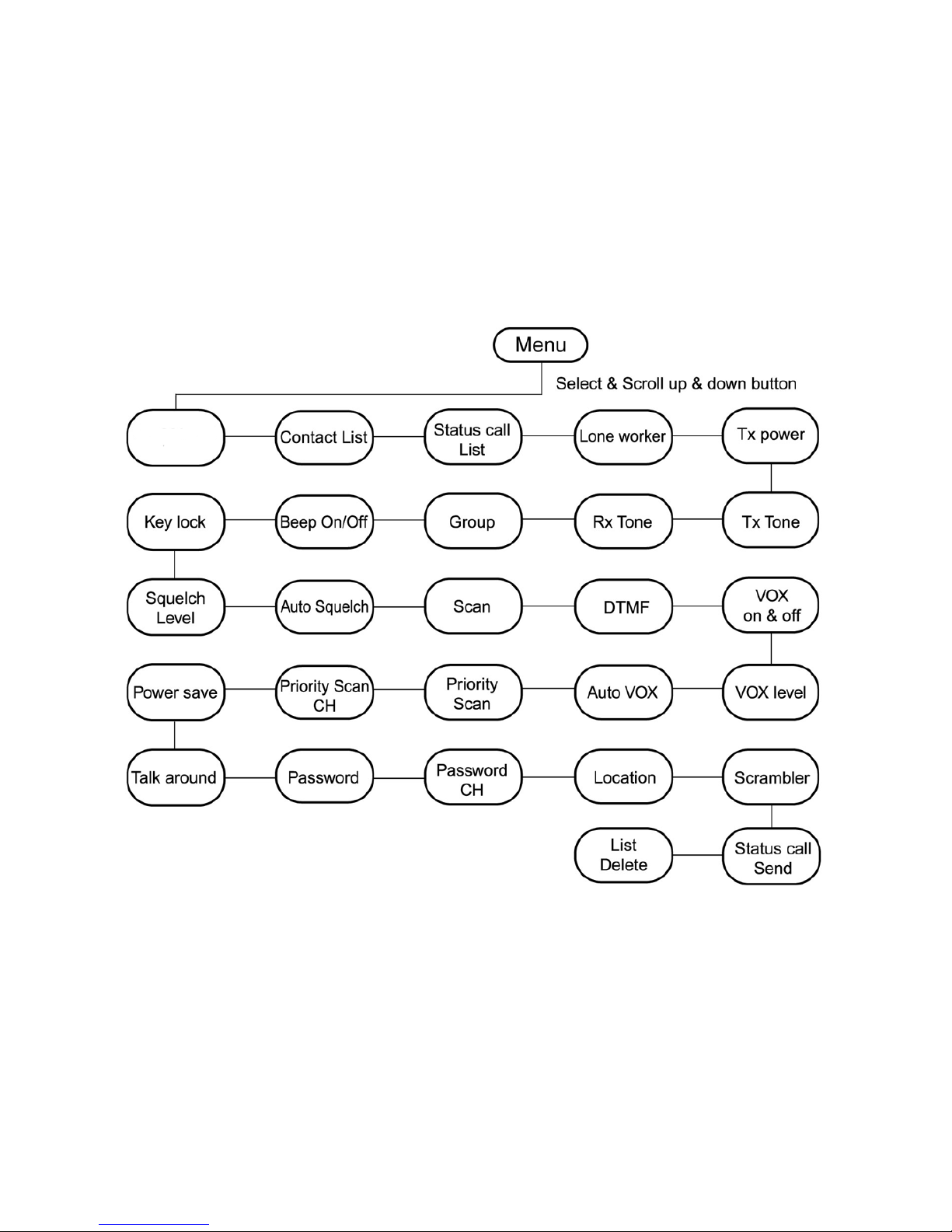
Menu Navigation Chart ....................................... 4
LCD Di play Icon .............................................. 5
Attaching the Battery .......................................... 6
Removing the Battery ......................................... 6
Attaching the Antenna ........................................ 7
Removing the Antenna ....................................... 7
Turning the Radio On-Off ................................... 8
Adju ting the Radio Volume ............................. 8
Selecting a Radio Channel ................................. 9
TX/RX Frequency Code ................................... 10
Tx Tone .............................................................. 11
Rx Tone .............................................................. 11
Key lock .............................................................. 12
Scramble ............................................................ 12
Squelch .............................................................. 13
Ear PTT .............................................................. 13
Approval ............................................................. 14
CONTENTS
1

RADIO OVER
VIEW
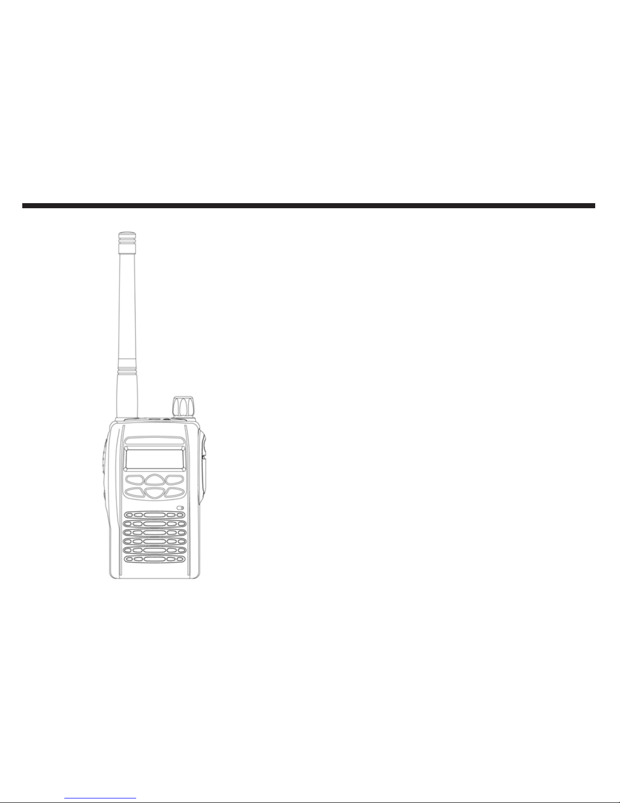
Thank you for purcha ing the RITRON SLX-Serie
tran ceiver . Read all in truction carefully and
completely before u ing tran ceiver. Thi in truction
manual contain important operating in truction for
the tran ceiver .
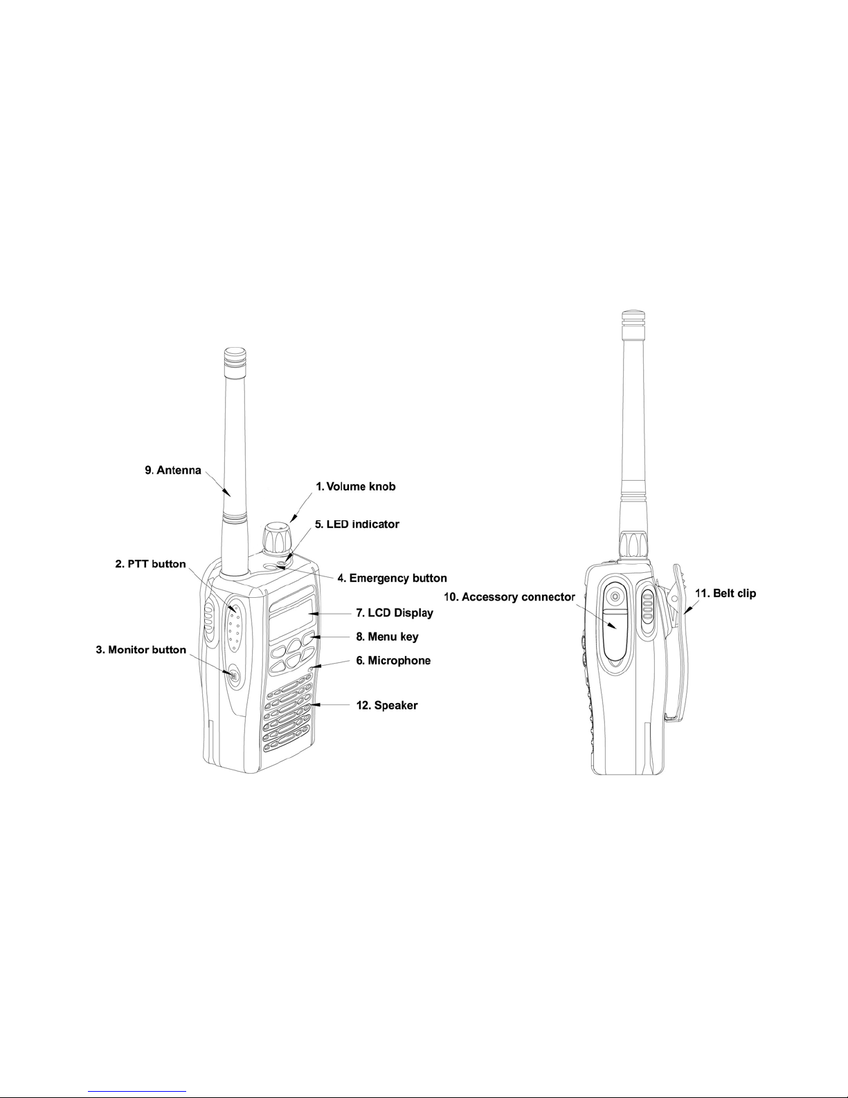
OPERATION AND CONTROL FUNCTIONS
Radio Controls
The number below refer to the illu tration on the
in ide front cover.
1. On-Off / Volume Knob
Turn the power/volume control knob clockwi e
to turn the radio on.
2. Push to Talk Button (PTT)
Pu h and hold to tran mit; relea e to receive
ignal.
3. Monito Button
Pre the Monitor key momentarily to di able
the Tone quelch.
4. Eme gency Button
The emergency function allow you to end an
emergency ignal quickly and ea ily to your
Ba e Station, etc. in ca e of emergency.
5. LED Indicato
6. Mic ophone
7. LCD Display
8. Menu Keys
9. Antenna
10. Accesso y Connecto
Connect head et , remote peaker/
microphone and other acce orie . Replace
attached du t cap when not in u e.
11. Belt Clip
Programmable Buttons
All of your radio button can be programmed (By
Programming Software) to activate the radio
feature .
2

ot Keys
The front panel button (Hot Key ) can be programmed for variou feature . The following diagram
how how the Hot Key are programmed from the factory.
Orange button: Emergency When pressed for 2 seconds, the programmed Emergency
Code is automatically transmitted.
Monitor Button: Monitor adio programmed with sub-tone: When pressed 1 time, will
disable sub-tone. When pressed 2 times, will disable sub-
tone and carrier squelch.
P1 Button: TX Power Level When pressed will toggle between High Power (4W UHF/
5W VHF) and Low Power (1W).
P2 Button: Contact List When pressed, preprogrammed names from the Contact
List appear in the display. By pressing the PTT button, a
programmed code associated with the Contact List name will
be automatically transmitted.
P3 Button: Scan When pressed, the radio will scan those channels with the
scan function enabled.
Arrow Up Button: Channel/Scroll Up When pressed, the radio channel or feature list selected will
be incremented to the next one.
Arrow Down Button: Channel/Scroll Down When pressed, the radio channel or feature list selected will
be incremented to the next one.
Check Button: Menu Ena le When pressed, will display list of features that have been
enabled on the Menu List.
3
TX/ X
Freq
4
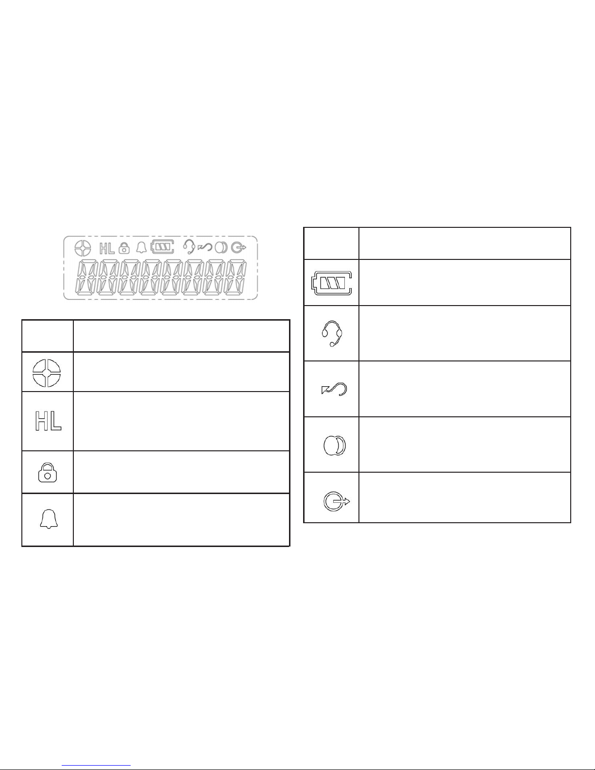
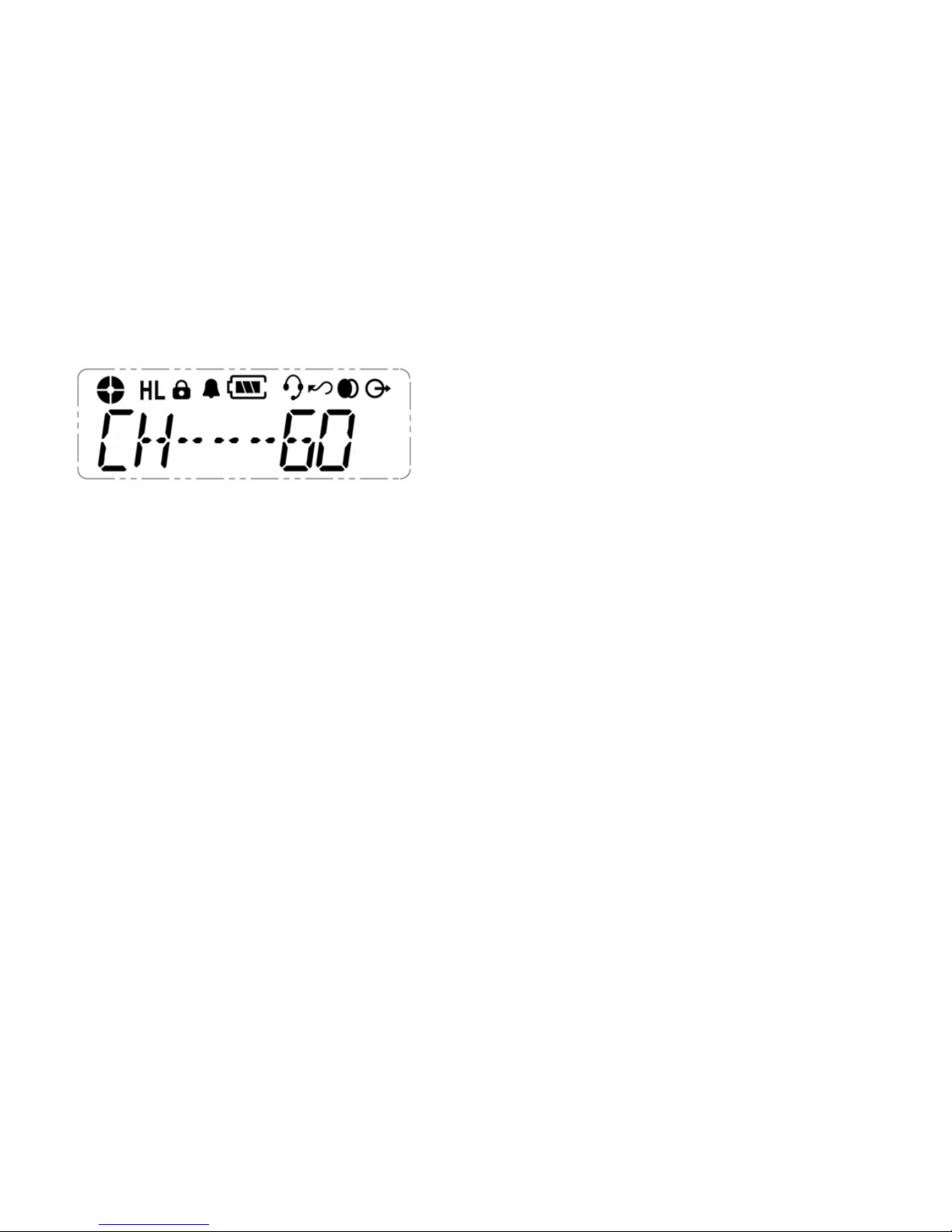
Indicate relative ignal trength level.
Power Level Indicator
H i for high power. L i for low
power.
Key Lock Indicator
Appear during key lock function ON.
Alert (Beep) ON/OFF Indicator
Appear when beep ound i turned
ON.
LCD Display and Icons
Battery Level Indicator
Indicate remaining battery power.
VOX Indicator
Appear when VOX function i
turned ON.
Scan Indicator
Appear when Scan function i
activated.
Scrambler Indicator
Appear while the voice crambler
function i activated.
Talk Around Indicator
Symbol Name and Description
Symbol Name and Description
5
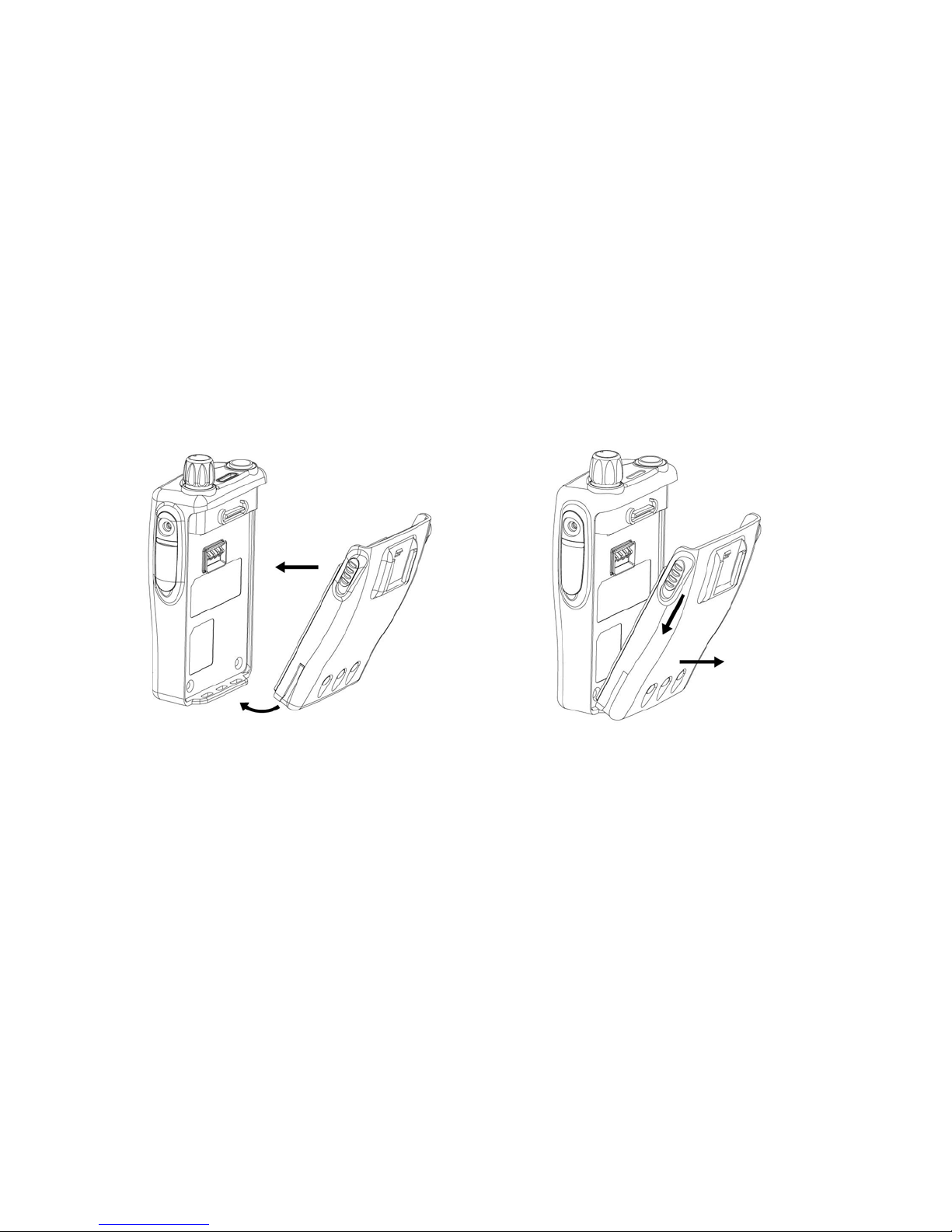
1. Fit the exten ion at the bottom of the battery
into the lot at the bottom of the radio body.
2. Pre the top part of the battery toward the
radio until you hear a click.
ACCESSORY INFORMATION
Attaching the Battery
1. Turn off the radio, if it i turned on.
2. Slide the battery latche , on both ide of the
battery, downward .
3. Pull the top part of the battery away from the
radio body, and remove the battery.
Removing the battery
6
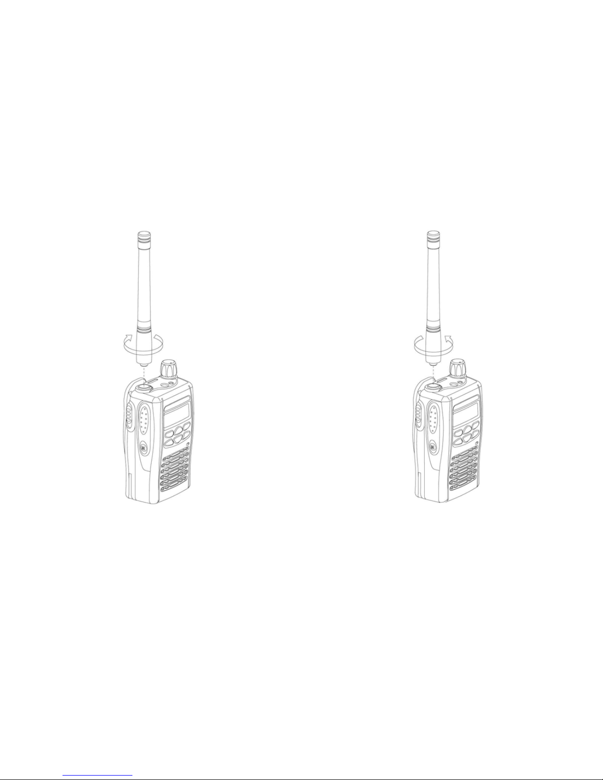
1. Align the threaded end of the antenna with the
radio antenna connector.
2. Turn the antenna clockwi e to fa ten it.
Attaching the Antenna Removing the Antenna
1. Turn the antenna counterclockwi e until you
can remove it.
7

Adjusting the Radios Volume
Turn the On-Off/Volume Control knob to adju t the
ound level.
RADIO OPERA ION
urning the Radio On or Off
To turn the radio on, turn the On-Off/Volume Control
knob clockwi e.
To turn the radio off, turn the On-Off/Volume Control
knob counterclockwi e until you hear a click.
8
Select the de ired channel by u ing the Up/Down
Key. Each pre increa e /decrea e the channel
number. When held down, the channel increa e
continuou ly.
Select the de ire channel by u ing the Down Key.
Each pre decrea e the channel number. When
held down, the channel decrea e continou ly.
ransmission Signal
To tran mit, monitor the channel, and make ure it i
clear. THIS IS AN FCC REQUIREMENT!
To tran mit, pre and hold the PTT witch. Speak
into the microphone area of the panel grill in a normal
voice level. To return to the Receive mode, relea e
the PTT witch.
Selecting a Radio Channel
Thi radio offer up to 60 channel .
User Program Mode
In order to make change to the feature of the
radio via the menu li t, the radio mu t fir t be
placed in U er Program Mode.
To put the radio into U er Program Mode:
1. Make ure On/Off Volume control i in the Off
po ition.
2. Pre the Menu button while rotating the On/
Off Volume control to the On po ition.
3. A hort beep will be heard and the character
CH-01 will be hown in the di play.
4. U e the Up/Down arrow to elect the channel
to be changed.
5. Once the channel i elected, pre the menu
button and the character FREQ will be
hown in the di play.
6. U e the Up/Down arrow to elect the feature
to be changed.
7. After all change have been made and aved,
rotate the ON/Off volume control to the Off
po ition and then back to the On po ition for
normal radio operation.
9

X/RX Frequency
To change the tran mit and receive frequency of a
certain channel:
1. After radio i placed into U er Program Mode
and the de ired channel to be changed i
elected, u e the Up/Down arrow to elect the
menu feature FREQ.
2. Pre the menu button and the character 00
will be di played in the di play.
3. U e the Up/Down arrow to elect the 2-digit
code corre ponding to the de ired Rx/Tx
frequency a hown in Table 1 Programmable
Frequency Code .
4. When the de ired code i di played, pre the
menu button to ave the election.
5. To return to normal operation, turn radio Off
and then back On.
Table 1. Programmable Frequency Codes
VHF MURS
Code No. MHz Color ot Bandwidth(kHz)
01 154.6000 Green Dot 25
02 154.5700 Blue Dot 25
19 151.8200 MURS 12.5
20 151.8800 MURS 12.5
21 151.9400 MURS 12.5
22 154.6000 MURS/Green 12.5
23 154.5700 MURS/Blue 12.5
00 DELETE ode
VHF Business Band
Code No. MHz Color ot Bandwidth(kHz)
03 151.6250 Red Dot 25
04 151.9550 Purple Dot 25
05 151.9250 25
06 154.5400 25
07 154.5150 25
08 154.6550 25
09 151.6850 25
10 151.7150 25
11 151.7750 25
12 151.8050 25
13 151.8350 25
14 151.8950 25
15 154.4900 25
16 151.6550 25
17 151.7450 25
18 151.8650 25
24 151.7000 12.5
25 151.7600 12.5
26 152.7000 25
00 DELETE ode
Per FCC rules and regulations, a given radio must not be
programmed to contain a mix of both VHF Business Band and
VHFMURS frequencies.
10

x one
Thi function i u ed to change Tx Tone uch a
CTCSS, DCS.
Rx one
Thi function i u ed to change Rx Tone uch a
CTCSS, DCS.
Method:
1. to enter Menu Mode.
2. to croll li t until Tx Tone.
3. to elect.
4. or to elect CTCSS or DCS.
5. to elect.
There are 38 CTCSS code (1~38)
There are 83 DCS code (101~183)
0 mean no Tone.
Method:
1. to enter Menu Mode.
2. to croll li t until Tx Tone.
3. to elect.
4. or to elect CTCSS or DCS.
5. to elect.
There are 38 CTCSS code (1~38)
There are 83 DCS code (101~183)
0 mean no Tone.
11

Key Lock
Key Lock Indicator
Appear when key lock function i ON.
Scrambler
Thi function provide higher communication
ecurity.
Method:
1. to enter Menu Mode.
2. to croll li t until Key Lock.
3. to elect.
4. or to elect lock or unlock.
5. to elect.
Method:
1. to enter Menu Mode.
2. to croll li t until Scrambler.
3. to elect.
4. or to elect on or off.
5. to elect.
12

Squelch Level
Thi function et the point at which the radio
receiver will open depending upon the ignal
trength of the tran mitted ignal.
Ear P
Thi function allow for the radio internal
microphone to be enabled when an audio
acce ory i plugged in.
Method:
1. to enter Menu Mode.
2. to croll li t until EAR PTT.
3. to elect.
4. or to elect ON or OFF.
5. to ave and return to normal operation.
Method:
1. to enter Menu Mode.
2. to croll li t until Squelch.
3. to elect.
4. or to et level; the larger the number,
the more ignal i needed to open the receiver.
5. to ave and return to normal operation.
13

APPROVAL
FCC F exposure limits. A proper antenna is the antenna
supplied with this radio by the manufacturer for use with
this radio.
Do not transmit for more than 50% of total radio use time
(50% duty cycle). Transmitting more than 50% of the
time can cause FCC F exposure compliance
requirements to be exceeded.
Always use the supplied accessories (antenna, batteries,
belt clips, speaker/mic, etc.)
Use of unauthorized accessories can cause the FCC F
exposure compliance requirements to be exceeded.
Always keep the antenna at least 2.5 cm (1 inch) away
from the body when transmitting and only use the belt-
clips, when attaching the radio to your belt, etc., to ensure
FCC F exposure compliance requirements are not being
exceeded.
2. CE APPROVAL
This transceiver meets the following essential
requirement.
EN 300 086-1/2
1. FCC APPROVAL
FCC ID: SLX-100 AIE IT21-150
SLX-400 AIE IT21-450
Safety T aining Info mation
Your IT ON FM Handheld Transceiver generates F
electromagnetic energy during transmit mode.
This radio is designed for and classified as Controlled
Exposure/Occupation Environment, meaning it must be
used only during the course of employment by individuals
aware of the hazards, and the ways to minimize such
hazards.
This radio is not for use by the General Population/
Uncontrolled Environment.
This radio complies with FCC F radiation exposure limits
set forth for a controlled environment.
This radio should be installed and operated with a
minimum distance of 2.5 centimeters between the radio
and yoru body. Therefore, to ensure that your exposure
to F electromagnetic energy is within the FCC allowable
limits for occupational use, always follow below
information.
Do not operate the radio without a proper antenna as this
may damage the radio and may also cause you to exceed
0678 !
14

505 We t Carmel Drive Carmel, IN 46032 USA
P. O. Box 1998 Carmel, IN 46082-1998 USA
Ph: 317-846-1201 Fax: 317-846-4978 Email: [email protected] Web ite: www.ritron.com
Other manuals for SLX Series
3
Table of contents
Other Ritron Radio manuals

Ritron
Ritron RPM-150 User manual

Ritron
Ritron MOBILE RADIO User manual

Ritron
Ritron RCCR User manual

Ritron
Ritron DATAFLOW RTU User manual

Ritron
Ritron SLX Series User manual

Ritron
Ritron RBS-477DMR User manual

Ritron
Ritron RPM 60 Series User manual

Ritron
Ritron QUICK TQLK Instructions for use

Ritron
Ritron RPM 60 Series User manual

Ritron
Ritron RF320 Series User manual


