Rittal CMC III Temperature/Humidity Sensor 9
5 Installation
EN
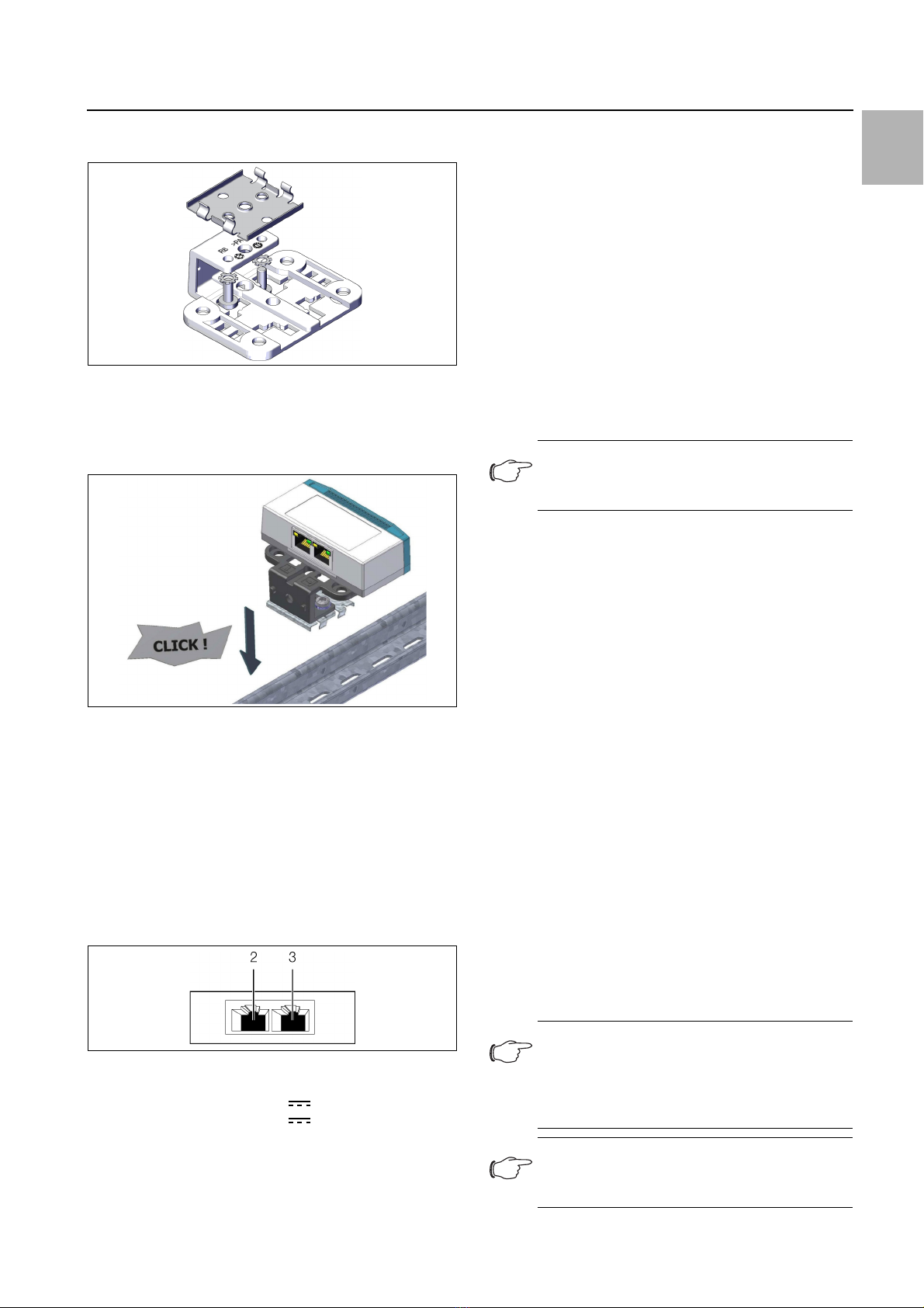
First screw the bracket onto the spring clip provided
for installation on a top-hat rail.
Fig. 5: Fastening the bracket to the spring clip
Then place the temperature/humidity sensor on the
bracket (fig. 2) and latch it in place (fig. 3).
Latch the spring clip into place at the desired position
on the top-hat rail.
Fig. 6: Fastening the spring clip to the top-hat rail
5.4 Connecting the sensor
The CAN bus connection supplies the temperature/hu-
midity sensor with the necessary operating voltage. A
separate power supply unit does not need to be con-
nected.
Use a CAN bus connection cable to connect the tem-
perature/humidity sensor to a CAN bus interface on
the CMC III Processing Unit or the neighbouring com-
ponent on the CAN bus (fig. 7, item 2).
Fig. 7: Rear of the temperature/humidity sensor
Key
2 CAN bus connection, 24 V
3 CAN bus connection, 24 V
The following CAN bus connection cables from the
CMC III accessories can be used:
– DK 7030.090 (length 0.5 m)
– DK 7030.091 (length 1 m)
– DK 7030.092 (length 1.5 m)
– DK 7030.093 (length 2 m)
– DK 7030.480 (length 3 m)
– DK 7030.490 (length 4 m)
– DK 7030.094 (length 5 m)
– DK 7030.095 (length 10 m)
The software is updated, if necessary, after being con-
nected. The status LED of the temperature/humidity
sensor glows blue throughout the entire update process
and also flashes purple while the sensor itself receives
an update.
In addition, the status LED of the CMC III Processing
Unit flashes white and a corresponding message ap-
pears on the website.
The update of the sensor is complete when the following
conditions have been fulfilled:
1. The LEDs on the CAN bus connection of the sensor
light green.
2. The multi-LED of the sensor behind the front panel
flashes blue and green, yellow or red, depending on
the condition of the sensor.
Further components are connected as a daisy chain.
If necessary, connect another component (e.g. anoth-
er sensor type) to the second, free CAN bus interface
of the temperature/humidity sensor (fig. 7, item 3).
Status change display:
– The two green and the two red CAN bus LEDs on
the CAN bus connection flash.
– The multi-LED of the Processing Unit flashes contin-
ually in the sequence green – orange – red.
– The multi-LED of the temperature/humidity sensor
flashes blue continuously.
Press the "C" key on the CMC III Processing Unit (an
initial audio signal will sound) and keep it pressed for
approx. 3 seconds until a second audio signal is
heard.
Note:
No settings can be modified as long as the
update process is running.
Note:
The multi-LED of the temperature/humidity
sensor lights red continuously for approx.
5 seconds while the average value of the
temperature is being determined.
Note:
See section 6.3.1 "Multi-LED displays" for a
list of all of the multi-LED displays.