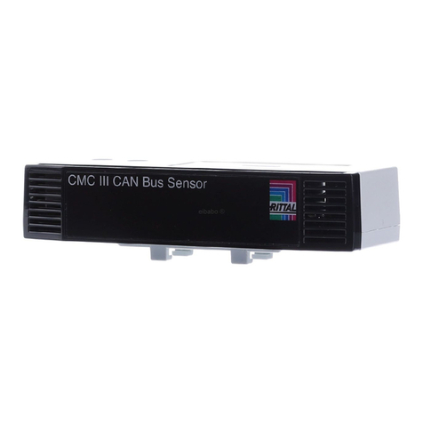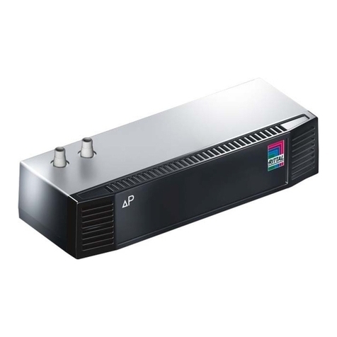
Rittal CMC III Temperature/Humidity Sensor 7
EN
4 Assembly
4.1 Assembly instructions
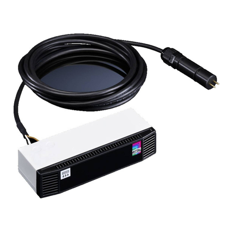
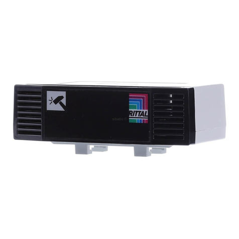
The assembly of the temperature/humidity sensor is made as shown in fig. 2.
5 Installation and operation
5.1 Operating and display elements
The operating and display elements are shown in fig. 3.
Key for fig. 3
1 Multi-LED for the status display
2 CAN bus connection, 24 V
3 CAN bus connection, 24 V
5.2 Installation
Connect the temperature/humidity sensor with a CAN bus connection cable to the CMC III PU or to
the neighbouring elements on the CAN bus (fig. 3, item 2, 3).
Display of the status change:
– The two green and the two red CAN bus LEDs on the CAN bus connection flash.
– The multi-LED of the Processing Unit flashes continually in the green – orange – red sequence.
– The multi-LED of the temperature/humidity sensor flashes blue continuously.
Press the "C" key on the CMC III PU (a first audio signal is issued) and keep it pressed for approx.
3 seconds until a second audio signal is issued.
Display of the status change on the CAN bus LEDs:
– Green LEDs light continuously: CAN bus status "OK".
– Red LEDs light continuously: CAN bus status faulty.
Display of the status change on the multi-LED of the Processing Unit.
– Continuous green light: All units attached to the CAN bus have the "OK" status.
– Continuous orange light: At least one unit attached to the CAN bus has the "warning" status.
– Continuous red light: At least one unit attached to the CAN bus has the "alarm" status.
Display of the status change on the multi-LED of the temperature/humidity sensor.
– The multi-LED lights red continuously for approx. 5 seconds while the average value of the meas-
ured values is being determined.
– Continuous blue flashing: Communication over the CAN bus.
– Green flashing: When the measured value changes or, at the latest, every 5 seconds.
– Continuous orange flashing: The temperature/humidity sensor has the "warning" status. Fast
flashing: Upper limit value exceeded. Slow flashing: Lower limit value exceeded.
Note:
For exact temperature and humidity measurement sufficient air circulation inside the en-
closure or server rack is required. The position of the temperature/humidity sensor must
ensure sufficient air through-flow and vent slots must not be obstructed.
If this is not possible, the temperature sensor DK 7030.110 in combination with the ex-
ternal sensor cable must be used in place of the internal temperature sensor for exact
temperature measurement. However, this combination is not suitable for exact humidity
measurement.
Assembly, Installation and operation
