Rittal 3105.310 User manual

Montage-, Installations- und Bedienungsanleitung
Assembly and operating instructions
Manuel d’installation et de maintenance
Montage- en bedieningshandleiding
Montage- och hanteringsanvisning
Istruzioni di montaggio e funzionamento
Instrucciones de montaje
Schaltschrank-Heizgerät SK
Panel heater SK
Resistance chauffante SK
Schakelkastverwarmingen SK
Värmeelement
för apparatskåp SK
Riscaldatore anticondensa SK
Resistencia calefactora SK
SK 3105.xxx


5
Notes
Enclosure heaters with fans
Model No. SK 110 V 3105.410 3105.420 3105.430
Model No. SK 230 V 3105.380 3105.390 3105.400
Dimensions mm
W
H
D
103
200
103
103
200
103
103
200
103
Hole distance mm 171
Rated operating voltage V, Hz 110 or 230 V, 50/60
Continuous thermal output
at T
u
= 10 ûC250 W
1)
400 W
1)
800 W
1)
Pre-fuse gG for 110 V 4 A 6 A 10 A
Pre-fuse gG for 230 V 4 A 6 A 6 A
1)
Output with fan.
We reserve the right to make technical modifications.
A
Enclosure heaters without fans
Model No. SK 3105.310 3105.320 3105.330 3105.340 3105.350 3105.360 3105.370
Dimensions mm
W
H
D
45
120
46
45
120
46
64
155
56
64
155
56
64
230
56
90
165
75
90
180
75
Hole distance mm 42 60
Rated operating
voltage Volt, Hz
110 – 240 V, 50/60
Continuous thermal
output at T
u
= 10 ûC
8 – 10 W 18 – 20 W 23 – 30 W 49 – 50 W 63 – 75 W 86 – 100 W
130 – 150 W
Pre-fuse T 2 A 4 A
Special voltages available on request. We reserve the right to make technical modifications.
A
1. Technical speciÞcations
2. Mounting
The panel heater is fitted vertically, i.e. with
the connection terminal or fan facing down-
wards. To permit the required convection, a
minimum clearance to the adjacent compo-
nents must be observed. A safety clearance
of at least 300 mm must be left above the
heater in the case of heaters with fans, and
100 mm for heaters without fans. (For both
a thermal safety clearance to the sides of
60 mm and 100 mm at the bottom is
required).
If these clearances are observed, the ambi-
ent temperature does not rise above 65 ˚C.
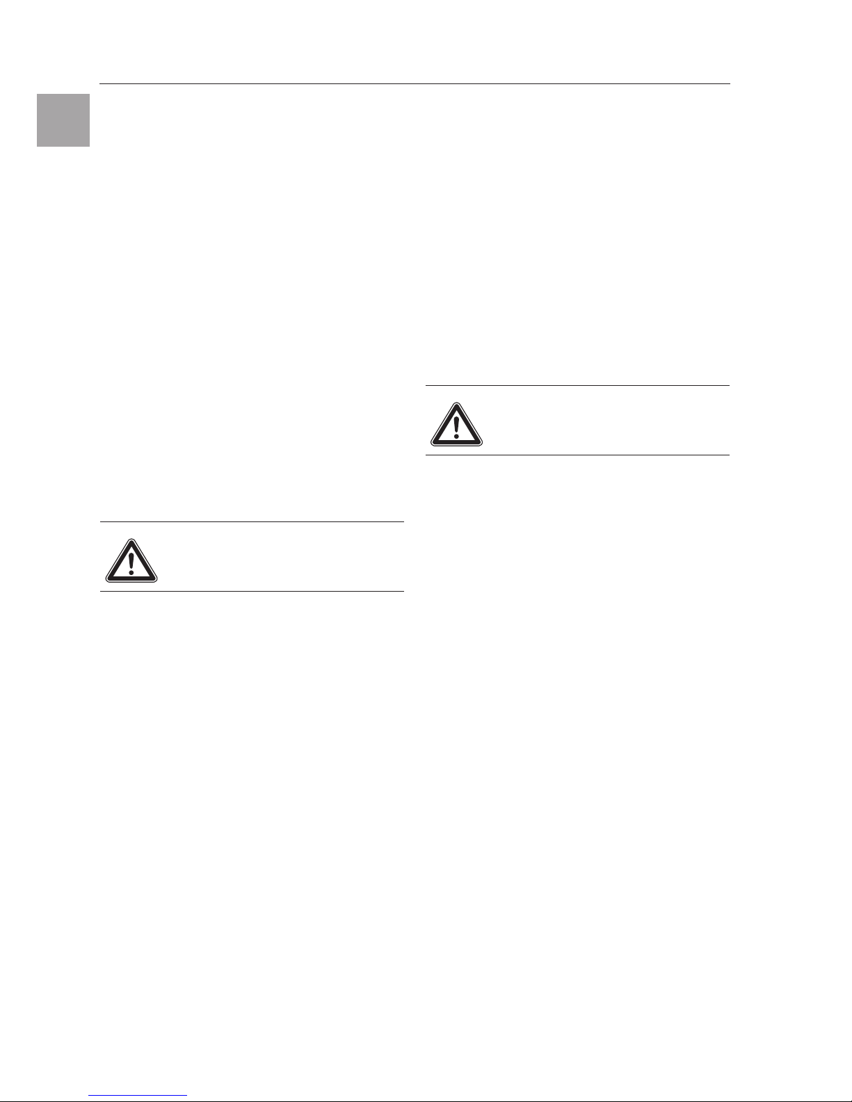
2.1 Snap-type fastening onto a 35 mm
support rail DIN EN 50 022 (Fig. 1.1).
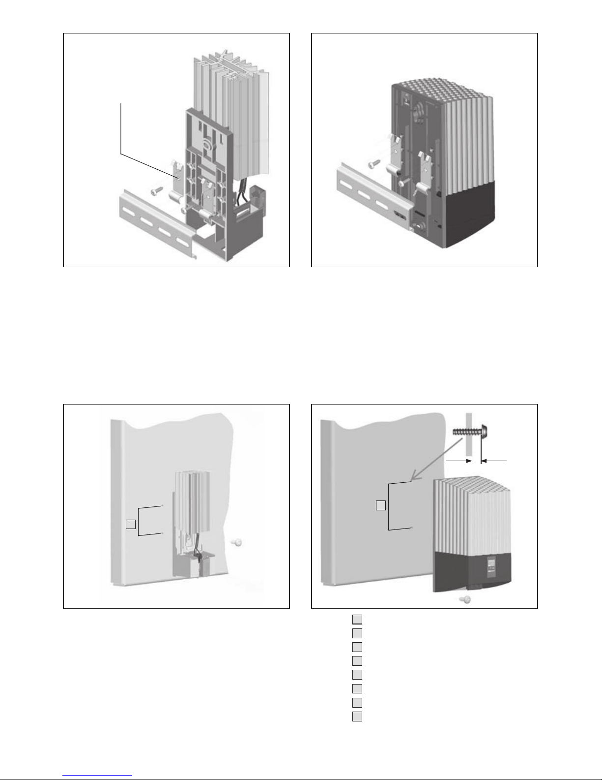
2.2 Screw fastening onto the mounting plate
(Fig. 1.2).
It should be ensured that the heater and con-
nection cables are mounted firmly and secu-
rely. Electric cables must not touch the body
of the heater fan and must not be routed
directly past the hot air outlet.
The heater must not be mounted in the vici-
nity of flammable materials.
Rittal enclosure heater assembly instructions
EN
6
3. Mains connection
The heater must be connected to a power
supply of the voltage stated on the rating
plate via the quick-connect terminals. The
unit must be connected to the mains via an
isolating device which ensures at least 3 mm
contact opening when switched off.
Electrical connections must be made using
solid wire (max. 2.5 mm
2
) or stranded wire
with wire end ferrules.
Due to the specific characteristics of the PTC
heater element, the momentary switch-on cur-
rent may be up to 6 A. A slow-blowing fuse
(gL) is therefore imperative. IEC 6100-4-5
requires that the customer provides safety
devices for impulse voltages of more than
1000 V. The double connection terminal per-
mits the cascading of several heaters and
thus simplifies wiring. A separate thermostat
(SK 3110.000) or a digital thermostat
(SK 3114.200) must be used to control the
enclosure temperature.
The humidity of the air in the enclosure can
be controlled by incorporating a hygrostat
(SK 3118.000).
3.1 Proper usage
Rittal enclosure heaters were developed and
designed in accordance with the state of the
art and the recognised rules governing tech-
nical safety. Nevertheless, if used improperly,
they may pose a threat to life and limb or
cause damage to property. The heater is only
designed to heat components and to be
installed inside housings and enclosures.
The manufacturer will not be liable for any
damages caused as a result of improper use,
or for incorrect assembly, installation or use.
All risk is borne solely by the user.
4. Safety notes
●
When carrying out the electrical installation,
it is important to observe all valid national
and regional regulations as well as the
provisions of the responsible power supply
company.
●
Electrical installation must only be carried
out by a qualified electrician who is
responsible for compliance with the existing
standards and regulations.
●
Use only original spare parts!
●
The heater must not be touched while
switched on : Risk of burns from hot
surfaces! The heater must be allowed to
cool for approx. 15 minutes after switching
off.
5. Scope of supply
1 heater
1 set of assembly instructions
Assembly parts
6. Warranty
This unit is covered by a 1-year guarantee
from the date of supply, subject to correct
usage. Within this period, the returned unit
will be repaired in the factory or replaced free
of charge.
Unauthorised utilisation or incorrect connec-
tion will invalidate the manufacturer’s guaran-
tee. No liability will be assumed for any
damage arising from such situations.
Caution!
Overvoltage peaks of more than
2 kV may destroy the unit.
Caution!
Risk of burns from
hot surfaces!
Notes
Rittal enclosure heater assembly instructions
EN
19
Ab
b. 1.1: Schnappbefestigung auf 35 mm-Tragschiene DIN EN 50 022
Fig
. 1.1: Snap-type fastening onto a 35 mm support rail DIN EN 50 022
Fi
g. 1.1 : Fixation par enclenchement sur un rail porteur de 35 mm selon DIN EN 50 022
Afb.
1.1: Snapbevestiging op een 35 mm-montagerail DIN EN 50 022
Bild
1.1: Ihakningsmontage på en 35 mm profilskena DIN EN 50 022
Fig.
1.1: Fissaggio ad innesto su guida DIN 35 mm secondo EN 50 022
Imagen 1.1: Fijación a presión sobre un carril soporte de 35 mm DIN EN 50 022
図
1.1:
DIN レール(
35 mm DIN EN 50 022)へのスナップ固定
Ab
b. 1.2: Schraubbefestigung auf Montageplatte
Fig
. 1.2: Screw fastening onto a mounting plate
Fi
g. 1.2 : Fixation par vis sur une plaque de montage
Afb.
1.2: Schroefbevestiging op een montageplaat
Bild
1.2: Skruvmontage på en montageplåt
Fig.
1.2: Fissaggio a vite su piastra di montaggio
Imagen 1.2: Fijación atornillada sobre una placa de montaje
図
1.2:
マウンティングプレートへのねじ取付け
SK 3105.310 – SK 3105.370
1 x SK 3105.310 – 3105.350
2 x SK 3105.360 – 3105.370
SK 3105.380 – SK 3105.430
A
A
max. 6 mm
= Lochabstand
= Hole distance
= Distance entre les perçages
= Hartafstand
= Hålavstånd
= Interasse fori
= Distancia entre centros de taladros
= 取付穴間の距離A
A
A
A
A
A
A
A
This manual suits for next models
12


