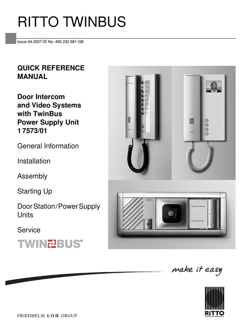
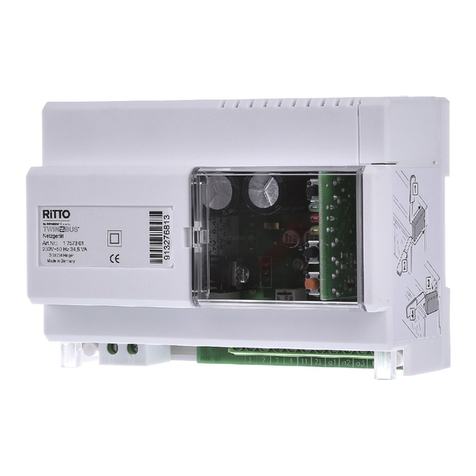
RiTTO 1 7817 Operating and installation instructions

DAusgabe 1.2005/ld.-Nr. 400 231 792
1
RITTO TWINBUS Video-Hausstationfür
Objekte S/W 1 7817
Beschreibung • Installation • Montage • Inbetriebnahme
Gerätebeschreibung
Die Video-Hausstation 1 7817 ist für den Sprech- und Sichtver-
kehr zur Türstation und zum Öffnen der Haupttür und/oder
Etagentür vorgesehen. Abhängig von der Anlage kann über die
Video-Hausstation z.B. das Treppenhauslicht geschaltet wer-
den.
Die Video-Hausstation 1 7817 wird zusammen mit schwarz/
weiß Kameras wie z.B. 1 7653, 1 4780, 1 4786 und 1 4880
verwendet.
Lieferumfang
Die Video-Hausstation wird mit Anschlussklemmen für
TwinBus und Videobus geliefert.
Ausstattung
Technische Daten
Zubehör
Montagevoraussetzungen
Hinweis:
Bitte beachten Sie vor der Installation und Inbetrieb-
nahme die allgemeinen Hinweise in der aktuellen
Ausgabe des TwinBus Systemhandbuches.
Ausstattung Bemerkung
Bildschirm 4“ S/W
Türöffnertaste hinterleuchtet
Lichtschaltfunktion über Schaltgerät 1 4981
Optische Türrufanzeige
Rufabschaltung (Stumm-
schaltung)
Türruf wird optisch
signalisiert
Lautstärkeregelung 4-stufig
Mithör-/Mitsehsperre
Nachtdesign Türöffnertaste
hinterleuchtet
Ruftonunterscheidung
Ruftöne 5 für die Hauptklingel
einstellbar
00639-0
Videoeinschaltdauer fest, 90 s
Einlernbare Klingeltasten 10
Maße (H x B x T) in mm 220 x 250 x 50
Betriebsspannung min. 14 V AC / 16 V DC
Leistungsaufnahme 5 W eingeschaltet
Umgebungstemperatur 0 bis 40 °C
Max. relative Luftfeuchte 60%
Zubehör Art.-Nr. Funktion
Tischkonsole 1 7312 Konsole für die Verwen-
dung als Tischgerät
UP-Rahmen 1 7325 Rahmen und Dose für
Unterputz- und Hohl-
wandmontage
Montageart benötigtes Zubehör
Aufputz
Unterputz UP-Rahmen 1 7325
Tischgerät Tischkonsole 1 7312 und
eine handelsübliche IAE/
UAE-Anschlussdose.
Anschluss 8 adrig
Hinweis:
Die Video-Hausstation 1 7817 verfügt über kein
Rufanschaltrelais und keine Taste für Sonder-
funktionen. Ein Bildspeicher kann auch nicht nach-
gerüstet werden. In diesen Fällen ist die Video-
Hausstation 1 7816 einzusetzen.
Ausstattung Bemerkung

2
D
Installation
Video-Türsprechanlage mit dezentraler Speisung
Blockschaltbild: Video-Türsprechanlage für das
Mehrfamilienhaus.
* Bitte beachten Sie die rote Markierung
Schaltplan:Video-Türsprechanlage für das Mehrfamilien-
haus.
1 6477
2
1 6477
2
1 6477
28
2x2
2x2
2x2
1 7573
2
1 6477
1 7817
1 7817
1 7817
UV
2
ED
2
ED
2
ED
B0096-0
RiTTO
1 4780
1 4753
1 4760
S0103-2
11
NL
432
21
1
34 a121 b a2 a3
NL 2 31
1 4760
1 4780
1 4753
2VaVb1
1 6477
NL123
abVbVa
ED
ED
1 6477
ED
NL123
abVa Vb
ED
ED
1 6477
ED
NL123
abVa
Vb
Va Vb
ED
ED
1 6477
ED
a1
1 7573
1 7817
1 7817
1 7817
Va Vb
Va Vb
Hinweis:
Ein Parallelbetrieb von Video-Hausstationen S/W
1 7817 auf einer Klingeltaste ist nicht möglich.

3
D
Installation
Video-Türsprechanlage mit zentraler Speisung
Blockschaltbild: Video-Türsprechanlage für das Mehr-
familienhaus mit 3 Hauptbuslinien.
Schaltplan: Video-Türsprechanlage für das Mehrfamili-
enhaus mit 3 Hauptbuslinien mit zentraler
Speisung und Linienverteiler 1 4813.
* Bitte beachten Sie die rote Markierung
** Bitte beachten Sie die Verbindung des Systembus
*** Max. 12 Video-Hausstationen
B0095-2
a3
2x2+2
2x2+2
2x2+2
a2
2x2+22x2+22x2+2
2x2+22x2+22x2+2
2x2+22x2+2
a1 max. 12max. 12max. 12
2
ED
2
ED
2
ED
2
ED
2
ED
2
ED 1 78171 7817 1 7817
1 78171 7817 1 7817
1 4780
1 4753
1 4753
1 4760
RiTTO
8
2
1 75731 4874 1 4874 1 4813
1 6477 1 4874
UV
Hinweis:
Ein Parallelbetrieb von Video-Hausstationen S/W
1 7817 auf einer Klingeltaste ist nicht möglich.
S0104-2
Va Vb Va Vb Va Vb
1 7817
abVa Vb
ED
ED
11 21 a1 b a2NL
432
2
1
134
VbVa VbVa VbVaE++VbVa
NL 2 31
1 4760
1 4780
a3
1 7573
ED
a1
1 7817
abVa Vb
ED
ED
ED
1 7817
abVbVa
ED
ED
ED
1 7817
abVa Vb
ED
ED
ED
a2
1 7817
abVa Vb
ED
ED
ED
1 7817
abVbVa
ED
ED
ED
1 7817
NL
abVa Vb
ED
ED
ED
a3
1 7817
1 4874
a
+
bVa Vb
ED
ED
ED
1 7817
abVbVa
ED
ED
ED
1 2VbVa
1 4813
1 6477
NL
1 4874
+
NL
1 4874
+
1 4753
max. 12 max. 12 max. 12
Va Vb
Va Vb
Va Vb
Va Vb
Va Vb
Va Vb

4
D
Montage
➤Entnehmen Sie das TwinBus Gerät und die mitgelieferten
Bauteile der Verpackung.
➤Stellen Sie bitte die Bedienungsanleitung des TwinBus
Gerätes Ihrem Kunden zur Verfügung. Die Bedienungs-
anleitung befindet sich abgedruckt auf der Verpackung
oder liegt dem Gerät bei.
Aufputzmontage
➤Bitte entnehmen Sie die Klemme der Verpackung.
* Transportsicherung bei der Video-Hausstation entfernen.
1
2
3
2
2
2
100640-0
200 mm
11 mm
ab
VaVa
Vb
ED ED
Vb
~~
00641-0
2
1*
00642-0
Achtung!
Beschädigung des Geräts durch Kabel-
bruch.
Beim Schließen des Gerätes darf das
Anschlusskabel nicht zwischen Gehäusebo-
den und Bildröhre verklemmt werden.
ab
VaVa
Vb
EDED
Vb
~~
3
4 x
2 x 5
42
1
4 x
00643-0
ab
VaVa
Vb
EDED
Vb
~~
00644-0
3
2
1
2
00670-0

5
D
Unterputz-/Hohlwandmontage
➤Einen UP-Rahmen 1 7325 eingipsen oder mit den bei-
liegenden Hohlwandkrallen befestigen.
1. Hohlwandkrallen
2. Befestigungsschrauben für Hohlwandkrallen
3. Einputzschutz
h: 242 mm
b: 282 mm
t: 65 mm
* Transportsicherung bei der Video-Hausstation entfernen.
Hinweise:
Der Einputzschutz (3) in dem UP-Kasten dient
als Schutz für Verschmutzung. Er sollte erst vor
der Montage der Video-Hausstation entfernt
werden.
Bei unverputzten Wänden ist bei der Montage
die noch aufzubringende Putzstärke zu beach-
ten.
t
h
b
2
3
1
00193-0
11 mm
ab
Va VaVb
ED ED
Vb
~~
200 mm
00645-0
2
1*
00642-0
ab
VaVa
Vb
EDED
Vb
~~
3
4 x
5
2 x 4
2
1
00646-0
ab
VaVa
Vb
EDED
Vb
~~
00647-0

6
D
Montage als Tischgerät
Für die Montage benötigen Sie eine Tischkonsole 1 7312 und
eine IAE/UAE8-Anschlussdose.
* Transportsicherung bei der Video-Hausstation entfernen.
➤IAE/UAE-Anschlussdose gemäß Tabelle anschließen und
montieren.
4
2
2
1
2
3
00648-0
2
1*
00642-0
2
1
2
4
3
2 x
6
2 x
5
00649-0
Achtung!
Beschädigung des Geräts und der ange-
schlossenen Kameras.
Auf die Klemmen Va und Vb darf keine
Spannung aufgelegt werden.
Hinweis:
Bei Tischmontage die beiliegende Schraubklemme
verwenden.
Adernfarbe
Anschlussleitung
1 7312
Klemmen in der
Video-Haussta-
tion
IAE/UAE8
weiß a 1
braun b 2
grün ED (Va)3
gelb ED (Vb)4
grau Va 5
rot Vb 6
blau ~ 7
schwarz ~ 8
Achtung!
Beschädigung des Geräts.
Der Westernstecker des Handapparates darf
nicht in Buchsen anderer Hersteller oder
Systeme eingesteckt werden.
Hinweis:
Ein Durchschleifen des Videosignals Va, Vb ist unter
Verwendung eines Tastenadapters 1 4645 für die
Etagendrückerfunktion möglich.
ab
Va Va
Vb
ED ED
Vb
~~
ab
VaVa
Vb
EDED
Vb
~~
1
2
00650-0

7
D
Anschluss
Schaltplan:Anschluss mit dezentraler Stromversorgung.
Schaltplan:Anschluss mit zentraler Stromversorgung.
Bis zu 12 Video-Hausstationen werden aus dem
Netzgerät Video 1 4874 gespeist.
Inbetriebnahme
Die Inbetriebnahme kann über die Video-Hausstation oder
über den Etagendrücker vorgenommen werden. Die Inbetrieb-
nahme über den Etagendrücker ist sehr nützlich, wenn Sie kei-
nen Zugang zu der Wohneinheit haben.
Damit der Bediener den Rufton der Hauptklingel ändern kann,
ist die Hauptklingel bei einer Neueinstellung als erste Klingel-
taste einzulernen. Für weitere Klingeltasten ist der Vorgang zu
wiederholen.
Bei der Inbetriebnahme mit zwei Personen können Sie die
Sprechanlage benutzen.
Die Videoverbindung zwischen Video-Hausstation und der
Türstation wird automatisch durch die Bedienung der Klingelta-
ste an der Türstation aufgebaut.
Die Video-Hausstation kann dezentral von einem ihr zugeord-
neten Netztrafo 1 6477 gespeist werden. Es können aber auch
bis zu 12 Video-Hausstationen durch das Netzgerät Video
1 4874 gespeist werden.
Bedienelemente
1 Potentiometer, Pegel Videobild
2 Rote LED
Einstellschutz
Über das TwinBus Netzgerät können die angeschlossenen
Sprechstellen mit einem Einstellschutz gegen unbeabsichtigte
Veränderungen gesichert werden – siehe Systemhandbuch
Einen aktivierten Einstellschutz erkennen Sie am negativen
Quittungston beim Betätigen der Einstelltaste.
Inbetriebnahme über die Video-Hausstation
Ein-Mann-Inbetriebnahme
Zwei-Mann-Inbetriebnahme
Hinweis:
Leuchtet die rote LED, liegt Spannung auf den
Anschlüssen Va und Vb zur nächsten Video-
Hausstation. Die Video-Hausstation schaltet aus
Sicherheitsgründen nicht ein.
5
3
1
2
2
4
00651-0
S0101-2
1 7817
NL123
abVbVa
ED
ED
1 6477
ED
Va Vb
abED
ED
ED
1 7817
Va Vb
NL +
1 4874
Va Vb
S00102-2
Tätigkeit Ergebnis
Tätigkeit Ergebnis
1
2
00665-0
RiTTO
< 1 min
RiTTO
RiTTO
2
’2’
’ok’ ’ok’
’2’
RiTTO
< 1 min
’2’
RiTTO

D
RITTO GmbH & Co. KG
Rodenbacher Straße 15
D-35708 Haiger/Germany
Phone +49(0)2773/812-0
Fax +49(0)2773/812-999
1/05 Stand bei Drucklegung. Technische Änderungen vorbehalten. Copyright © 2005 by RITTO GmbH & Co. KG
Wurde die Zeitfrist überschritten:
➤Wiederholen Sie den Vorgang.
Ist der Einlernvorgang fehlgeschlagen:
➤Prüfen Sie am TwinBus Netzgerät, ob der Einstellschutz
aktiviert ist – siehe Systemhandbuch.
Inbetriebnahme mit dem Etagendrücker
Wurde die Zeitfrist überschritten:
➤Wiederholen Sie den Vorgang.
Ist der Einlernvorgang fehlgeschlagen:
➤Prüfen Sie am TwinBus Netzgerät, ob der Einstellschutz
aktiviert ist – siehe Systemhandbuch.
Einstellungen
Videoeinschaltdauer
Das Videobild wird 90 Sekunden angezeigt.
Einstellungen löschen
Mit dieser Funktion werden die eingelernten Klingeltaster ge-
löscht. Bitte notieren Sie sich ggf. vor dem Löschen die vorhan-
denen Kundeneinstellungen.
Wurden die Einstellungen nicht gelöscht:
➤Prüfen Sie am TwinBus Netzgerät, ob der Einstellschutz
aktiviert ist – siehe Systemhandbuch.
➤Wiederholen Sie den Vorgang.
✔kurzer Ton: Das Gerät ist betriebsbereit.
/kein Ton: Zeitfrist überschritten.
/langer Ton: Einlernvorgang ist fehlgeschlagen.
Tätigkeit Ergebnis
✔kurzer Ton: Das Gerät ist betriebsbereit.
/kein Ton: Zeitfrist überschritten.
/langer Ton: Einlernvorgang ist fehlgeschlagen.
Gefahr!
Lebensgefahr durch Hochspannung.
Die Platine der Bildröhre nicht berühren.
Hinweis:
Einbaulage der Bedienelemente – siehe Seite 7.
"P"
> 5 s
< 3 min
> 5 s
RiTTO
< 1 min
’2’
RiTTO
Tätigkeit Ergebnis
Videobildpegel
Tätigkeit Ergebnis
✔kurzer Ton: Einstellungen wurden gelöscht.
/langer Ton: Einstellungen wurden nicht gelöscht.
~
1
1
> 5 s

GB Version 1.2005/Running number 400 231 792
3
RITTO TWINBUS Video Indoor Station for
Objects B/W 1 7817
Description • Installation • Assembly • Start-up
Device description
The Video Indoor Station 1 7817 is designed to be used for the
speech and visual communication to the door station and for
opening the main door and/or the floor door. Depending on the
unit, the indoor video station can, for example, be used to
switch the staircase well lighting on and off.
The Video Indoor Station 1 7817 is used together with black
and white cameras, e.g., 1 7653, 1 4780, 1 4786 and 1 4880.
Scope of delivery
The video indoor station is supplied with connection terminals
for TwinBus and Videobus.
Features
Technical data
Accessories
Conditions for installation
Note:
Please read the general notes in the current edition
of the TwinBus system manual before starting the
installation and the start-up.
Features Comments
Monitor 4” B/W
Door opener button illuminated
Light switching function using the 1 4981
switching device
Visual door ringing
indicator
Ring muting function Door ringing is visually
signalled
Volume control 4-setting
Privacy button
Night design Door opener button
illuminated
Call differentiation
00639-0
Call tones 5 adjustable for main bell
button
Video switch-on duration fixed, 90 seconds
Programmable ringing
buttons
10
Dimensions (H x W x D) in mm 220 x 250 x 50
Operating voltage min. 14 V AC / 16 V DC
Power consumption 5 W when switched on
Ambient temperature 0 to 40 °C
Max. relative humidity 60%
Accessories Part
no.
Function
Desktop module 1 7312 Console for use as a
desktop module
Flush-mounted frames 1 7325 Frames and sockets for
concealed and cavity wall
installation
Type of assembly Accessories required
Surface mounted
Flush-mounted 1 7325 flush-mounting
frame
Desktop module 1 7312 desktop console
and a commercially
available IAE/UAE box.
8-wire connection
Note:
The 1 7817 video indoor station does not have any
muting relay nor any key for special functions. An
image memory also cannot be added as upgrade.
The 1 7816 video indoor station should be used in
such situations.
Features Comments

4
GB
Installation
Video door intercom with decentral power supply
Block diagram: Video door intercom for the multi-family
residence.
* Please observe the red marking
Circuit diagram:Video door intercom for the multi-family
residence.
1 6477
2
1 6477
2
1 6477
28
2x2
2x2
2x2
1 7573
2
1 6477
1 7817
1 7817
1 7817
UV
2
ED
2
ED
2
ED
B0096-0
RiTTO
1 4780
1 4753
1 4760
S0103-2
11
NL
432
21
1
34 a121 b a2 a3
NL 2 31
1 4760
1 4780
1 4753
2VaVb1
1 6477
NL123
abVbVa
ED
ED
1 6477
ED
NL123
abVa Vb
ED
ED
1 6477
ED
NL123
abVa
Vb
Va Vb
ED
ED
1 6477
ED
a1
1 7573
1 7817
1 7817
1 7817
Va Vb
Va Vb
Note:
The Video Indoor Stations B/W 1 7817 cannot be
operated in parallel on a single push-button.

5
GB
Installation
Video door intercom with central power supply
Block diagram: Video door intercom for a multifamily
residence with 3 main bus lines.
Circuit diagram: Video door intercom for a multi-family
residence with 3 main bus lines with central
power supply and 1 4813 line distributor.
* Please observe the red marking
** Please observe the system bus connection
*** Max. 12 video indoor stations
B0095-2
a3
2x2+2
2x2+2
2x2+2
a2
2x2+22x2+22x2+2
2x2+22x2+22x2+2
2x2+22x2+2
a1 max. 12max. 12max. 12
2
ED
2
ED
2
ED
2
ED
2
ED
2
ED 1 78171 7817 1 7817
1 78171 7817 1 7817
1 4780
1 4753
1 4753
1 4760
RiTTO
8
2
1 75731 4874 1 4874 1 4813
1 6477 1 4874
UV
Note:
The Video Indoor Stations B/W 1 7817 cannot be
operated in parallel on a single push-button.
S0104-2
Va Vb Va Vb Va Vb
1 7817
abVa Vb
ED
ED
11 21 a1 b a2NL
432
2
1
134
VbVa VbVa VbVaE++VbVa
NL 2 31
1 4760
1 4780
a3
1 7573
ED
a1
1 7817
abVa Vb
ED
ED
ED
1 7817
abVbVa
ED
ED
ED
1 7817
abVa Vb
ED
ED
ED
a2
1 7817
abVa Vb
ED
ED
ED
1 7817
abVbVa
ED
ED
ED
1 7817
NL
abVa Vb
ED
ED
ED
a3
1 7817
1 4874
a
+
bVa Vb
ED
ED
ED
1 7817
abVbVa
ED
ED
ED
1 2VbVa
1 4813
1 6477
NL
1 4874
+
NL
1 4874
+
1 4753
max. 12 max. 12 max. 12
Va Vb
Va Vb
Va Vb
Va Vb
Va Vb
Va Vb

6
GB
Assembly
➤Remove the TwinBus device and the supplied components
from the packaging.
➤Please provide your customers with a copy of the
operating instructions for the TwinBus device. The
operating instructions are printed on the packaging or
accompany the device.
Surface-mounted
➤Please remove the clamp from the packaging.
* Please remove the transport protection for the video indoor station.
1
2
3
2
2
2
100640-0
200 mm
11 mm
ab
VaVa
Vb
ED ED
Vb
~~
00641-0
2
1*
00642-0
Caution!
Damage to device caused by cable
breakage.
Take care when closing the device that the
connection is not jammed between the housing
base and the cathode ray tube.
ab
VaVa
Vb
EDED
Vb
~~
3
4 x
2 x 5
42
1
4 x
00643-0
ab
VaVa
Vb
EDED
Vb
~~
00644-0
3
2
1
2
00670-0

7
GB
Concealed and cavity wall installation
➤Plaster in the 1 7325 flush-mounting frame or fasten with
the supplied cavity wall clamps.
1. Cavity wall clamps
2. Fastening screws for cavity wall clamps
3. Plastering protection
h: 242 mm
b: 282 mm
t: 65 mm
* Remove the transport protection for the video indoor station.
Note:
The plastering protection (3) in the concealed
box provides protection from soiling. It should
only be removed just before the video indoor
station is installed.
If the walls are not plastered, the thickness of the
plaster to be applied must be taken into
consideration during installation.
t
h
b
2
3
1
00193-0
11 mm
ab
Va VaVb
ED ED
Vb
~~
200 mm
00645-0
2
1*
00642-0
ab
VaVa
Vb
EDED
Vb
~~
3
4 x
5
2 x 4
2
1
00646-0
ab
VaVa
Vb
EDED
Vb
~~
00647-0

8
GB
Installation as desktop unit
To install, you require a 1 7312 desktop console and a IAE/
UAE8 connection box.
* Remove the transport protection for the video indoor station.
➤Connect and install IAE box as shown in table.
4
2
2
1
2
3
00648-0
2
1*
00642-0
2
1
2
4
3
2 x
6
2 x
5
00649-0
Caution!
Damage to the unit and the connected
camera.
No voltage may be present at the Va and Vb
terminals.
Note:
Use the enclosed screw clamp for desktop
installation.
1 7312 connection
line conductor
colour
Terminals in the
video indoor
station.
IAE8
white a 1
brown b 2
green ED (Va)3
yellow ED (Vb)4
grey Va 5
red Vb 6
blue ~ 7
black ~ 8
Caution!
Damage to device.
The western connector of the handset must not
be inserted into sockets from other
manufacturers or systems.
Note:
The Va, Vb video signal can be looped through for
the appartment button function when a 1 4645
button adapter is used.
ab
Va Va
Vb
ED ED
Vb
~~
ab
VaVa
Vb
EDED
Vb
~~
1
2
00650-0

9
GB
Connection
Circuit diagram:Connection with decentral power supply.
Circuit diagram:Connection with central power supply.
Maximum 12 video indoor stations can be
supplied from the video 1 4874 power supply unit.
Starting up
The start-up can be made using the video indoor station or with
the apartment button. The start-up using the apartment button
is very useful if you do not have any access to the dwelling.
In order to allow the operator to change the call tone of the
main bell button, the main bell button must be programmed as
the main button when initial setting takes place. The procedure
must be repeated for other bell buttons.
You can use the intercom when two persons perform the start-
up.
The video connection between the video indoor station and the
door station is automatically set up when the pushbutton is
operated at the door station.
The video indoor station can be supplied decentrally from the
associated 1 6477 mains transformer. However, up to 12 video
indoor stations can also be supplied by the video 1 4874 power
supply unit.
Operating elements
1 Potentiometer, video picture signal strength
2 Red LED
Adjustment protection
An adjustment protection facility in the TwinBus power supply
unit allows the connected intercoms to be protected against
unintentional modifications – refer to the system manual
A negative acknowledge tone when the setting button is
pressed is an indication that the adjustment protection facility
has been activated.
Start-up using the video indoor station
One-man start-up
Two-man start-up
Note:
If the red LED illuminates, this means voltage is
present at the Va and Vb terminals to the next
videoindoor station. The video indoor station will not
switch on for safety reasons.
5
3
1
2
2
4
00651-0
S0101-2
1 7817
NL123
abVbVa
ED
ED
1 6477
ED
Va Vb
abED
ED
ED
1 7817
Va Vb
NL +
1 4874
Va Vb
S00102-2
Activity Result
Activity Result
1
2
00665-0
RiTTO
< 1 min
RiTTO
RiTTO
2
’2’
’ok’ ’ok’
’2’
RiTTO
< 1 min
’2’
RiTTO

GB
RITTO GmbH & Co. KG
Rodenbacher Straße 15
D-35708 Haiger/Germany
Phone +49(0)2773/812-0
Fax +49(0)2773/812-999
1/05 version when printed. Right reserved to make technical changes. Copyright © 2005 by RITTO GmbH & Co. KG
If the time limit has been exceeded:
➤Repeat the procedure.
If the programming procedure failed:
➤Check the TwinBus power supply unit whether the
adjustment protection is activated – refer to the system
manual.
Start-up using the apartment button
If the time limit has been exceeded:
➤Repeat the procedure.
If the programming procedure failed:
➤Check the TwinBus power supply unit whether the
adjustment protection is activated – refer to the system
manual.
Settings
Video switch-on time
The video image is displayed for 90 seconds.
Delete settings
The programmed pushbuttons are deleted using this function.
Please note existing customer settings before deletion if
necessary.
If the settings have not been deleted:
➤Check the TwinBus power supply unit whether the
adjustment protection is activated – refer to the system
manual.
➤Repeat the procedure.
✔short tone: Device is ready for operation.
/no tone: Time limit exceeded.
/long tone: Programming procedure failed.
Activity Result
✔short tone: Device is ready for operation.
/no tone: Time limit exceeded.
/long tone: Programming procedure failed.
Danger!
Risk to life from high voltage.
Do not touch the cathode ray tube board.
"P"
> 5 s
< 3 min
> 5 s
RiTTO
< 1 min
’2’
RiTTO
Note:
Installation location of the operating elements – see
page 7.
Activity Result
Video image level
Activity Result
✔short tone: Settings have been deleted.
/long tone: Settings have not been deleted.
~
1
1
> 5 s

FÉdition 1.2005/ld.-Nr. 400 231 792
13
RITTO TWINBUS Portier vidéo intérieur pour
objets N/B 1 7817
Description • Installation • Montage • Mise en service
Description de l'appareil
Le poste vidéo intérieur 1 7817 est déstiné aux
communications vocales et vidéos avec le portier et à
l’ouverture de la porte principale et/ou de la porte d’étage. En
fonction de l’installation, l’éclairage de l’escalier parex., peut
être commandé à partir du poste vidéo intérieur.
Le poste vidéo intérieur 1 7817 est utilisé avec des caméras N/
B telles que parex. les modèles 1 7653, 1 4780, 1 4786 et
1 4880.
Étendue de la livraison
Le poste vidéo intérieur est livré avec bornier de branchement
pour TwinBus et bus vidéo.
Équipement
Caractéristiques techniques
Accessoires
Conditions de montage
Note :
Veuiller respecter les instructions générales de
l’édition actuelle du manuel du système TwinBus
avant d’effectuer l’installation et la mise en service.
Équipement Observation
Écran 4“ N/B
Touche d’ouverture de
porte
rétroéclairée
Commande d’éclairage via unité de commande
14981
Signalisation visuelle de
l’appel de porte
Blocage des appels
(mode muet)
L’appel de porte est
signalé visuellement
Réglage du volume à 4 niveaux
Interdiction d'écouter/
regarder
Design nuit Touche d’ouverture de
porte rétroéclairée
00639-0
Reconnaissance du
signal d’appel
Sonneries 5 Réglages pour le bouton
d’appel principal
Temporisation vidéo fixe, 90 s
Boutons d’appel
programmables
10
Dimensions (H x L x P) en mm 220 x 250 x 50
Tension de service min. 14 V AC / 16 V DC
Puissance consommée 5 W allumé
Température ambiante 0 à 40 °C
Humidité relative maxi 60%
Accessoires N°
d’art.
Fonction
Console de table 1 7312 Console permettant une
utilisation en appareil de
table
Cadre d’encastrement 1 7325 Cadre et boîte pour
montage encastré et
dans cloison creuse
Type de montage Accessoires
nécessaires
Apparent
Encastrement Cadre d’encastrement
17325
Appareil de table Console de table 1 7312
et une boîte de
raccordement courante
IAE/UAE.
Branchement à 8
conducteurs
Note :
Le poste vidéo intérieur 1 7817 ne dispose pas de
relais d’appels, ni de touche pour les
fonctionsspéciales. Il n’est de même pas possible
d’intégrer ultérieurement une mémoire d’images. Il
faut alors utiliser le poste vidéo intérieur 1 7816.
Équipement Observation

14
F
Installation
Installation de communication vidéo avec alimentation
décentralisée
Schéma modulaire :installation de communication vidéo pour
une habitationcollective.
* Respecter le repère rouge
Schéma de branchement :installation de communication
vidéo pour habitation collective.
1 6477
2
1 6477
2
1 6477
28
2x2
2x2
2x2
1 7573
2
1 6477
1 7817
1 7817
1 7817
UV
2
ED
2
ED
2
ED
B0096-0
RiTTO
1 4780
1 4753
1 4760
S0103-2
11
NL
432
21
1
34 a121 b a2 a3
NL 2 31
1 4760
1 4780
1 4753
2VaVb1
1 6477
NL123
abVbVa
ED
ED
1 6477
ED
NL123
abVa Vb
ED
ED
1 6477
ED
NL123
abVa
Vb
Va Vb
ED
ED
1 6477
ED
a1
1 7573
1 7817
1 7817
1 7817
Va Vb
Va Vb
Note :
Il n’est pas possible de commander en parallèle
plusieurs postes vidéo intérieurs N/B 1 7817 sur un
bouton d’appel.

15
F
Installation
Installation de communication vidéo avec alimentation
centralisée
Schéma modulaire :installation de communication vidéo pour
une habitationcollective avec 3 lignes de bus
principales.
Schéma de branchement :installation de communication
vidéo pour habitation collective avec 3 lignes
de bus principales, alimentation centralisée
et répartiteur vidéo 1 4813.
* Respecter le repère rouge
** Respecter la connexion du bus du système
*** Max. 12 postes vidéo intérieurs
B0095-2
a3
2x2+2
2x2+2
2x2+2
a2
2x2+22x2+22x2+2
2x2+22x2+22x2+2
2x2+22x2+2
a1 max. 12max. 12max. 12
2ED
2ED
2ED
2ED
2ED
2ED 1 78171 7817 1 7817
1 78171 7817 1 7817
1 4780
1 4753
1 4753
1 4760
RiTTO
8
2
1 75731 4874 1 4874 1 4813
1 6477 1 4874
UV
Note :
Il n’est pas possible de commander en parallèle
plusieurs postes vidéo intérieurs N/B 1 7817 sur un
bouton d’appel.
S0104-2
Va Vb Va Vb Va Vb
1 7817
abVa Vb
ED
ED
11 21 a1 b a2NL
432
2
1
134
VbVa VbVa VbVaE++VbVa
NL 2 31
1 4760
1 4780
a3
1 7573
ED
a1
1 7817
abVa Vb
ED
ED
ED
1 7817
abVbVa
ED
ED
ED
1 7817
abVa Vb
ED
ED
ED
a2
1 7817
abVa Vb
ED
ED
ED
1 7817
abVbVa
ED
ED
ED
1 7817
NL
abVa Vb
ED
ED
ED
a3
1 7817
1 4874
a
+
bVa Vb
ED
ED
ED
1 7817
abVbVa
ED
ED
ED
1 2VbVa
1 4813
1 6477
NL
1 4874
+
NL
1 4874
+
1 4753
max. 12 max. 12 max. 12
Va Vb
Va Vb
Va Vb
Va Vb
Va Vb
Va Vb

16
F
Montage
➤Retirez de l'emballage l'appareil TwinBus et les
composants fournis.
➤Veuillez fournir le mode d'emploi de l'appareil TwinBus à
votre client. Le moded’emploi est imprimé sur l’emballage
ou est joint à l’appareil.
Montage apparent
➤Vous trouverez la borne dans l'emballage.
* Démonter la sécurité de transport du poste vidéo intérieur.
1
2
3
2
2
2
100640-0
200 mm
11 mm
ab
Va Va
Vb
ED ED
Vb
~~
00641-0
2
1*
00642-0
Attention
!
Détérioration de l'appareil par une rupture
de câble.
Veiller à ne pas coincer le câble de
branchement entre le fond du boîter et le tube
image lors de la fermeture du boîtier.
ab
VaVa
Vb
EDED
Vb
~~
3
4 x
2 x 5
42
1
4 x
00643-0
ab
VaVa
Vb
EDED
Vb
~~
00644-0
3
2
1
2
00670-0
Table of contents
Languages:
Other RiTTO Intercom System manuals
