RiTTO TWINBUS User guide

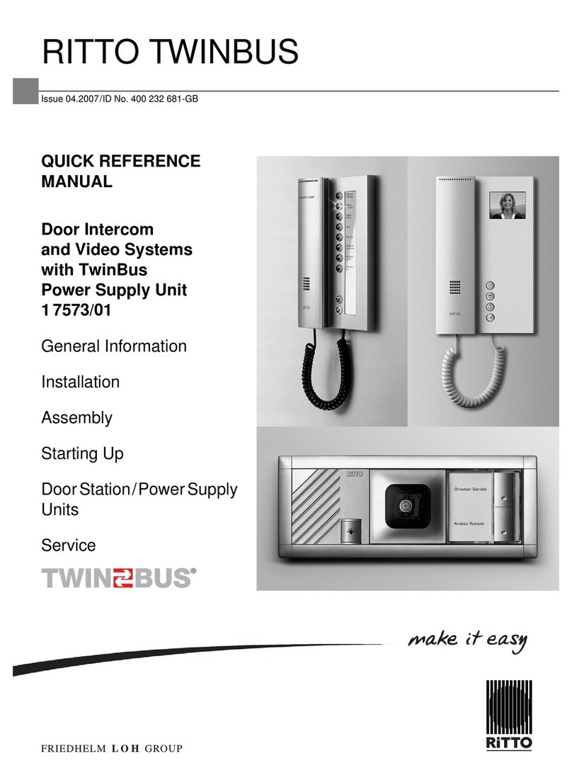
RITTO TWINBUS System Manual
Door intercom and video systems
based on bus technology
nInstallation
nStarting up
nOperation
nService
®
Titelseite_Systemhandbuch_EN_fin1 1 15.10.2007 13:01:43 Uhr
■Issue 8.2007 / Article no. 1 102850 Elkesan D10000738A 13.11.2019

2

Contents
3
Contents
Before continuing ... 7
General Information 9
1.1 Cable networks . . . . . . . . . . . . . . . . . . . . . . . . . . . . . . . . . . . . . . . . . . . . . . . . . . . . . . . . . . . . . . .9
1.1.1 Cable layout . . . . . . . . . . . . . . . . . . . . . . . . . . . . . . . . . . . . . . . . . . . . . . . . . . . . . . . . . . . .9
1.1.2 Maximum line lengths. . . . . . . . . . . . . . . . . . . . . . . . . . . . . . . . . . . . . . . . . . . . . . . . . . . . .9
1.1.3 Considerations when renovating . . . . . . . . . . . . . . . . . . . . . . . . . . . . . . . . . . . . . . . . . . .10
1.1.4 Connection to the mains. . . . . . . . . . . . . . . . . . . . . . . . . . . . . . . . . . . . . . . . . . . . . . . . . .10
1.1.5 Electrostatic charging . . . . . . . . . . . . . . . . . . . . . . . . . . . . . . . . . . . . . . . . . . . . . . . . . . . .10
1.2 The system bus . . . . . . . . . . . . . . . . . . . . . . . . . . . . . . . . . . . . . . . . . . . . . . . . . . . . . . . . . . . . . .10
1.3 Bus connector in the Portier modular door station. . . . . . . . . . . . . . . . . . . . . . . . . . . . . . . . .10
1.4 The video system . . . . . . . . . . . . . . . . . . . . . . . . . . . . . . . . . . . . . . . . . . . . . . . . . . . . . . . . . . . .11
1.5 Intended use . . . . . . . . . . . . . . . . . . . . . . . . . . . . . . . . . . . . . . . . . . . . . . . . . . . . . . . . . . . . . . . .12
1.6 Cleaning . . . . . . . . . . . . . . . . . . . . . . . . . . . . . . . . . . . . . . . . . . . . . . . . . . . . . . . . . . . . . . . . . . . .12
1.7 Handling equipment . . . . . . . . . . . . . . . . . . . . . . . . . . . . . . . . . . . . . . . . . . . . . . . . . . . . . . . . . .12
1.8 Directives/Conformity . . . . . . . . . . . . . . . . . . . . . . . . . . . . . . . . . . . . . . . . . . . . . . . . . . . . . . . . .12
1.9 Warranty. . . . . . . . . . . . . . . . . . . . . . . . . . . . . . . . . . . . . . . . . . . . . . . . . . . . . . . . . . . . . . . . . . . .12
Installation:
Assembly, connection and start-up 13
2.1 Door intercom systems without internal speech communication . . . . . . . . . . . . . . . . . . . . .13
2.1.1 Assembly and connection. . . . . . . . . . . . . . . . . . . . . . . . . . . . . . . . . . . . . . . . . . . . . . . . .13
2.1.2 Starting up . . . . . . . . . . . . . . . . . . . . . . . . . . . . . . . . . . . . . . . . . . . . . . . . . . . . . . . . . . . .13
2.2 Door intercom systems with internal speech communication . . . . . . . . . . . . . . . . . . . . . . . .19
2.2.1 Assembly and connection. . . . . . . . . . . . . . . . . . . . . . . . . . . . . . . . . . . . . . . . . . . . . . . . .19
2.2.2 Starting up . . . . . . . . . . . . . . . . . . . . . . . . . . . . . . . . . . . . . . . . . . . . . . . . . . . . . . . . . . . .19
2.3 Video-door intercom systems without internal speech communication . . . . . . . . . . . . . . . .23
2.3.1 Assembly and connection. . . . . . . . . . . . . . . . . . . . . . . . . . . . . . . . . . . . . . . . . . . . . . . . .23
2.3.2 Starting up . . . . . . . . . . . . . . . . . . . . . . . . . . . . . . . . . . . . . . . . . . . . . . . . . . . . . . . . . . . .23
2.4 Video-door intercom systems with internal speech communication. . . . . . . . . . . . . . . . . . .33
2.5 Indoor telephones, indoor video stations and intercom units . . . . . . . . . . . . . . . . . . . . . . . .33
2.5.1 TwinBus indoor telephone 1 7630 . . . . . . . . . . . . . . . . . . . . . . . . . . . . . . . . . . . . . . . . . .33
2.5.2 TwinBus comfort indoor telephone 1 7650. . . . . . . . . . . . . . . . . . . . . . . . . . . . . . . . . . . .38
2.5.3 TwinBus indoor video station 1 7857 . . . . . . . . . . . . . . . . . . . . . . . . . . . . . . . . . . . . . . . .46
2.5.4 TwinBus comfort indoor video station 1 7855. . . . . . . . . . . . . . . . . . . . . . . . . . . . . . . . . .52
2.5.5 TwinBus handsfree video intercom unit 1 7835 . . . . . . . . . . . . . . . . . . . . . . . . . . . . . . . .58
2.5.6 TwinBus comfort handsfree video intercom unit 1 7845. . . . . . . . . . . . . . . . . . . . . . . . . .68
2.5.7 TwinBus compact intercom unit 1 7132 . . . . . . . . . . . . . . . . . . . . . . . . . . . . . . . . . . . . . .76
2.5.8 TwinBus handsfree intercom unit 1 7230 . . . . . . . . . . . . . . . . . . . . . . . . . . . . . . . . . . . . .82
2.5.9 TwinBus signalling device 1 7930. . . . . . . . . . . . . . . . . . . . . . . . . . . . . . . . . . . . . . . . . . .85
2.5.10 TwinBus radio signalling device 1 7950 . . . . . . . . . . . . . . . . . . . . . . . . . . . . . . . . . . . . . .88
2.5.11 TwinBus intercom station 1 7133, 1 7134, 1 7135, 1 7136. . . . . . . . . . . . . . . . . . . . . . . .89

Contents
4
2.6 Accessories for indoor telephones, indoor video stations and intercom units . . . . . . . . . .92
2.6.1 Button 1 7636 . . . . . . . . . . . . . . . . . . . . . . . . . . . . . . . . . . . . . . . . . . . . . . . . . . . . . . . . . .92
2.6.2 TwinBus call interface relay 1 7646 . . . . . . . . . . . . . . . . . . . . . . . . . . . . . . . . . . . . . . . . .93
2.6.3 Button adapter 1 4645 . . . . . . . . . . . . . . . . . . . . . . . . . . . . . . . . . . . . . . . . . . . . . . . . . . .94
2.6.4 Radio transmitting printed circuit board 1 7656 . . . . . . . . . . . . . . . . . . . . . . . . . . . . . . . .95
2.6.5 TwinBus desktop console 1 7310. . . . . . . . . . . . . . . . . . . . . . . . . . . . . . . . . . . . . . . . . . .96
2.6.6 TwinBus desktop console 1 7311. . . . . . . . . . . . . . . . . . . . . . . . . . . . . . . . . . . . . . . . . . .96
2.6.7 TwinBus desktop console Video 1 7313. . . . . . . . . . . . . . . . . . . . . . . . . . . . . . . . . . . . . .96
2.6.8 TwinBus flush-mounted frame 1 7320, 1 7321, 1 7323 . . . . . . . . . . . . . . . . . . . . . . . . . .96
2.6.9 TwinBus coaxial connection adapter 1 4811 . . . . . . . . . . . . . . . . . . . . . . . . . . . . . . . . . .97
2.6.10 Flush-mounting radio transmitter 1 7856 . . . . . . . . . . . . . . . . . . . . . . . . . . . . . . . . . . . . .98
2.7 TwinBus power supply unit and accessories. . . . . . . . . . . . . . . . . . . . . . . . . . . . . . . . . . . . . .99
2.7.1 TwinBus power supply unit 1 7573. . . . . . . . . . . . . . . . . . . . . . . . . . . . . . . . . . . . . . . . . .99
2.7.2 TwinBus floor control unit 1 4585 . . . . . . . . . . . . . . . . . . . . . . . . . . . . . . . . . . . . . . . . . .101
2.7.3 TwinBus switching device 1 4981. . . . . . . . . . . . . . . . . . . . . . . . . . . . . . . . . . . . . . . . . .103
2.7.4 TwinBus door selector switch 1 4982 . . . . . . . . . . . . . . . . . . . . . . . . . . . . . . . . . . . . . . .106
2.7.5 TwinBus area coupler 1 4213. . . . . . . . . . . . . . . . . . . . . . . . . . . . . . . . . . . . . . . . . . . . .108
2.7.6 TwinBus line coupler 1 4214. . . . . . . . . . . . . . . . . . . . . . . . . . . . . . . . . . . . . . . . . . . . . .110
2.7.7 Video power supply unit 1 4874 . . . . . . . . . . . . . . . . . . . . . . . . . . . . . . . . . . . . . . . . . . .111
2.7.8 TwinBus video floor distributor 1 4812 . . . . . . . . . . . . . . . . . . . . . . . . . . . . . . . . . . . . . .112
2.7.9 TwinBus video line distributor 1 4813. . . . . . . . . . . . . . . . . . . . . . . . . . . . . . . . . . . . . . .113
2.7.10 TwinBus line switch 1 4814 . . . . . . . . . . . . . . . . . . . . . . . . . . . . . . . . . . . . . . . . . . . . . .114
2.7.11 TwinBus camera selector switch 1 4915 . . . . . . . . . . . . . . . . . . . . . . . . . . . . . . . . . . . .117
2.7.12 Power supply unit 1 6371 . . . . . . . . . . . . . . . . . . . . . . . . . . . . . . . . . . . . . . . . . . . . . . . .120
2.7.13 Mains transformer 1 6476. . . . . . . . . . . . . . . . . . . . . . . . . . . . . . . . . . . . . . . . . . . . . . . .122
2.7.14 Mains transformer 1 6477. . . . . . . . . . . . . . . . . . . . . . . . . . . . . . . . . . . . . . . . . . . . . . . .123
2.7.15 TwinBus door handsfree amplifier 1 4680 . . . . . . . . . . . . . . . . . . . . . . . . . . . . . . . . . . .124
2.7.16 TwinBus telecommunication adapter a/b 1 4685 . . . . . . . . . . . . . . . . . . . . . . . . . . . . . .126
2.8 Door stations . . . . . . . . . . . . . . . . . . . . . . . . . . . . . . . . . . . . . . . . . . . . . . . . . . . . . . . . . . . . . . .132
2.8.1 Modular Portier door station . . . . . . . . . . . . . . . . . . . . . . . . . . . . . . . . . . . . . . . . . . . . . .132
2.8.2 Compact door station Entravox 1 8401 - 1 8404 . . . . . . . . . . . . . . . . . . . . . . . . . . . . . .134
2.8.3 Compact door station Entravox Video 1 8431 - 1 8432 . . . . . . . . . . . . . . . . . . . . . . . . .135
2.8.4 Verrano glass door station 1 8301–1 8304, 1 8311–1 8314, 1 8321–1 8324 and
1 8331–1 8334 . . . . . . . . . . . . . . . . . . . . . . . . . . . . . . . . . . . . . . . . . . . . . . . . . . . . . . . .138
2.8.5 TwinBus built-in loudspeaker 1 4921 . . . . . . . . . . . . . . . . . . . . . . . . . . . . . . . . . . . . . . .141
2.8.6 TwinBus extension unit 1 4923. . . . . . . . . . . . . . . . . . . . . . . . . . . . . . . . . . . . . . . . . . . .143
2.8.7 Staircase door station 1 8201. . . . . . . . . . . . . . . . . . . . . . . . . . . . . . . . . . . . . . . . . . . . .144
2.8.8 Built-in colour camera 1 4883. . . . . . . . . . . . . . . . . . . . . . . . . . . . . . . . . . . . . . . . . . . . .149
2.8.9 Colour video camera 1 7652. . . . . . . . . . . . . . . . . . . . . . . . . . . . . . . . . . . . . . . . . . . . . .150
2.8.10 Coding module 1 4764 . . . . . . . . . . . . . . . . . . . . . . . . . . . . . . . . . . . . . . . . . . . . . . . . . .151
2.8.11 Access module 1 4768 . . . . . . . . . . . . . . . . . . . . . . . . . . . . . . . . . . . . . . . . . . . . . . . . . .152

Contents
5
Operation 157
3.1 Door intercom systems without internal voice communication. . . . . . . . . . . . . . . . . . . . . .158
3.2 Door intercom systems with internal voice communication. . . . . . . . . . . . . . . . . . . . . . . . .158
3.3 Video-door intercom systems without internal voice communication . . . . . . . . . . . . . . . .158
3.4 Video-door intercom systems with internal voice communication . . . . . . . . . . . . . . . . . . .158
3.5 Indoor telephones, indoor video stations and intercom units . . . . . . . . . . . . . . . . . . . . . . .159
3.5.1 TwinBus indoor telephone 1 7630 . . . . . . . . . . . . . . . . . . . . . . . . . . . . . . . . . . . . . . . . .159
3.5.2 TwinBus comfort indoor telephone 1 7650. . . . . . . . . . . . . . . . . . . . . . . . . . . . . . . . . . .160
3.5.3 TwinBus colour indoor video station 1 7857. . . . . . . . . . . . . . . . . . . . . . . . . . . . . . . . . .162
3.5.4 TwinBus comfort indoor video station 1 7855. . . . . . . . . . . . . . . . . . . . . . . . . . . . . . . . .163
3.5.5 TwinBus handsfree video intercom unit 7835. . . . . . . . . . . . . . . . . . . . . . . . . . . . . . . . .166
3.5.6 TwinBus comfort handsfree video intercom unit 1 7845. . . . . . . . . . . . . . . . . . . . . . . . .170
3.5.7 TwinBus compact intercom unit 1 7132 . . . . . . . . . . . . . . . . . . . . . . . . . . . . . . . . . . . . .173
3.5.8 TwinBus handsfree intercom unit 1 7230 . . . . . . . . . . . . . . . . . . . . . . . . . . . . . . . . . . . .174
3.5.9 TwinBus signalling device 1 7930. . . . . . . . . . . . . . . . . . . . . . . . . . . . . . . . . . . . . . . . . .175
3.5.10 TwinBus radio signalling device 1 7950 . . . . . . . . . . . . . . . . . . . . . . . . . . . . . . . . . . . . .176
3.5.11 TwinBus intercom station 1 7133, 1 7134, 1 7135, 1 7136. . . . . . . . . . . . . . . . . . . . . . .177
3.6 Accessories for indoor telephones, indoor video stations and intercom units . . . . . . . . .178
3.6.1 Button 1 7636 . . . . . . . . . . . . . . . . . . . . . . . . . . . . . . . . . . . . . . . . . . . . . . . . . . . . . . . . .178
3.6.2 TwinBus call interface relay 1 7646 . . . . . . . . . . . . . . . . . . . . . . . . . . . . . . . . . . . . . . . .178
3.6.3 Button adapter 1 4645 . . . . . . . . . . . . . . . . . . . . . . . . . . . . . . . . . . . . . . . . . . . . . . . . . .178
3.6.4 Radio transmitting printed circuit board 1 7656 . . . . . . . . . . . . . . . . . . . . . . . . . . . . . . .178
3.6.5 TwinBus desktop console 1 7310. . . . . . . . . . . . . . . . . . . . . . . . . . . . . . . . . . . . . . . . . .178
3.6.6 TwinBus desktop console 1 7311. . . . . . . . . . . . . . . . . . . . . . . . . . . . . . . . . . . . . . . . . .178
3.6.7 TwinBus desktop console Video 1 7313. . . . . . . . . . . . . . . . . . . . . . . . . . . . . . . . . . . . .178
3.6.8 TwinBus flush-mounted frame 1 7320, 1 7321, 1 7322 . . . . . . . . . . . . . . . . . . . . . . . . .178
3.6.9 TwinBus coaxial connection adapter 1 4811. . . . . . . . . . . . . . . . . . . . . . . . . . . . . . . . .178
3.6.10 Flush-mounting radio transmitter 1 7856 . . . . . . . . . . . . . . . . . . . . . . . . . . . . . . . . . . . .178
3.7 TwinBus power supply unit and accessories. . . . . . . . . . . . . . . . . . . . . . . . . . . . . . . . . . . . .179
3.7.1 TwinBus power supply unit 1 7573. . . . . . . . . . . . . . . . . . . . . . . . . . . . . . . . . . . . . . . . .179
3.7.2 TwinBus floor control unit 1 4585 . . . . . . . . . . . . . . . . . . . . . . . . . . . . . . . . . . . . . . . . . .179
3.7.3 TwinBus switching device 1 4981. . . . . . . . . . . . . . . . . . . . . . . . . . . . . . . . . . . . . . . . . .179
3.7.4 TwinBus door selector switch 1 4982. . . . . . . . . . . . . . . . . . . . . . . . . . . . . . . . . . . . . . .179
3.7.5 TwinBus area coupler 1 4213. . . . . . . . . . . . . . . . . . . . . . . . . . . . . . . . . . . . . . . . . . . . .179
3.7.6 TwinBus line coupler 1 4214. . . . . . . . . . . . . . . . . . . . . . . . . . . . . . . . . . . . . . . . . . . . . .179
3.7.7 Video power supply unit 1 4874 . . . . . . . . . . . . . . . . . . . . . . . . . . . . . . . . . . . . . . . . . . .179
3.7.8 TwinBus video floor distributor 1 4812 . . . . . . . . . . . . . . . . . . . . . . . . . . . . . . . . . . . . . .179
3.7.9 TwinBus video line distributor 1 4813. . . . . . . . . . . . . . . . . . . . . . . . . . . . . . . . . . . . . . .179
3.7.10 TwinBus line switch 1 4814 . . . . . . . . . . . . . . . . . . . . . . . . . . . . . . . . . . . . . . . . . . . . . .179
3.7.11 TwinBus camera selector switch 1 4915 . . . . . . . . . . . . . . . . . . . . . . . . . . . . . . . . . . . .179
3.7.12 Power supply unit 1 6371 . . . . . . . . . . . . . . . . . . . . . . . . . . . . . . . . . . . . . . . . . . . . . . . .179
3.7.13 Mains transformer 1 6476. . . . . . . . . . . . . . . . . . . . . . . . . . . . . . . . . . . . . . . . . . . . . . . .179
3.7.14 Mains transformer 1 6477. . . . . . . . . . . . . . . . . . . . . . . . . . . . . . . . . . . . . . . . . . . . . . . .179
3.7.15 TwinBus door handsfree amplifier 1 4680 . . . . . . . . . . . . . . . . . . . . . . . . . . . . . . . . . . .179
3.7.16 TwinBus telecommunication adapter a/b 1 4685 . . . . . . . . . . . . . . . . . . . . . . . . . . . . . .180

Contents
6
3.8 Door stations . . . . . . . . . . . . . . . . . . . . . . . . . . . . . . . . . . . . . . . . . . . . . . . . . . . . . . . . . . . . . . .181
3.8.1 Modular Portier door station . . . . . . . . . . . . . . . . . . . . . . . . . . . . . . . . . . . . . . . . . . . . . .181
3.8.2 Compact door station Entravox . . . . . . . . . . . . . . . . . . . . . . . . . . . . . . . . . . . . . . . . . . .181
3.8.3 Compact door station Entravox Video . . . . . . . . . . . . . . . . . . . . . . . . . . . . . . . . . . . . . .181
3.8.4 Verrano glass door station . . . . . . . . . . . . . . . . . . . . . . . . . . . . . . . . . . . . . . . . . . . . . . .181
3.8.5 TwinBus built-in loudspeaker 1 4921 . . . . . . . . . . . . . . . . . . . . . . . . . . . . . . . . . . . . . . .181
3.8.6 TwinBus extension unit 1 4923. . . . . . . . . . . . . . . . . . . . . . . . . . . . . . . . . . . . . . . . . . . .181
3.8.7 Staircase door station 1 8201. . . . . . . . . . . . . . . . . . . . . . . . . . . . . . . . . . . . . . . . . . . . .182
3.8.8 Built-in colour camera 1 4883. . . . . . . . . . . . . . . . . . . . . . . . . . . . . . . . . . . . . . . . . . . . .182
3.8.9 Colour video camera 1 7652. . . . . . . . . . . . . . . . . . . . . . . . . . . . . . . . . . . . . . . . . . . . . .182
3.8.10 Coding module 1 4764 . . . . . . . . . . . . . . . . . . . . . . . . . . . . . . . . . . . . . . . . . . . . . . . . . .182
3.8.11 Access module 1 4768 . . . . . . . . . . . . . . . . . . . . . . . . . . . . . . . . . . . . . . . . . . . . . . . . . .182
Service speech 183
4.1 Measuring points. . . . . . . . . . . . . . . . . . . . . . . . . . . . . . . . . . . . . . . . . . . . . . . . . . . . . . . . . . . .183
4.2 Service indicators . . . . . . . . . . . . . . . . . . . . . . . . . . . . . . . . . . . . . . . . . . . . . . . . . . . . . . . . . . .184
4.3 Troubleshooting table. . . . . . . . . . . . . . . . . . . . . . . . . . . . . . . . . . . . . . . . . . . . . . . . . . . . . . . .185
Index 190

Before continuing ...
7
Before continuing ...
Before continuing ...
Using this system manual
This system manual provides all the information necessary for planning, installing and operating a TwinBus door
intercom system. In order to find the information requiredquickly, the chapters have been organized according to the
following groups of customers:
In the Installation chapter, basic information is provided by means of general examples. Detailed technical
specifications on the individual devices supplements the information.
Please keep this system manual on hand for later use.
Explanation of the symbols used
Indication of risks:
Important information:
Circuit diagram symbols
Chapter Customer group
1. General Information All customer groups
2. Installation: assembly, connection and start-up Electricians and installation technicians
3. Operation Users
4. Service After-sales service personnel
Danger!
Type and source of the danger
This danger symbol indicates the risk of personal injury.
Caution!
Type and source of the danger
This symbol indicates the risk of equipment, environment or other property damage.
Note:
This symbol does not represent a safety note. It identifies information to better understand the
respective processes.
This symbol indicates an acoustic signal issued by a device should be observed. The length of the signal
indicates the acknowledgement of settings.
This circuit diagram symbol indicates a twisted pair of wires.
This circuit diagram symbol indicates that the line screening sheaths must be connected across the joints.

Before continuing ...
Before continuing ...
8
List of abbreviations
ET Floor line
ED Apartment button
TÖ Door opener
LWChime type, e.g. gong
UV Subdistribution
Terminal designations
a Bus terminal
b Bus terminal
ED Apartment button
ED Apartment button
a1 Main bus line 1
a2 Main bus line 2
a3 Main bus line 3
Va Bus terminal, video bus
Vb Bus terminal, video bus
LWChime type, e.g. gong
TV Door connection
NV Power supply connection
Information on article numbers
The article numbers of RITTO products are made up of three components. For example, 1 7630 70
1 7630 xx Device: TwinBus indoor telephone
7 x Colour: white
x 0 Device index
This document only specifies information on the respective device. Please refer to the manual for the colours
available and the current device versions.

General Information
General Information
9
1
General Information
1.1 Cable networks
Existing lines can be used as bus lines. We recommend the following, commercially available telecommunication
lines:
Telecommunication line J-Y (St) Y
Telecommunication line J-2Y (z) Y with strain-relief
Telecommunication grounding cable, longitudinally and transversally waterproof
For more information, please refer to the planning manual.
1.1.1 Cable layout
It is recommended to lay the bus line from subscriber to subscriber and to connect it to the connectionterminal on the
device.
All the line screening sheaths must be connected across the joints and laid to Terminal b on the TwinBus power
supply unit. Please use appropriate locally provided terminals for this.
The stranded video line Va/Vb can generally be laid in the cable with the screened a/b lines.
In order to fulfil the general safety requirements for telecommunication systems complying to VDE 0800 and prevent
disturbances on the lines, ensure that the mains voltage and SELV (TwinBus line) are laid separately. A clearance of
10 cm must be maintained for the installation. In the case of a common line cabling, a separating webbing must be
inserted in the installation channels.
The bus lines must be terminated with terminal resistors.
Please follow the installation instructions for the indoor video stations 1 7855, 1 7857 or the handsfree video intercom
units 1 7835 and 1 7845.
1.1.2 Maximum line lengths
The loop resistance of each TwinBus line must not exceed max. 20 Ohm. This results in the following maximum line lengths:
Line lengths for 75 ΩCOAX lines
Caution!
Malfunctions due to strong magnetic fields
No other devices with strong magnetic field (contactors, transformers, etc.) may be installed in the
direct vicinity of the power supply unit and additional devices. Malfunctions could be caused by
induced voltage peaks.
Wire diameter in mm 0,8 0,6
Resistance in Ohm/m 0,0349 0,0621
Line lengths between TwinBus power supply unit 1 7573 and indoor telephone or indoor
video station 280 m 160 m
Line lengths between TwinBus power supply unit 1 7573 and door unit (lighting) 60 m 30 m
Line lengths between TwinBus power supply unit 1 7573 and door openers up to 8V/1A 50 m 30 m
Line lengths between power supply unit 1 4874 and indoor video station 100 m 60 m
Line lengths between mains transformer 1 6477 and indoor video station 50 m 35 m
Line lengths between mains transformer 1 6477 and camera module 35 m 25 m
Line lengths between mains transformer 1 6477 and camera module 150 m 100 m
Line lengths between mains transformer 1 6477 and built-in camera 40 m 20 m
Cable type Line lengths
3/S – 75 250 m
1.1/7.3 600 m

General Information
10
General Information
1.1.3 Considerations when renovating
If commercially available doorbells are used, they must not have a contact transition resistance in excess of 10 Ohm.
1.1.4 Connection to the mains
Please note that a 230 V/AC power supply is required for the power supply units and mains transformers which are
not explicitly depicted in the block diagrams.
1.1.5 Electrostatic charging
1.2 The system bus
Thepowersupplyunitandadditionaldevicesare connected via the system bus. The system bus connector, enclosed
with each additional device, is used for this purpose.
1.3 Bus connector in the Portier modular door station
The door station modules are connected to the bus connectors one under the other.
Note:
In the case of existing YR cables, all the free wires on the TwinBus power supply unit must be laid
as screening to Terminal b.
Caution!
Equipment damage through overvoltage or short circuiting
Equipment damage can occur through overvoltage or short circuiting. Connection must be made to
a 230 V~±10% mains power outlet. The power must be fed via an intrinsic line safety switch with
max.10 A.
Caution!
Risk of equipment damage through static electricity (ESD)
Static electricity could destroy equipment if direct contact is made with the printed circuit boards.
Discharge electrostatic charges before touching the equipment.
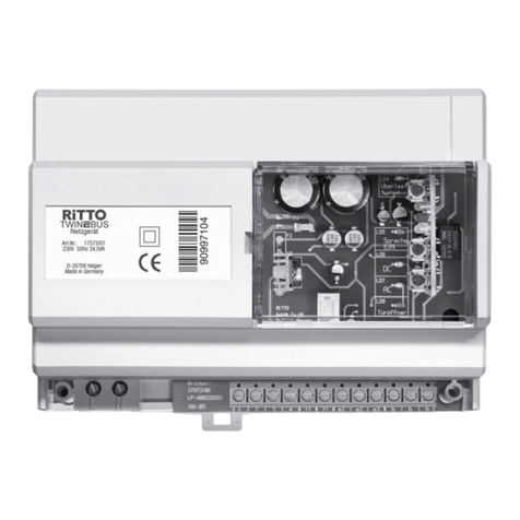
1. TwinBus power supply unit 1 7573
2. System bus connector
3. TwinBus additional device
The additional devices receive their power supply via the
system bus.
If the devices are installed on several mounting rails, the
bus connector 1 6907 is used instead of the system bus
connector.
Connection is made from the right-hand system bus
connection of the device to the left-hand system bus
connection of the following device.
The wire of the bus connector in the door station marked
red must be attached to the pin labelled "red" on the
board. As a result, the door station modules are
numbered identically. The wire marked red is identified in
the respective circuit diagram by a "*".
!
00341-0
RiTTO

General Information
11
General Information
1.4 The video system
Installation requirements for video cameras
A camera can only view a certain area. In order for the visitor who has just rung to be monitored, for example, the
camera must be appropriately installed.
The surveillance area varies according to the angle the camera module is set.
The installation height is approx. 1.5 to 1.6 m.
Theareasurveilledmust be wellilluminated,alsoatnight. Ifnecessary,appropriatelightingmustalso be installed.
We recommend positioning an external light about 1 m above the camera. It should be an incandescent bulb of
at least 40 W.
The camera must not be pointed towards the source of light (sun, lighting, reflection, etc.).
Terminal resistor
Circuit diagram:terminal resistor for mixed systems.
A indoor video station as the last device in the line
* Terminal resistor: ON
B indoor video station as the last device in the line
** Terminal resistor: OFF
Note:
You must switch on the terminal resistor if the indoor video station 1 7857 or 1 7855 or handsfree
video intercom unit 1 7835 or 1 7845 you want to install is the last device in the video bus line.
If the last device installed in the video bus line is an indoor video station 1 7815 or 1 7825, manually
use a 100 Ωresistor 1 7832.
Caution!
Reduced image quality
Incorrectly set terminal resistors will lead to reduced image quality.
1 7857
1 7857
Va Vb Va Vb Va Vb
))
*
Va Vb Va Vb Va Vb
1 7815/25
1 7815/25
S0121-0

General Information
12
General Information
1.5 Intended use
The RITTO door intercom is a system devised for controlling access and internal communication inside residential
buildings.
Any other use is considered unintended use. The manufacturer is not deemed liable for any damage resulting from
unintended use. The risk, in this case, is assumed solely by the installation technician.
Intended use also includes observing the manufacturer's regulations concerning use and maintenance. The system
may only be installed and serviced by persons familiar with it and informed of the risks involved.
1.6 Cleaning
The surfaces of the TwinBus devices can become dirty due to environmental influences and frequent use. The
surfaces should only be cleaned with a damp cloth and suitable, mild household cleaning agent.
Stainless steel surfaces should be cleaned regularly with a commercially available stainless steel cleaning agent to
prevent flash rust from forming.
Make certain that the plastic parts of the door station (e.g. name labels) do not come into contact with the cleaner.
Observe the information provided by the cleaning agent manufacturer.
1.7 Handling equipment
The devices could be damaged through static electricity. Therefore, static must be discharged from the body before
touching printed circuit boards by contact with a grounded connection.
1.8 Directives/Conformity
All RITTO TwinBus devices have been constructed according to the following directives:
EU Directive on "Electromagnetic Compatibility" 89/336/EEC and 2004/108/EC, respectively (complying to the
currently valid version).
Directives on low-voltage 72/23/EEC (complying to the currently valid version).
RITTO TwinBus devices bear the CE approval label. Conformity has been certified. The corresponding documents
are held by the manufacturer.
1.9 Warranty
The general terms of business implemented by RITTO GmbH & Co. KG apply.

Installation: Assembly, connection and start-up
13
Installation
2
Installation:
Assembly, connection and start-up
This chapter contains all the information that is needed to install a door intercom system.
2.1 Door intercom systems without internal speech communication
The assembly, connection and start-up of a TwinBus system depends on the design of the system and the type of
TwinBus devices that are used. Information on how to carry out the work can be found in the following. More
information can be found in the descriptions of the individual TwinBus devices.
2.1.1 Assembly and connection
2.1.2 Starting up
The information on the initial start-up and expansion of a TwinBus door intercom system can be found on the pages
that follow.
One or multi-family residence with one to three main bus lines
Block diagram:one or multi-family residence with one to three main bus lines.
Danger!
Electrical voltage
Risk of electric shock.
Risk of burning.
Damage to equipment and malfunctions.
Countermeasures:
Isolate all live cables before starting the work.
Protect the switched-off lines from being mistakenly switched on again.
Test that the power is off. Earth and short-circuit.
Cover up neighbouring live parts.
All work and electrical connections must comply with the national regulations of the respective
country (e.g. the VDE regulations in Germany) and be carried out by appropriately trained
experts.
4
2
RiTTO
2
2
2
222
222
22
RiTTO
2
2
2
2

Installation
Installation: Assembly, connection and start-up
14
* Please observe the red marking - refer to "Bus connector in the Portier modular door station" page ☞ 10.
Circuit diagram: one or multi-family residence with one to three main bus lines.
Starting up
Operation Device
1. Switch on Customer line safety switch
2. Deactivate adjustment protection1)
1) Deactivated by the contractor.
TwinBus power supply unit 1 7573
3. Programming the main doorbell2)
2) For more information, refer to "TwinBus indoor telephone 1 7630" page ☞ 33.
Assign door station and intercoms
4. Adjust door opening time TwinBus power supply unit 1 7573, default value 3 s
5. Activate adjustment protection if
required TwinBus power supply unit 1 7573
RiTTO

Installation: Assembly, connection and start-up
15
Installation
One or multiple-family residence with extension to two door stations
Block diagram: one or multiple-family residence with extension to two door stations.
* Please observe the red marking - refer to "Bus connector in the Portier modular door station" page ☞ 10.
Circuit diagram: one or multiple-family residence with extension to two door stations.
2
2
2
2
2
2
RiTTO
RiTTO
2
2
2
2
2
2
2
2
2
2
4242
RiTTO
RiTTO

Installation
Installation: Assembly, connection and start-up
16
Starting up
Multi-family and office building with separate floor access door stations
Block diagram: multi-family and office building with separate floor access door stations.
Operation Device
1. Switch on Customer line safety switch
2. Deactivate1) adjustment protection
1) Deactivated by the contractor.
TwinBus power supply unit 1 7573
3. Activate door station Door selector switch 1 4982
4. Programming the main doorbell2)
2) More information can be found in the indoor video station “Start-up” section starting on page☞ 46.
Assign door station and intercoms
5. Adjust door opening time TwinBus power supply unit 1 7573, default value 3 s
6. Activate adjustment protection if
required TwinBus power supply unit 1 7573
4
2
1 7573
2
2
2
1 4585
1 7573
4
1 7630 1 7630
RiTTO
RiTTO
RiTTO
1 4760
1 4751
ED
2
2
1 7573
4
2
1 7630 1 7630
RiTTO
RiTTO
1 4760
1 4751
2
2
RiTTO
1 4760
1 4754
1 4754
2
ED
2
1 7630
ED
2
1 7630
ED
2
1 7630 1 7630
ET2
ET1
2
1 4585
a1 a2
230 V
230 V
2
230 V
B0007-1

Installation: Assembly, connection and start-up
17
Installation
* Please note the red mark – see “Bus connections in the door station” on page ☞ 10.
Circuit diagram: multi-family and office building with separate floor access door stations.
RiTTO
RiTTO
RiTTO

Installation
Installation: Assembly, connection and start-up
18
Starting up
Operation Device
1. Switch on Customer line safety switch
2. Delete power supply unit memory TwinBus power supply units 1 7573 for main bus line and floor lines
3. Deactivate adjustment protection1)
1) Deactivated by the contractor.
TwinBus power supply units 1 7573 for main bus line and floor lines
4. Activate self-programming mode2)
2) Operations 3 to 8 must be repeated for each floor line.
Floor control unit 1 4585
5. Activate door station3)
3) Optional.
Door selector switch 1 4982
6. Programming the main doorbell4)
4) More information can be found in the indoor telephone “Start-up” section starting on page☞ 33.
Assign main door station and intercoms to main bus line and floor line
7. Deactivate self-programming mode Floor control unit 1 4585
8. Program apartment doorbells4) Floor door station and intercom units
9. Program switching device3) Switching device 1 4981
10. Adjust door opening time TwinBus power supply unit 1 7573 at floor and main door, default value
3 s
11. Activate adjustment protection if
required TwinBus power supply unit 1 7573 for main bus line and floor lines

Installation: Assembly, connection and start-up
19
Installation
2.2 Door intercom systems with internal speech communication
The assembly, connection and start-up of a TwinBus system depends on the design of the system and the type of
TwinBus devices that are used. Information on how to carry out the work can be found in the following. More
information can be found in the descriptions of the individual TwinBus devices.
2.2.1 Assembly and connection
2.2.2 Starting up
The information on the initial start-up and expansion of a TwinBus door intercom system can be found on the pages
that follow.
One or multi-family residence with one main bus line
Block diagram: one or multi-family residence with one main bus line.
Danger!
Electrical voltage
Risk of electric shock.
Risk of burning.
Damage to equipment and malfunctions.
Countermeasures:
Isolate all live cables before starting the work.
Protect the switched-off lines from being mistakenly switched on again.
Test that the power is off. Earth and short-circuit..
Cover up neighbouring live parts.
All work and electrical connections must comply with the national regulations of the respective
country (e.g. the VDE regulations in Germany) and be carried out by appropriately trained
experts.
RiTTO
1 4760
1 4751
2
2
2
1 7573
4
2
1 7650
1 7650
1 7650
230 V B0018-1

Installation
Installation: Assembly, connection and start-up
20
* Please note the red mark – see “Bus connections in the door station” on page ☞ 10.
Circuit diagram: one or multi-family residence with one main bus line
Starting up
Multi-family and office building with separate floor access door stations
Block diagram: multi-family and office building with separate floor access door stations.
Operation Device
1. Switch on Customer line safety switch
2. Deactivate adjustment protection1)
1) Deactivated by the contractor.
TwinBus power supply unit 1 7573
3. Programming the main doorbell2)
2) More information can be found in the indoor telephone “Start-up” section starting on page☞ 33.
Assign door station and intercoms
4. Program internal call numbers Intercom units with internal communication
5. Adjust door opening time TwinBus power supply unit 1 7573, default value 3 s
6. Activate adjustment protection if
required TwinBus power supply unit 1 7573
RiTTO
4
2
1 7573
2
2
1 4585
1 7573
4
RiTTO
RiTTO
RiTTO
1 4760
1 4751
ED
2
1 7573
4
2
1 7650 1 7650
22
RiTTO
RiTTO
1 4760
1 4751
2
2
RiTTO
1 4760
1 4754
1 4754
2
ED
2
1 7630
ED
2
1 7630
ED
2
1 7630 1 7630
ET2
2
1 4585
a1 a2
230 V
230 V
2
230 V
1 7650 1 7650
22
ET1
B0016-1
Table of contents
Other RiTTO Intercom System manuals
