Rivet King RK-50SP User manual

Read All Safety Rules and Instructions Carefully
Save this manual for Future Reference
Operating Instructions
SPIN-PULL THREADED INSERT TOOL

1
1
1
1
RK50SP-1-832
RK50SP-1-1220
R
RK50SP-1-1213
mandrel 8-32UNC
mandrel ½-20UNC
mandrel
mandrel ½-13UNC
1
1
1
1
1
1
RK50SP-1-1024
RK50SP-1-M407
mandrel 10-24UNC
mandrel M4x0.7
1
1
1
1
RK50SP-1-1032
RK50SP-1-M508
mandrel 10-32UNF
mandrel M5x0.8
1
1
1
1
RK50SP-1-1420
RK50SP-1-M61
mandrel 1/4-20UNC
mandrel M6X1.0
1
1
1
1
1
RK50SP-1-1428
RK50SP-1-M71
RK50SP-1-M1015
mandrel 1/4-28UNF
mandrel M7X1.0
mandrel M10X1.50
1
1
1
1
1
1
RK50SP-1-51618
RK50SP-1-M81
RK50SP-1-M12125
mandrel 5/16-18UNC
mandrel M8X1.0
mandrel M12X1.25
1
1
1
1
1
1
RK50SP-1-51624
RK50SP-1-M8125
RK50SP-1-M1215
mandrel 5/16-24UNF
mandrel M8X1.25
mandrel M12X1.50
1
1
1
1
1
1
RK50SP-1-3816
RK50SP-1-M101
RK50SP-1-M12175
mandrel 3/8-16UNC
mandrel M10X1.0
mandrel M12X1.75
1
1
1
1
1
2
2
RK50SP-1-3824
RK50SP-1-M10125
RK50SP
RK50SP-2-1213
mandrel 3/8-24UNF
mandrel M10X1.25
nose piece
nose piece ½-13UNC
1
1
1
1
2
2
RK50SP-2-832
RK50SP-2-1220
nose piece 8-32UNC
nose piece ½-20UNC
1
1
2
2
2
RK50SP-2-1024
RK50SP-2-M407
RK50SP-2-1032
RK50SP-2-M508
RK50SP-2-M12125
RK50SP-2-1420
RK50SP-2-M61
RK50SP-2-M1215
RK50SP-2-1428
RK50SP-2-M71
RK50SP-2-M12175
RK50SP-2-51618
RK50SP-2-M81
RK50SP-2-51624
RK50SP-2-M8125
RK50SP-3
RK50SP-4-6
RK50SP-7
RK50SP-8
RK50SP-9
RK50SP-10
RK50SP-11
RK50SP-14
RK50SP-17
RK50SP-18
RK50SP-20
RK50SP-21
RK50SP-23
RK50SP-26
RK50SP-27
RK50SP-28
RK50SP-29
RK50SP-30
RK50SP-31
RK50SP-32
RK50SP-33
RK50SP-34
RK50SP-37
RK50SP-38
RK50SP-39
RK50SP-40
RK50SP-43
RK50SP-45
RK50SP-46
RK50SP-48
RK50SP-49
RK50SP-51
RK50SP-52
RK50SP-53
RK50SP-54
RK50SP-55
RK50SP-56
RK50SP-57
RK50SP-58
RK50SP-59
RK50SP-60
RK50SP-62
RK50SP-63
RK50SP-67
RK50SP-68
RK50SP-69
RK50SP-70
RK50SP-72
RK50SP-73
RK50SP-76
RK50SP-77
RK50SP-78
RK50SP-79
RK50SP-2-3816
RK50SP-2-M101
RK50SP-2-3824
RK50SP-2-M10125
RK50SP-2-M1015
nose piece 10-24UNC
nose piece M4X0.7
nose piece M10X1.50
1
1
1
2
2
2
nose piece 10-32UNF
nose piece M5X0.8
nose piece M12X1.25
1
1
1
2
2
2
nose piece 1/4-20UNC
nose piece M6X1.0
nose piece M12X1.50
1
1
1
2
2
2
nose piece 1/4-28UNF
nose piece M7X1.0
nose piece M12X1.75
1
1
1
2
2
nose piece 5/16-18UNC
nose piece M8X1.0
1
1
2
2
nose piece 5/16-24UNF
nose pieceM8X1.25
1
1
2
2
nose piece 3/8-16UNC
nose pieceM10X1.0
1
1
2
2
nose piece 3/8-24UNF
nose piece M10X1.25
1
1
3set nut 1
4~6 front sleeve complete 1
7security part 1
8spring holder 1
9spring 1
10 pin cylindrical 1
11 lock nut 1
14 hydraulic plunger complete 1
17 buffer ring 1
18 cap screw 1
20 hanger 1
21 hydraulic body 1
23 guide ring 1
26 sleeve 1
27 protective sleeve 1
28 pin cylindrical 1
29 compression spring 1
30 compression spring 1
31 rear screwed joint 1
32 ring for compression spring 1
33 muffler 1
34 push button 1
37 bottom ring 1
38 pneumatic plunger 1
39 pneumatic cylinder 1
40 cover ring 1
43 coupling for pressure gauge 1
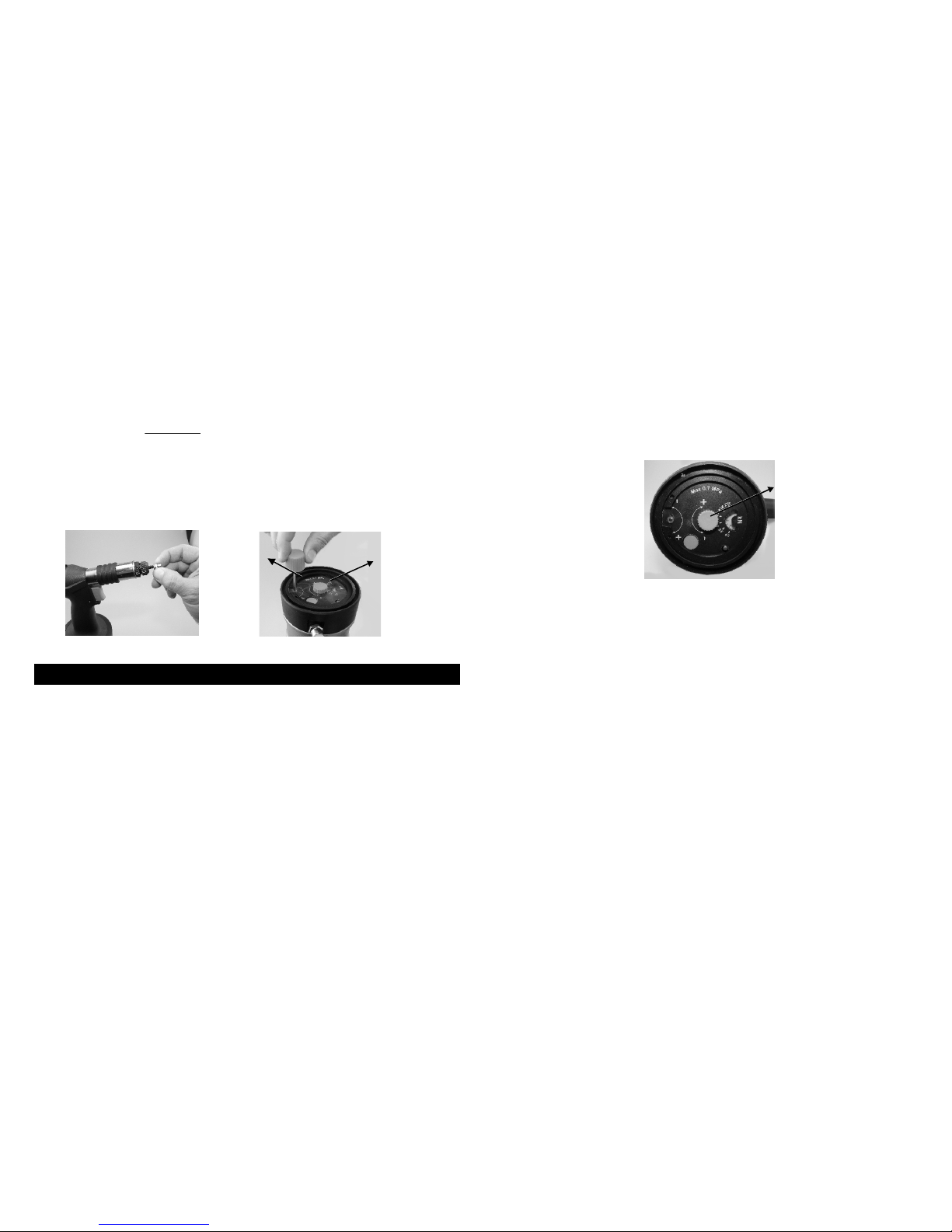
45 pressure gauge 1
46 oil level indicator 1
48 pressure relief valve 1
49 pressure regulation valve 1
51 retaining ring 1
52 pressure regulation screw 1
53 covering 1
54 retaining ring 1
55 bottom ring 1
56 union coupling 1
57 connecting bolt 2
58 copper washer for connecting bolt 2
59 cap nut for connecting bolt 2
60 bolt below valve pin 1
62 sleeve for needle valve 1
63 muffler 4
67 valve pin 1
68 pin cylindrical 1
69 eccentric trigger 1
70 trigger 1
72 needle valve for time of return 1
73 cap screw 1
76 plastic board 1
77 compression spring 1
78 tapping screw 1
79 adjusting ring 1
PART SOLD SEPARATELYPART SOLD SEPARATELY
Diagram No. Part No. Description Required No.
12 RK50SP
-12
RK50SP-13
RK50SP-15
RK50SP-16
RK50SP-19
RK50SP-22
RK50SP-24
RK50SP-25
RK50SP-35
RK50SP-36
RK50SP-41
RK50SP-42
RK50SP-44
RK50SP-47
RK50SP-50
RK50SP-61
RK50SP-64
RK50SP-66
RK50SP-71
RK50SP-74
RK50SP-75
RK50SP-81
o-ring 1
13 o-ring 1
15 o-ring 1
16 lip seal 1
19 o-ring 1
22 lip seal 1
24 o-ring 1
25 o-ring 1
35 lip seal 1
36 o-ring 1
41 o-ring 1
42 o-ring 1
44 o-ring 1
47 o-ring 1
50 o-ring 2
61 o-ring 1
64 o-ring 2
66 u-ring 3
71 o-ring 1
74 o-ring 1
75 o-ring 1
81 o-ring 1
Complete Seal KitComplete Seal Kit
THE SAFETY WARNINGS BELOW CANNOT COVER ALL POSSIBLE SITUATIONS THAT MAY
OCCUR. THESE BASIC SAFETY PRECAUTIONS SHOULD ALWAYS BE FOLLOWED TO PROTECT
AGAINST PERSONAL INJURY TO THE OPERATOR OR OTHER PERSONNEL IN THE AREA, AS
WELL AS DAMAGE TO THE EQUIPMENT. READ AND UNDERSTAND THESE WARNINGS BEFORE
USING EQUIPMENT.
Keep tool away from children, and DO NOT allow children near work area. Do not allow children
or untrained personnel to handle this tool.
DO NOT operate this tool while tired, or under the influence of drugs, alcohol, or medication that
makes you drowsy.
Never point the tool at yourself or others - always assume that the tool is loaded, and proceed
with caution.
Wear safety glasses and ear protection. The operator and all personnel
in the work area must wear safety glasses that protect the front
and side, to avoid eye injury. Ear plugs should be worn to avoid hearing damage.
If operator will be working in a situation where overhead work will be done
(i.e. on a ladder, stairs, or scaffolding) a hard hat must be worn.
Never wear loose clothing or jewelry because it can get caught in the moving parts of this tool.
Make sure long hair is covered, to avoid getting it caught in tool.
Keep the tool pointed away from yourself and others at all times. Keep hands and all body parts
away from rear area of nailer (near air hose) to guard against injury.
Keep proper balance and footing at all times - do not over-reach.
Never use oxygen, bottled gas or any type of combustible fuel as a power source - it can cause
an explosion and serious injury.
Use an air hose that will withstand at least 150 psi, OR 150% of the maximum pressure of the
compressor.
Never connect this tool to compressed air if the pressure could exceed 150 psi, as the nailer
could burst. Use only clean, dry, regulated compressed air, with pressure not exceeding 120 psi.
Do not use a non-relieving coupler with this tool- if used, the tool could remain charged with air
after disconnecting, and would still be able to work even after being disconnected. The tool and
air hose must have a coupling so that all pressure is removed from the tool when the coupling is
disconnected.
Do not use an air hose that is too long - operator can trip over it. Make sure all connections are
tight.
(WARNINGS continued next page)
IMPORTANT SAFETY WARNINGS:
110
ANSI Z87.1

Don't modify this tool in any way.
personnel trained or the distributor shall repair the tool.
Only use parts and accessories supplied or recommended by RSTAR Corporation.
Disconnect air hose from tool:
-before performing maintenance.
-when clearing a jam.
-when tool is not in use.
-when moving it to another location.
-When handing tool to another person.
Carry tool by the handle only, not by the air hose.
Never use the tool if it is leaking air, the contact safety mechanism is not working,
tool has missing or damaged parts, or requires repair. Make sure all screws and caps
are securely tightened.
Inspect the tool before each use to insure all parts are operating properly. Lock the
tool in a clean, dry storage area between uses.
Unauthorized parts or fasteners can lead to malfunction and serious injury. Only
.
Never use this tool in sites containing lacquer, paint, benzine, thinner, gasoline,
gases, adhesive agents, and other materials which are combustible or explosive.
Do not store the tool in a cold weather environment. Keep the tool in a warm area
until the start of work. If it is in a cold area, bring it in a warm area and allow it to
warm up before use.
Manufacturer assumes no responsibility for consequential or indirect damages from
the use of this product.
Save this manual and have it available for tool operators
reference!
IMPORTANT SAFETY WARNINGS: continued
California Proposition 65
You can create dust when you cut, sand, drill or grind materials such as: wood,
paint, metal, concrete, cement, or other masonry. This dust often contains chemicals
known to cause cancer, birth defects or other reproductive harm. Wear protective gear.
2
9

DESCRIPTION OF THE PRESSURE REGULATION SYSTEM
The following can be found at the bottom of your FPC900 Tool:
-Pressure relief valve (A) acting as safety valve to prevent overloading of the tool. The valve
opens if the compressed air pressure exceeds 7 bar.
-Green indicator shows air pressure (B). It is possible to fit the supply hose to the other side
(at the location of the pressure relief valve). The pressure relief valve is then relocated to the
supply hose connection.
-Set screw for pressure adjustment (C).
-Pressure indicator (D).
-Oil level indicator (E).
-Needle valve for time of return (F).
38
APPLICATIONS
Including but not limited to installing blind rivet nuts/bolts in various materials.
FEATURES
- Automatic right and left hand running
- Fully automatic air pressure regulation system
Oil-level indicator
-Quick interchange setting system
-
- Carrying Case with maintenance tools enclosed
AIR SUPPLY
NEVER use oxygen or other bottled gases. Explosion may occur.
This tool is designed to operate on clean, dry, regulated compressed air, between 75 and 100
psi. It is preferable to include an air filter, pressure regulator, and automatic oiler within 15 feet
of the tool, if possible.
An air filter is needed to remove contaminates and moisture that are contained in compressed
air; filtering will significantly prolong the life of the tool. If an automatic oiler is not installed,
place 2 to 3 drops of oil into the tool's air inlet twice a day. Do not install a quick coupler
directly into the tool. Higher pressure drastically reduces tool life.
The tool comes factory-equipped with a male quick connector. The tool must always be
connected to the air supply with a coupling that removes all pressure when it is disconnected.
NOTE: all components used with this tool (air hose, connectors, regulators, filters, etc) must
be rated at 120 psi, OR 120% of the maximum compressor potential, whichever is higher. Do
not connect this tool to a system with maximum potential air pressure greater than 200 psi.
! DANGER
20
0
40
60 80100
120
140
160
Lubricator Regulator Filter
To compressor
To Tool Quick Connector Quick Coupler
AIR CONNECTION SET UP
A
B
C
D
E
F

Sets: 8-32,10-24,10-32,1/4-20,
SPECIFICATIONS
Overall Dimensions 12.0" x 11.0"
Stroke .276”
Air Pressure 75-100 PSI
Motor Speed (on/off) 2000rpm
Pull Force 6,565 lbs. @ 72.5 PSI
Weight of Tool: 5.5 lbs.
Threaded Insert Selection Included:
5/16-18, 3/8-16
Threaded Inserts also sold separately:
Sets: 1/4-28, 5/16-24, 3/8-24,1/2-13, 1/2-20,
M5, M6, M8, M10
OPERATION
OPERATION
56
12"
11"
Dimensions
THREADED MANDREL, ADAPTER, AND NOSE REPLACEMENT
You have the correct mandrel/adapter (A) if its threads correspond to that of the nut/bolt.
You have the correct nose piece (B) if it fits tightly around the thread of the mandrel or bolt.
Proceed as follows to replace a mandrel with nose piece:
1) Disconnect the tool from the compressed air supply.
2) Unscrew the lock nut (C) from the nosepiece (B).
3) Screw the nosepiece with the lock nut right out of the nose piece holder. The
lock nut remains on the nose piece.
4) Unlock and push the protective sleeve (D) forward.
5) Push the spring loaded security part (E) backwards to release the mandrel.
6) In this position, release the mandrel by turning it counter-clockwise.
7) In this position, screw the selected mandrel until it stops by turning clockwise.
You have the correct mandrel if its thread corresponds to that of the nut/bolt.
8) Release the security part (E) and ensure that the retaining device covers the
hexagon of the mandrel well.
9) Push the protective sleeve backwards and secure it.
10) Screw the relevant nose piece with the lock nut into the nose piece holder.
You have the correct nose piece if it fits tightly around the thread of the mandrel.
11) Adjust the nose piece (B):
For nuts:
Screw a nut up to its collar against the nose piece on the mandrel and adjust
the nose piece. The nose piece is set properly if the thread of the mandrel
protrudes one thread from the back of the nut screwed on the mandrel.
Retain the nose piece and lock it with the lock nut.
For bolts:
Connect the tool to the compressed air supply.
Screw the nosepiece on the adapter. The air motor should not start running, (if
it does, unscrew the nose piece until it stops). Now unscrew the nose piece by
another 1 ½ turns. Disconnect the tool from the compressed air supply. Retain
the nose piece and lock it with the lock nut.
12) Replacement of the mandrel with nose piece is now completed. Then the
riveter must be set the correct pressure belonging to the nut/bolt and the
clamping capacity.
A
EB
C
D
Pressure Relief Valve
Trigger
Pressure Regulation System
located on bottom of tool
Quick change automatic setting sequence

The tool is provided with a fully automatic air motor for screwing nuts/bolts on and off.
Adding oil to your tool:
Mode of Operation
Fit the correct threaded mandrel and nose piece to the tool. Set the nose piece. The nose piece is
correctly set if the mandrel protrudes by one thread from the back of the nut. Connect the tool to
the compressed air supply using the quick-action coupling. Ensure that the filter/separator unit is
set at an operating pressure between 75-100 PSI. Set the correct pressure. The pressure can be
adjusted by the screw set at the bottom of the tool (Fig. 2).
First screw the nut/bolt one turn on the mandrel. By pushing the nut/bolt straight against the
Mandrel (Fig. 1), the mandrel will start to rotate in clockwise direction to screw the nut/bolt on.
Ensure that the collar of the nut/bolt is facing towards the nose piece. The rotation stops
automatically when the nut/bolt hits the nose piece. Place the nut/bolt in the material. Be sure to
use the correct hole size. Please Note: the hole size in the material is 0.1 mm larger than the
outside diameter of the nut/bolt.
-The nut/bolt is installed by operating the trigger. The mandrel automatically rotates counter-
clockwise and comes off the nut/bolt when the trigger is released. The next nut/bolt can now be
placed on the tool.
-The time of counter-clockwise rotation can be set by turning the adjustment screw (Fig. 2). By
turning the screw clockwise, the time of rotation is enlarged. By pushing the push button, extra
counter-clockwise rotation is possible.
Lubrication
It is important that the tool be properly lubricated. There may be insufficient oil if the stroke of the
tool is too small for proper installation of nuts/bolts. Without proper lubrication the tool will not
work properly and parts will wear prematurely. First check whether the stroke setting is correct.
Check the oil level indicator to see whether loss of oil has occurred. The tool has lost oil if the oil
level indicator pin no longer protrudes.
1) Keep the tool upright during all operations. Disconnect the tool from the air supply.
2) Unscrew the cap screw from the body using the allen wrench included. Check whether the
O-ring remains in the hole.
3) Fill the syringe (included) with hydraulic oil.
4) Screw the filled syringe up to the O-ring in the hole. Then slowly inject the oil into the tool
(Make sure no air is injected). Adequate oil has been added as soon as resistance is sensed.
The excess oil will flow back when the syringe is release if more oil is added than necessary.
5) Unscrew and remove the syringe from the body. Check whether the O-ring remains in the hole.
6) Screw the cap screw into the hole using the allen wrench.
7) Wipe off any excess oil.
Adjusting Air Pressure
Do not exceed 120 PSI. Adjust the air pressure at the recommended operating pressure of
75 to 100 PSI. The pressure can be adjusted by the set screw (Fig. 3) at the bottom of the
tool. The tool is set at its minimum pressure when it leaves the factory.
-Turn the set screw clockwise to increase the pressure. Turn the set screw counter-clockwise
to reduce the pressure. When reducing the pressure, always operate the trigger to let the
pressure release.
-The set pressure can be read from the pressure indication (Fig. 3).
For adjusting the pressure belonging to the nut/bolt:
-First adjust to the minimum pressure and then slowly increase.
-Place a nut/bolt on the mandrel.
-Operate the trigger and increase the pressure by turning the set screw clockwise until the
nut/bolt deforms.
If problems should occur with the setting of the pressure, disconnect the tool from the
compressed air supply to release the tool from the pressure.
Testing the air pressure
Check the pressure setting in a field test is recommended. A number of blind riveting nuts or
bolts are installed into the original material or a test plate for its purpose. This test plate must
have the same thickness and hole diameter: also ensure that the test plate and the work piece
are made of the same material.
7
4
MAINTENANCE
Adjust pressure
Set Screw
Figure 2
Figure 3
Figure 1
Setting time
of rotation
Table of contents
Other Rivet King Tools manuals
Popular Tools manuals by other brands

TECALEMIT
TECALEMIT 011681021 operating manual

Beta
Beta 1901BM/8 Operation manual and instructions

Shop fox
Shop fox Shop Fox W1671 instruction manual

E-Z-RECT
E-Z-RECT EZR SHELVING TRIM-LINE Assembly instructions

Sioux Tools
Sioux Tools 658 Instructions-parts list

Engineering and Research Corporation
Engineering and Research Corporation Ercoupe 415-C Pilot operating handbook