Rivtec RT-C2 User manual
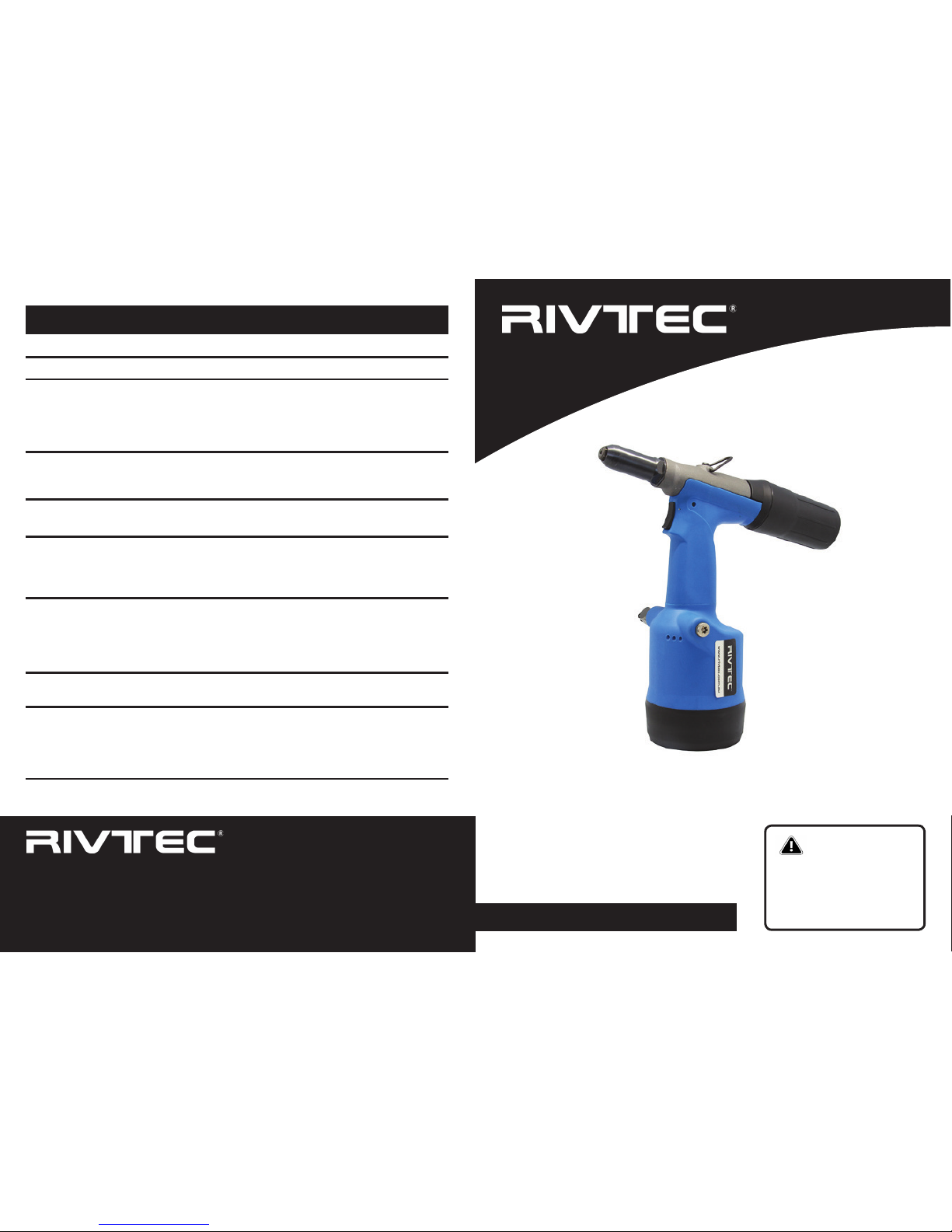
RT-C2
Air Hydraulic Rivet Tool
OPERATOR’S MANUAL
IMPORTANT
Read this Operator’s Manual
carefully before operation.
Keep this manual for future
reference.
TROUBLE SHOOTING
Tool not operating Tool not connected to air supply
Air pressure is insufcient or too
high
Hydraulic oil level is low
Connect to an air supply.
Adjust air supply pressure to
recommended level.
Fill hydraulic oil (Refer to the
“Hydraulic Oil Filling” section).
Indication Cause Solution
Tool not returning Swarf jammed in jaw assembly Clean and lubricate the jaw
assembly (Refer to the “Front
End Service” section).
Tool losing stroke Hydraulic oil level is low Fill hydraulic oil (Refer to the
“Hydraulic Oil Filling” section).
Jaws slipping on
mandrels
Jaws dirty
Jaws worn
Clean and lubricate jaws (Refer
to the “Front End Service”
section).
Replace jaws.
Jaws fail to open Dirty outer sleeving, jaw case or
jaws
Jaw assembly loose
Internally clean the outer sleev-
ing and the jaw assembly (Re-
fer to the “Front End Service”
section).
Tighten the jaw assembly.
Rivet can not be in-
serted into nosepiece
Incorrect nosepiece Install correct nosepiece (size
is marked on nosepiece hex).
Rivet mandrel does
not break
Rivet not fully set
Insufcient air pressure
Hydraulic oil level is low
Repeat stroke, or change rivet
Adjust air supply pressure to
recommended level.
Fill hydraulic oil (Refer to the
“Hydraulic Oil Filling” section).

INTRODUCTION
Rivtec®RT-C2 Air Hydraulic Rivet Tool is a high performance economical air hydraulic rivet tool.
It utilises a lightweight ergonomic design and installs rivets from Ø3.2mm to Ø6.4mm (steel).
SPECIFICATIONS
Weight .............................................. 1.15kg
Pulling Force .......................................10KN
Air Pressure .................................... 5-7 bar
Stroke ................................................18mm
PACKAGE ACCESSORIES
■RT-C2 Rivet Tool
■Operator’s Manual
■Nosepiece for 3.2mm rivets
■Nosepiece for 4.0mm rivets
■Nosepiece for 4.8mm rivets
■Nosepiece for 6.4mm rivets
■Spare Jaw Case
■Spare Jaws (set of 3)
■Spare Jaw Spreader & Spring
■Syringe
■3mm Hex. Key
TOOL DIMENSIONS
124 mm
Ø 102 mm
292 mm
Ø 23 mm
64 mm 285 mm
Ø 54 mm
2
SAFETY INSTRUCTIONS
Caution! To ensure proper functioning and safe operation, read this Operator’s
Manual carefully before operating the RIVTEC® RT-C2 tool
■The rivet tool should be used exclusively to set blind rivets.
■DO NOT overload the tool – work within the prescribed work capacity
■ALWAYS wear eye protection when working with the tool. Personal protection such as
clothes, gloves, safety helmet, non-slipping shoes, ear protectors and protection against
fall are highly recommended.
■This tool is NOT designed for use in explosive atmospheres.
■DO NOT use the tool as a hammer.
■Ensure the tool is not damaged before connecting to the air supply.
■Repair work must be carried out by trained personnel. In case of doubt, ALWAYS send
back the tool to the supplier.
■ALWAYS disconnect the air supply when adjusting, servicing or removing any part of the
tool.
■Keep ngers off the trigger when connecting the air supply or if the air supply fails.
■Keep ngers away from the front of the tool when connecting the air supply or setting
rivets.
■DO NOT point the tool at anyone.
■DO NOT operate tool with the nose housing removed.
■DO NOT operate tool without the mandrel collector.
■DO NOT modify the tool in any way. Modication could damage the tool.
■The operating pressure must not exceed 7 bar.
■DO NOT direct tool exhaust towards anyone.
■Wash hands if exposed to hydraulic uid or lubricant.
■Keep hair, ngers and loose clothing away from moving parts of the tool.
3

BASIC TOOL OPERATION
1. Inspect tool for damage or oil leaking – do not use tool if it is damaged or leaking oil.
2. Ensure correct nosepiece is installed and tightened with a 12mm spanner. (The size of
the nosepiece is marked on the edge of the nosepiece)
3. Ensure the outer sleeving (3) is tightened, by using a 24mm spanner.
4. Connect tool to an air supply.
5. Ensure the mandrel collector (28) is installed.
6. Insert a correct rivet into nosepiece.
7. Pull trigger to install the rivet.
8. Release trigger – When releasing the trigger the jaw assembly returns to the start
position automatically.
9. Eject the spent mandrel by tilting to the rear into the mandrel collector.
10. When the collector is half full, do not use the tool. Disconnect the air supply, unscrew the
collector and empty it.
HYDRAULIC OIL FILLING
It is important that the tool be properly maintained. If the hydraulic oil level is low, the tool will
not work properly.
Caution! Disconnect the air supply while relling the hydraulic oil. Keep the tool
upright during all operations.
1. Unscrew oil screw (69) from the body by using the 3mm Hex. Key (supplied). Check
whether the o ring (29) remains in the hole.
2. Fill the syringe (supplied) with hydraulic oil.
3. Screw the lled syringe up to the o ring in the hole. Then slowly inject the oil into the
tool. Ensure no air is injected. Adequate oil has been added as soon as resistance is
sensed. The excess oil will ow back when the syringe is release if more oil is added
than necessary.
4. Unscrew and remove the syringe from the body. Check whether the o ring remains in
the hole.
5. Screw the oil screw into the hole with the Hex. Key.
6. Wipe off any excess oil.
FRONT END SERVICE
Nosepiece (1)
Outer Sleeving (3)
Jaws (6)
Jaw Case (5)
Lock Ring (9)
Jaw Spreader Housing (10)
Set Nut (12)
Head Assembly (15)
Caution! Disconnect the air supply while servicing front end to avoid injury.
1. Remove outer sleeving (3)
Unscrew the outer sleeving with a 24mm spanner and slide the sleeving off the jaw
assembly.
2. Remove jaw case (5) to access jaws and internal parts
Unscrew and remove the jaw case by using a 17mm spanner on jaw case and a
16mm spanner on jaw spreader housing (10). Remove jaws (6), jaw spreader (7),
spring (8) and lock ring (9).
3. Cleaning
Clean jaws, jaw spreader, spring, lock ring and the thread of the jaw case. Apply
lubricant on jaws and the thread area. Replace jaws if worn or damaged.
4. Re-assemble jaws, internal parts and outer sleeving
Place the jaws into the jaw case and slide the jaw spreader, spring and lock ring
into the jaw case. Apply lubricant to the thread of jaw spreader housing. Screw the
jaw case onto the jaw spreader housing by using the 17mm spanner and the 16mm
spanner. Slide the outer sleeving onto the jaw assembly and tighten with the 24mm
spanner.
If the oil level is too low and the tool fails to operate, service is required by a qualied service
person.
Oil Screw (69)
45
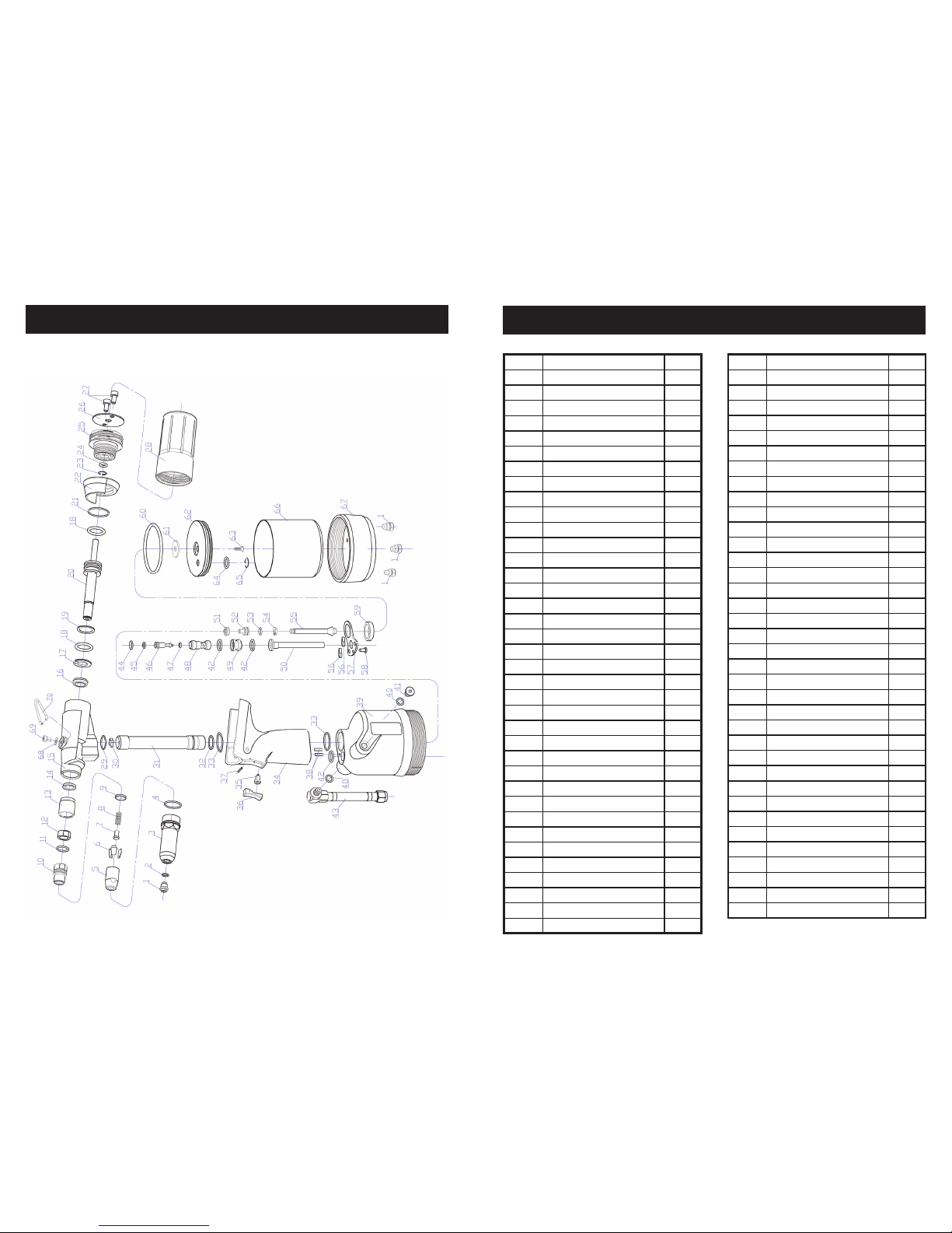
DIAGRAM
6
PARTS LIST
NO. DESCRIPTION QTY.
1NOSEPIECE 3.2MM 1
1NOSEPIECE 4.0MM 1
1NOSEPIECE 4.8MM 1
1NOSEPIECE 6.4MM 1
2O RING 1
3OUTER SLEEVING 1
4O RING 1
5JAW CASE 1
6JAWS 1
7JAW SPREADER 1
8SPRING 1
9LOCK RING 1
10 JAW SPREADER HOUSING 1
11 O RING 1
12 SET NUT 1
13 PLASTIC SEAL SLEEVING 1
14 SEALING RING 1
15 HEAD ASSEMBLY 1
16 LIP SEAL 1
17 SEAL RETAINER 1
18 O RING 2
19 PLASTIC RING 1
20 HEAD PISTON 1
21 O RING 1
22 STEM COLLECTOR ADAPTOR 1
23 CIRCLIP 1
24 O RING 1
25 END CAP 1
26 STEEL PLATE COVER 1
27 BOLT 2
28 MANDREL COLLECTOR 1
29 O RING 1
30 STAR WASHER 1
31 OIL TUBE 1
32 O RING 1
33 O RING 2
34 HANDLE 1
NO. DESCRIPTION QTY.
35 TRIGGER VALVE 1
36 TRIGGER 1
37 TRIGGER PIN 1
38 SPRING PIN 2
39 PLASTIC CYLINDER 1
40 O RING 1
41 SCREW 1
42 O RING 3
43 AIR INLET 1
44 O RING 1
45 O RING 1
46 VALVE CORE 1
47 O RING 1
48 VALVE BODY 1
49 VALVE BASE 1
50 TRANSFER TUBE 1
51 LIP SEAL 1
52 AIR TUBE PISTON 1
53 O RING 1
54 PISTON RING 1
55 PISTON ROD 1
56 SILENCER 2
57 CLAMP PLATE 1
58 TAPPING SCREW 1
59 SET NUT 1
60 O RING 1
61 WASHER 1
62 CYLINDER PISTON 1
63 BOLT 1
64 LIP SEAL 1
65 CIRCLIP 1
66 AIR CYLINDER 1
67 BASE COVER 1
68 WASHER 1
69 OIL SCREW 1
70 HOOK 1
7


