RKI 65-2422RK-05 User manual

www.rkiinstruments.com
65-2422RK-05
Hydrogen Sulfide Transmitter
Operator’s Manual
Part Number: 71-0114RK
Revision: A
Released: 2/16/11

65-2422RK-05 H2S Transmitter
WARNING
Read and understand this instruction manual before operating
detector. Improper use of the detector could result in bodily harm
or death.
Periodic calibration and maintenance of the detector is essential
for proper operation and correct readings. Please calibrate and
maintain this detector regularly! Frequency of calibration
depends upon the type of use you have and the sensor types.
Typical calibration frequencies for most applications are between
3 and 6 months, but can be required more often or less often
based on your usage.

65-2422RK-05 H2S Transmitter
Product Warranty
RKI Instruments, Inc. warrants gas alarm equipment sold by us to be free from defects in
materials, workmanship, and performance for a period of one year from date of shipment
from RKI Instruments, Inc. Any parts found defective within that period will be repaired
or replaced, at our option, free of charge. This warranty does not apply to those items
which by their nature are subject to deterioration or consumption in normal service, and
which must be cleaned, repaired, or replaced on a routine basis. Examples of such items
are:
Warranty is voided by abuse including mechanical damage, alteration, rough handling, or
repair procedures not in accordance with the operator’s manual. This warranty indicates
the full extent of our liability, and we are not responsible for removal or replacement costs,
local repair costs, transportation costs, or contingent expenses incurred without our prior
approval.
THIS WARRANTY IS EXPRESSLY IN LIEU OF ANY AND ALL OTHER
WARRANTIES AND REPRESENTATIONS, EXPRESSED OR IMPLIED,
AND ALL OTHER OBLIGATIONS OR LIABILITIES ON THE PART OF
RKI INSTRUMENTS, INC. INCLUDING BUT NOT LIMITED TO, THE
WARRANTY OF MERCHANTABILITY OR FITNESS FOR A
PARTICULAR PURPOSE. IN NO EVENT SHALL RKI INSTRUMENTS,
INC. BE LIABLE FOR INDIRECT, INCIDENTAL, OR CONSEQUENTIAL
LOSS OR DAMAGE OF ANY KIND CONNECTED WITH THE USE OF
ITS PRODUCTS OR FAILURE OF ITS PRODUCTS TO FUNCTION OR
OPERATE PROPERLY.
This warranty covers instruments and parts sold to users by authorized distributors,
dealers, and representatives as appointed by RKI Instruments, Inc.
We do not assume indemnification for any accident or damage caused by the operation of
this gas monitor, and our warranty is limited to the replacement of parts or our complete
goods.
a) Absorbent cartridges d) Batteries
b) Pump diaphragms and valves e) Filter elements
c) Fuses

65-2422RK-05 H2S Transmitter
Table of Contents
Overview . . . . . . . . . . . . . . . . . . . . . . . . . . . . . . . . . . . . . . . . . . . . . . . . . . . . . . . . . . . . . . . . . . . 1
Specifications. . . . . . . . . . . . . . . . . . . . . . . . . . . . . . . . . . . . . . . . . . . . . . . . . . . . . . . . . . . . . . . . 1
Description. . . . . . . . . . . . . . . . . . . . . . . . . . . . . . . . . . . . . . . . . . . . . . . . . . . . . . . . . . . . . . . . . . 2
H2S Detector . . . . . . . . . . . . . . . . . . . . . . . . . . . . . . . . . . . . . . . . . . . . . . . . . . . . . . . . . . . . . . . . . . . . . . . . . 2
Amplifier . . . . . . . . . . . . . . . . . . . . . . . . . . . . . . . . . . . . . . . . . . . . . . . . . . . . . . . . . . . . . . . . . . . . . . . . . . . . 3
Junction Box. . . . . . . . . . . . . . . . . . . . . . . . . . . . . . . . . . . . . . . . . . . . . . . . . . . . . . . . . . . . . . . . . . . . . . . . . . 4
Installation . . . . . . . . . . . . . . . . . . . . . . . . . . . . . . . . . . . . . . . . . . . . . . . . . . . . . . . . . . . . . . . . . . 4
Mounting the H2S Transmitter . . . . . . . . . . . . . . . . . . . . . . . . . . . . . . . . . . . . . . . . . . . . . . . . . . . . . . . . . . 4
Wiring the H2S Transmitter to a Controller . . . . . . . . . . . . . . . . . . . . . . . . . . . . . . . . . . . . . . . . . . . . . . . 5
Startup. . . . . . . . . . . . . . . . . . . . . . . . . . . . . . . . . . . . . . . . . . . . . . . . . . . . . . . . . . . . . . . . . . . . . . 7
Introducing Incoming Power . . . . . . . . . . . . . . . . . . . . . . . . . . . . . . . . . . . . . . . . . . . . . . . . . . . . . . . . . . . 7
Setting the Zero Signal. . . . . . . . . . . . . . . . . . . . . . . . . . . . . . . . . . . . . . . . . . . . . . . . . . . . . . . . . . . . . . . . . 7
Maintenance. . . . . . . . . . . . . . . . . . . . . . . . . . . . . . . . . . . . . . . . . . . . . . . . . . . . . . . . . . . . . . . . . 8
Preventive Maintenance . . . . . . . . . . . . . . . . . . . . . . . . . . . . . . . . . . . . . . . . . . . . . . . . . . . . . . . . . . . . . . . 8
Troubleshooting . . . . . . . . . . . . . . . . . . . . . . . . . . . . . . . . . . . . . . . . . . . . . . . . . . . . . . . . . . . . . . . . . . . . . . 9
Replacing Components of the H2S Transmitter . . . . . . . . . . . . . . . . . . . . . . . . . . . . . . . . . . . . . . . . . . . 10
Calibration Frequency . . . . . . . . . . . . . . . . . . . . . . . . . . . . . . . . . . . . . . . . . . . . . . . . . . . . . . . 13
Calibration . . . . . . . . . . . . . . . . . . . . . . . . . . . . . . . . . . . . . . . . . . . . . . . . . . . . . . . . . . . . . . . . . 13
Preparing for Calibration. . . . . . . . . . . . . . . . . . . . . . . . . . . . . . . . . . . . . . . . . . . . . . . . . . . . . . . . . . . . . . 13
Setting the Zero Reading . . . . . . . . . . . . . . . . . . . . . . . . . . . . . . . . . . . . . . . . . . . . . . . . . . . . . . . . . . . . . . 14
Setting the Response Reading. . . . . . . . . . . . . . . . . . . . . . . . . . . . . . . . . . . . . . . . . . . . . . . . . . . . . . . . . . 14
Returning to Normal Operation. . . . . . . . . . . . . . . . . . . . . . . . . . . . . . . . . . . . . . . . . . . . . . . . . . . . . . . . 14
Parts List . . . . . . . . . . . . . . . . . . . . . . . . . . . . . . . . . . . . . . . . . . . . . . . . . . . . . . . . . . . . . . . . . . . 15

65-2422RK-05 H2S Transmitter • 1
Overview
This manual describes the hydrogen sulfide (H2S) transmitter. This manual also describes
how to install, start up, maintain, and calibrate the transmitter. A parts list at the end of
this manual lists replacement parts and accessories for the H2S transmitter.
Specifications
WARNING: Do not use this product in a manner not specified in this instruction
manual.
Table 1 lists specifications for the H2S transmitter.
NOTE: The following symbol on the detector label is a caution to the user to refer to this
documentation for installation and operation instructions:
WARNING: When using the 65-2422RK-05, you must follow the instructions and
warnings in this manual to assure proper and safe operation of the
65-2422RK-05 and to minimize the risk of personal injury. Be sure to
maintain and periodically calibrate the 65-2422RK-05 as described in this
manual.
Table 1: Specifications
Target Gas Hydrogen sulfide (H2S)
Area Classification Explosionproof for Class I, Groups B, C, and D
Temperature Code T6
Installation Category Installation Category 1. Signal level, special equipment or parts of
equipment, telecommunication, electronic, etc., with smaller
transient overvoltages than Installation Category (Overvoltage
Category) II (ref. IEC 664).
Input Voltage 11 VDC - 30 VDC
Sampling Method Diffusion
Signal Output 4 to 20 mA
Detection Range 0 to 100 PPM (parts per million)
Accuracy ± 5% of reading or ± 2 ppm H2S (whichever is greater)
H2S Detector Signal Output 0.3 mA at 0 ppm H2S nominal
2.5 mA at 100 ppm H2S nominal
Response Time 90% in 30 seconds
Operating Temperature -40°F to 104°F (-40°C to 40°C)
!

2 • 65-2422RK-05 H2S Transmitter
Description
This section describes the components of the H2S transmitter. The transmitter consists of
the H2S detector, amplifier, and junction box.
Figure 1: H2S Transmitter Component Location
H2S Detector
The H2S detector includes the detector housing and sensor.
Detector Housing
The detector housing protects the sensing components within the housing. Use the
mounting threads at the top of the housing to screw the H2S detector into the bottom
conduit hub of the junction box. Use the removable cap near the bottom of the housing to
access the sensor for maintenance or replacement. The cap protects the sensor from
damage and includes a flame arrestor which contains any sparks which may occur within
the detector housing. A cap gasket seals the interface between the housing and cap. A
flame arrestor guard is permanently bonded to the cap.
Two wires extend from the top of the detector housing. Use these wires to connect the H2S
detector to the amplifier. The housing includes a four-socket pattern. This socket pattern
accepts the sensor’s four pins to secure the sensor within the detector housing. A pre-
amplifier, located between the sockets and two interconnect wires, conditions the sensor’s
signal before the signal reaches the amplifier.
3/4" NPT Conduit Openin
g
For Wire Entry
TOXIC
ZERO
SPAN
Not
Used
4/20
FB +
24V
POWER/SIG
OXY
WG
SENSOR
TP
-TP
+
TOXIC
RD BK
OXYGEN
Interconnect Terminal
Strip
Test Point (+)
Amplifier
Securing Screw (2X)
Detector
Housing
Detector Housing
Cap
Flame Arrestor
Guard
Hydrogen Sulfide
Detector
Test Point (-)
Factory Set
Potentiometer
Zero
Potentiometer
Span
Potentiometer
Jumper Block
I
nstalled On Toxic
Select Header
D
etector Terminal
Strip

65-2422RK-05 H2S Transmitter • 3
Sensor
The sensor is secured within the sensor housing by the four pins. Through a series of
chemical and electrical reactions, the sensor produces an electrical output that is
proportional to the detector range of the transmitter.
Amplifier
The amplifier converts the electrical output from the sensor to a 4 to 20 mA signal (that is
proportional to the detection range) and transmits the signal to a gas monitoring
controller. The amplifier includes the amplifier type selector, detector terminal strip,
interconnect terminal strip, span pot, zero pot, and test points (see Figure 1).
Amplifier Type Selector
The amplifier type selector is near the bottom left corner of the amplifier. It is to the left of
the detector terminal strip and below the span potentiometer.
The amplifier included with the H2S transmitter is designed for use with RKI’s toxic gas
and oxygen transmitters. The amplifier type selector determines for which transmitter the
amplifier is intended. For H2S transmitters, a jumper block is installed over the TOXIC
selector (see Figure 1).
Detector Terminal Strip
The detector terminal strip is the four-point terminal strip near the bottom of the
amplifier. Use the detector terminal strip to connect the H2S detector to the amplifier.
NOTE: The H2S detector is factory-wired to the amplifier. See the Installation section of
this manual for all wiring procedures related to the transmitter.
Interconnect Terminal Strip
The interconnect terminal strip is the four-point terminal strip near the top of the
amplifier. Use the interconnect terminal strip to connect the amplifier to a controller.
Span Pot
The span pot is on the left side of the amplifier. Of the three potentiometers, the span pot
is bottom most. Use the span pot to adjust the transmitter’s response output during the
calibration procedure.
Zero Pot
The zero pot is above the span pot. Use the zero pot to adjust the transmitter’s target gas-
free output during the start-up and calibration procedures.
CAUTION: The third potentiometer is factory-set. Do not adjust it.
Test Points
The test points (labeled TP- and TP+) are on the left and right side of the interconnect
terminal strip. The test points produce a 100 to 500 mV output that is proportional to the
transmitter’s 4 to 20 mA output. Use the test points and a voltmeter to measure the
transmitter’s output during the start-up and calibration procedures.

4 • 65-2422RK-05 H2S Transmitter
Junction Box
Use the junction box to install the H2S transmitter at a mounting site that is remote from
the controller. The junction box also protects the amplifier and wiring connections made
to the amplifier. Use the two 3/4 in. conduit hubs to mount the detector to the junction
box (bottom hub) and connect wiring from the amplifier to the controller (top hub).
NOTE: The H2S detector and amplifier are factory-mounted to the junction box.
Use the junction box’s two mounting holes to mount the H2S transmitter to a vertical
surface at the monitoring site. Use the cover on the front of the junction box to access the
interior of the junction box.
Installation
This section describes procedures to mount the H2S transmitter in the monitoring
environment and wire the transmitter to a controller.
Mounting the H2S Transmitter
1. Select a mounting site that is representative of the monitoring environment. Consider
the following when you select the mounting site.
• Select a site where the transmitter is not likely to be bumped or disturbed. Make
sure there is sufficient room to perform start-up, maintenance, and calibration
procedures.
• Select a site where the target gas is likely to be found first.
NOTE: If your application does not require a specific mounting site, mount the
transmitter at approximately breathing level.
Figure 2: Mounting the H2S Transmitter
3.94
6.10
1
.10
.25 Dia. Mountin
g
Hole, 2X
3/4 NPT
Conduit Hub
8.5 max
2.75
5.20
1 1/2-20 For
Calibration Cup
3.2
max
5.46

65-2422RK-05 H2S Transmitter • 5
If the H2S detector is mounted to the junction box, skip to step 5. If not, continue with
step 2.
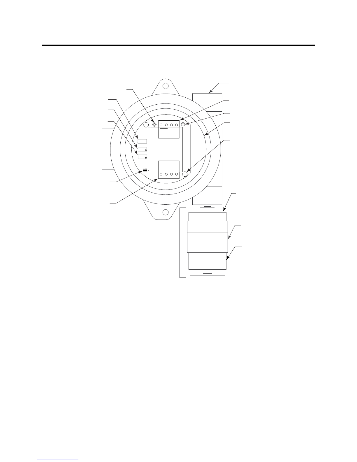
NOTE: The H2S detector is normally provided with a Killark HKB junction box and an
HFC lid rated explosion proof for Class I, Groups B, C, and D. This combination
is shown in Figure 2 above. Any junction box with an internal volume less than
or equal to 69 cubic inches and rated explosion proof for ClassI, Groups B, C, and
D may be used.
2. Remove the junction box cover.
3. Guide the two wires that extend from the top of the H2S detector through the bottom
conduit hub of the junction box.
4. Screw the H2S detector into the bottom conduit hub of the junction box.
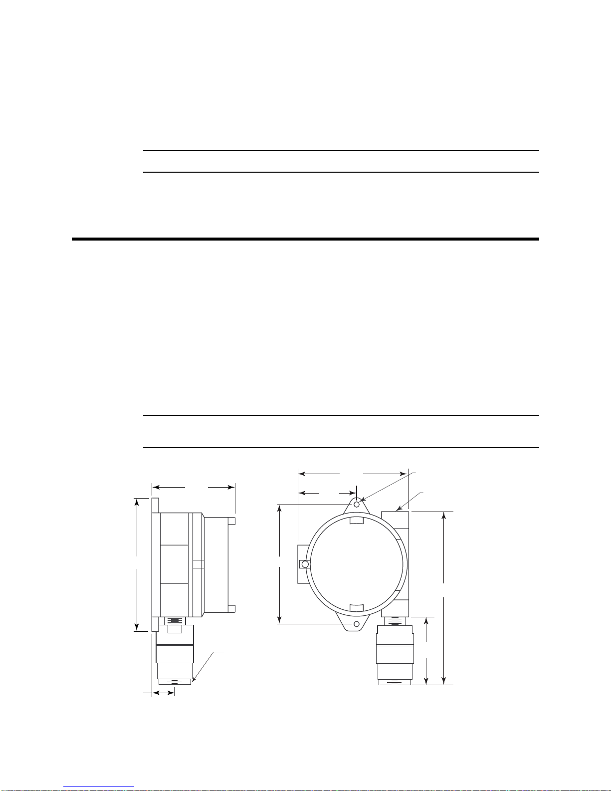
5. At the monitoring site, use #10 screws through the junction box’s two mounting holes
to secure the junction box to a vertical surface.
CAUTION: Mount the H2S transmitter with the detector facing down (see Figure 2).
Wiring the H2S Transmitter to a Controller
WARNING: Always verify that the power source is OFF before you make wiring
connections.
1. Turn off the controller.
2. Turn off or unplug incoming power at the controller.
3. Remove the junction box cover.
4. Verify that the detector leads are wired to the amplifier’s detector terminal strip.
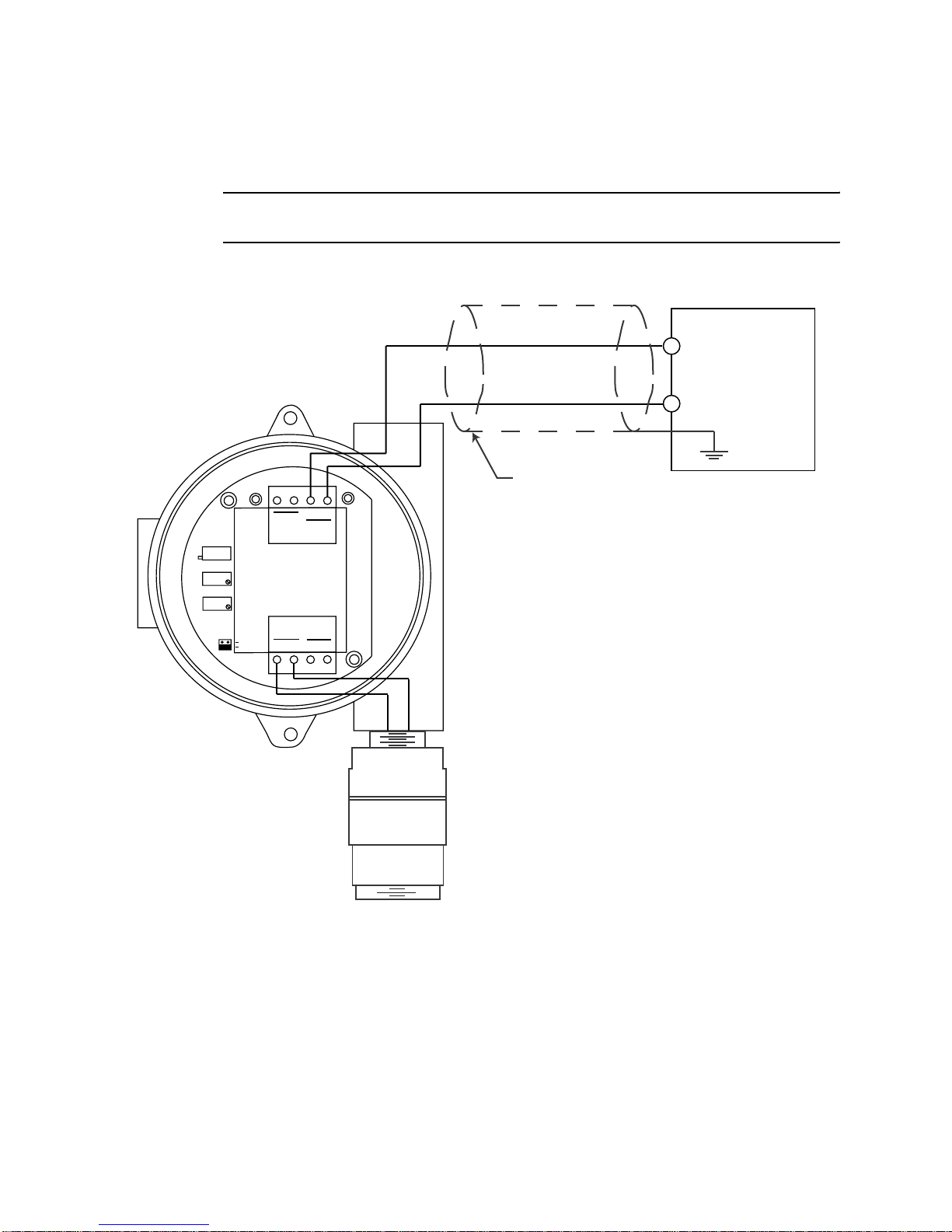
If necessary, connect the detector leads to the detector terminal strip as shown in
Figure 3.
5. Verify that the jumper block is installed over the TOXIC selector of the amplifier type
selector as shown in Figure 3.
6. Guide a two-conductor, shielded cable or two wires in conduit through the top
conduit hub of the junction box.
WARNING: To maintain the explosion proof classification of the H2S detector/junction
box combination, a conduit seal must be used within 18 inches of the
junction box conduit hub used for wiring to the controller.
7. Connect the two wires to the interconnect terminal strip as follows (see Figure 3).
• Connect the positive wire to the terminal labeled 24V +.
• Connect the feedback wire to the terminal labeled 4/20 FB.
CAUTION: If using shielded cable, leave the drain wire insulated and disconnected at the
transmitter. You will connect the opposite end of the cable’s drain wire at the
controller.

6 • 65-2422RK-05 H2S Transmitter
8. Secure the junction box cover to the junction box.
9. Route the cable or wires leading from the H2S transmitter through one of the conduit
hubs at the controller housing.
CAUTION: Do not route power and transmitter wiring through the same conduit hub. The
power cable may disrupt the transmission of the transmitter signal to the controller.
10. Connect the wires to the to the applicable controller transmitter terminal strip as
shown in Figure 3.
Figure 3: Wiring the H2S Transmitter to a Controller
11. If shielded cable is used, connect the cable’s drain wire to an available chassis (earth)
ground at the controller. RKI controllers typically have a ground stud that can be used
to ground the cable’s drain wire.
TOXIC
ZERO
SPAN
4/20
FB
+
24V
POWER/SIG
OXY
WG
SENSOR
TP
-
TP
+
Red
Black
TOXIC
RD BK
OXYGEN
Not
Used
Controller Transmitt
er
Terminals,Typical
+ 24 VDC
4 - 20 mA In
(FB or S)
Cable Shield

65-2422RK-05 H2S Transmitter • 7
Start Up This section describes procedures to start up the H2S transmitter and place the transmitter
into normal operation.
Introducing Incoming Power
1. Complete the installation procedures described earlier in this manual.
2. Verify that the power wiring to the controller is correct and secure. Refer to the
controller instruction manual.
3. Turn on or plug in the incoming power at the power source end, then turn on the
controller.
4. Verify that the controller is on and operating properly. Refer to the controller
instruction manual.
CAUTION: Allow the transmitter to warm up for 5 minutes before you continue with the next
section, “Setting the Zero Signal”.
Setting the Zero Signal
WARNING: Do not remove the sensor cap or junction box cover while the circuits are
energized unless the area is determined to be non-hazardous. Keep the
sensor cap and junction box cover tightly closed during operation.
NOTE: If you can verify that the detector is in a fresh air environment (environment
known to be of normal oxygen content and free of toxic and combustible gases),
it is not necessary to apply zero air when verifying or setting the fresh air
reading.
The procedure below describes applying zero emission air, usually called zero air, using a
calibration kit that includes a calibration cup, calibration gas, sample tubing, and a fixed
flow regulator with an on/off knob. RKI Instruments, Inc. recommends using a 0.5 LPM
(liters per minute) fixed flow regulator.
1. Unscrew and remove the junction box cover from the junction box.
2. Set a voltmeter to measure in the millivolt (mV) range.
3. Plug the voltmeter leads into the test points on the amplifier. Plug the positive lead
into the test point labeled TP+; plug the negative lead into the test point labeled TP-.
4. Screw the calibration cup onto the bottom of the detector.
5. Screw the regulator into the zero air calibration cylinder.
6. Use the sample tubing to connect the regulator to the calibration cup.
7. Turn the regulator’s on/off knob counterclockwise to open it. Gas will begin to flow.
8. Allow the gas to flow for 2 minutes.
9. Verify a voltmeter reading of 100 mV (±2 mV).
10. If necessary, use a flat-blade screwdriver to adjust the span pot until the voltmeter
reading is 100 mV (±2 mV).
11. Turn the regulator’s on/off knob clockwise to close it.

8 • 65-2422RK-05 H2S Transmitter
12. Unscrew the calibration cup from the detector.
13. Unscrew the regulator from the zero air calibration cylinder. For convenience, leave
the sample tubing connected to the regulator and the calibration cup.
14. Store the components of the calibration kit in a safe and convenient place.
15. Remove the voltmeter leads from the test points.
16. Secure the junction box cover to the junction box.
Maintenance
This section describes maintenance procedures. It includes preventive maintenance,
troubleshooting, and component replacement procedures.
Preventive Maintenance
This section describes a preventive maintenance schedule to ensure the optimum
performance of the H2S transmitter. It includes daily, monthly, and quarterly procedures.
Daily
Verify a display reading of 0 PPM H2S at the controller. Investigate significant changes in
the display reading.
Monthly
This procedure describes a test to verify that the H2S transmitter responds properly to
hydrogen sulfide. It describes the test using a calibration kit that includes a calibration
cup, calibration gas, sample tubing, and a fixed flow regulator with an on/off knob. RKI
Instruments, Inc. recommends using a 0.5 LPM (liters per minute) fixed flow regulator.
NOTE: Performing a response test on the H2S transmitter may cause alarms. Be sure to
put the controller into its calibration program or disable external alarms before
performing this test.
Preparing for the response test
1. Place the controller into its calibration program or disable external alarms.
2. Verify that the controller display reading for the channel you are testing is 0.
If the display reading is not zero, set the zero reading of the transmitter as described
in the Start Up section of this manual, then continue this procedure.
3. Screw the calibration cup onto the bottom of the H2S detector.
4. Screw the regulator into the calibration cylinder.
5. Use the sample tubing to connect the regulator to the calibration cup.
6. Set a voltmeter to measure in the millivolt (mV) range.
WARNING: Do not remove the sensor cap or junction box cover while the circuits are
energized unless the area is determined to be non-hazardous. Keep the
sensor cap and junction box cover tightly closed during operation.
7. Remove the junction box cover, then plug the voltmeter leads into the test points on
the amplifier.

65-2422RK-05 H2S Transmitter • 9
Plug the positive lead into the test point labeled TP+; plug the negative lead into the
test point labeled TP-.
8. Use the following formula to determine the correct test points output for the test
sample.
Output (mV) = (calibrating sample/fullscale) X 400 + 100
For example, with a test sample of 25 PPM H2S and a fullscale setting of
100 PPM, the correct output is 200 mV.
200 (mV) = (25/100) X 400 +100
Performing the response test
1. Turn the regulator on/off knob counterclockwise to open it. The sample will begin to
flow.
2. Allow the gas to flow for two minutes, then verify that the reading is within ± 20% of
the response reading you determined earlier.
NOTE: If the readings are not within ± 20% of the correct response reading, calibrate the
affected transmitter(s) as described in the Calibration section of this manual.
3. Turn the regulator on/off knob clockwise to close it.
4. Unscrew the regulator from the calibration cylinder.
5. Unscrew the calibration cup from the H2S detector.
6. Remove the voltmeter leads from the amplifier test points.
7. Reinstall the junction box cover.
8. When the controller display reading falls below the alarm setpoints, return the
controller to normal operation.
Quarterly
Calibrate the H2S transmitter as described in the Calibration section of this manual.
Troubleshooting
The troubleshooting guide describes symptoms, probable causes, and recommended
action for problems you may encounter with the H2S transmitter.
NOTE: This troubleshooting guide describes transmitter problems only. See the
controller instruction manual for problems you may encounter with the
controller.
Fail Condition
Symptoms
• The controller indicates a fail condition.
Probable causes
• The transmitter wiring is disconnected or misconnected.
• The transmitter’s zero reading is low enough to cause a fail condition.
• The transmitter is malfunctioning.

10 • 65-2422RK-05 H2S Transmitter
Recommended action
• Verify that the transmitter wiring is correct and secure.
• Calibrate the transmitter.
• If the fail condition continues, replace the H2S sensor.
• If the fail condition continues, contact RKI for further instruction.
Slow or No Response/Difficult or Unable to Calibrate
Symptoms
• The transmitter responds slowly or does not respond during the monthly response
test.
• Unable to accurately set the zero or response reading during the calibration
procedure.
• The transmitter requires frequent calibration.
NOTE: Under “normal” circumstances, the transmitter requires calibration once every
three months. Some applications may require a more frequent calibration
schedule.
Probable causes
• The calibration cylinder is low, out-dated, or defective.
• The transmitter is malfunctioning.
Recommended action
1. Verify that the calibration cylinder contains an adequate supply of a fresh test sample.
2. If the calibration/response difficulties continue, replace the H2S sensor as described
later in this section.
3. If the calibration/response difficulties continue, contact RKI Instruments, Inc. for
further instruction.
Replacing Components of the H2S Transmitter
This section includes procedure to replace the H2S sensor and amplifier. A procedure to
replace the entire detector assembly is at the end of this section. In most cases, it is not
necessary to replace the entire detector assembly.
Replacing the Sensor
CAUTION: The sensor contains electrolyte which is a dilute acid. Do not disassemble the sensor
when replacing it with a new one. If sensor electrolyte comes in contact with your
skin, wash affected area thoroughly with soap and water.
1. Turn off the controller.
2. Turn off or unplug incoming power at the controller.
3. Unscrew the bottom section of the H2S detector housing from the top section.
4. Unplug and remove the H2S sensor.
5. Carefully plug the replacement sensor into the socket pattern that is located in the top
section of the detector housing.

65-2422RK-05 H2S Transmitter • 11
NOTE: Match the sensor’s male pins with the four female sockets as you plug the sensor
into the socket.
6. Screw the bottom section of the detector housing onto the top section.
7. Turn on or plug in incoming power at the power source end.
8. Turn on the controller.
CAUTION: Allow the replacement sensor to warm up for 5 minutes before you continue with the
next step.
9. Calibrate the replacement sensor as described in the Calibration section of this
manual.
Replacing the Amplifier
1. Turn off the controller.
2. Turn off or unplug incoming power at the power source end.
3. Remove the junction box cover.
4. Disconnect the detector leads from the detector terminal strip.
5. Unscrew and remove the two screws that secure the amplifier to the junction box.
The screws are at the top left and bottom right of the amplifier.
6. Remove the amplifier.
7. Place the new amplifier in the same position as the old amplifier.
8. Use the two screws you removed in step 5 to secure the new amplifier to the junction
box.
9. Verify that the jumper block is installed over the TOXIC selector of the amplifier type
selector as shown in Figure 3.
10. Reconnect the wiring from the controller to the interconnect terminal strip as shown
in Table 2 and Figure 3.
11. Reconnect the detector leads to the detector terminal strip as shown in Table 3 and
Figure 3.
Table 2: Reconnecting the H2S Amplifier to a Controller
Amplifier
Interconnect Terminal Strip Controller Transmitter
Terminal Strip (typical)
4/20 FB 4 -20 (FB)
24V + + V (11 - 30 VDC)
Table 3: Reconnecting the H2S Detector to the Amplifier
H2S Detector Lead Amplifier
Interconnect Terminal Strip
Black TOXIC BK

12 • 65-2422RK-05 H2S Transmitter
12. Reinstall the junction box cover.
13. Turn on or plug in incoming power at the power source end.
14. Turn on the controller.
CAUTION: Allow the sensor to warm up for 5 minutes before you continue with the next step.
15. Calibrate the H2S transmitter as described in the Calibration section of this manual.
Replacing the H2S Detector
NOTE: In most cases, it is only necessary to replace the H2S sensor.
1. Turn off the controller.
2. Turn off or unplug incoming power at the power source end.
3. Remove the junction box cover.
4. Disconnect the detector leads from the detector terminal strip. Note the position of the
color-coded leads as you remove them.
5. Unscrew the detector from the junction box.
6. Guide the detector leads of the replacement detector through the bottom conduit hub
of the junction box, then screw the mounting threads of the detector into the conduit
hub.
7. Connect the detector leads to the detector terminal strip as shown in Table 4 and
Figure 3.
8. Reinstall the junction box cover.
9. Turn on or plug in incoming power at the controller.
10. Turn on the controller.
CAUTION: Allow the replacement detector to warm up for 5 minutes before you continue with
the next step.
11. Calibrate the replacement detector as described in the Calibration section of this
Red TOXIC RD
Table 4: Connecting the Replacement H2S Detector to the Amplifier
H2S Detector Lead Amplifier
Interconnect Terminal Strip
Black TOXIC BK
Red TOXIC RD
Table 3: Reconnecting the H2S Detector to the Amplifier
H2S Detector Lead Amplifier
Interconnect Terminal Strip

65-2422RK-05 H2S Transmitter • 13
manual.
12. Secure the junction box cover to the junction box.
Calibration Frequency
Although there is no particular calibration frequency that is correct for all applications, a
calibration frequency of every 3 months is adequate for most H2S transmitter applications.
Unless experience in a particular application dictates otherwise, RKI Instruments, Inc.
recommends a calibration frequency of every 3 months for the H2S transmitter.
If an application is not very demanding, for example detection in a clean, temperature
controlled environment, and calibration adjustments are minimal at calibration, then a
calibration frequency of every 6 months is adequate.
If an application is very demanding, for example if the environment is not well controlled,
then more frequent calibration than every 3 months may be necessary.
Calibration
This section describes how to calibrate the H2S transmitter. It includes procedures to
prepare for calibration, set the zero reading, set the response reading, and return to
normal operation. It describes the test using a calibration kit that includes a calibration
cup, calibration gas, sample tubing, and a fixed flow regulator with an on/off knob. RKI
Instruments, Inc. recommends using a 0.5 LPM (liters per minute) fixed flow regulator.
Preparing for Calibration
NOTE: Calibrating the H2S transmitter may cause alarms. Be sure to put the controller
into its calibration program or disable external alarms before calibration.
1. Screw the calibration cup onto the bottom of the H2S detector.
2. Screw the regulator into the zero air calibration cylinder.
3. Use the sample tubing to connect the fixed flow regulator to the calibration cup.
4. Set a voltmeter to measure in the millivolt (mV) range.
WARNING: Do not remove the sensor cap or junction box cover while the circuits are
energized unless the area is determined to be non-hazardous. Keep the
sensor cap and junction box cover tightly closed during operation.
5. Remove the junction box cover, then plug the voltmeter leads into the test points on
the amplifier.
Plug the positive lead into the test point labeled TP+; plug the negative lead into the
test point labeled TP-.
6. Use the following formula to determine the correct test points output for the
calibrating sample.
Output (mV) = (calibrating sample/fullscale) X 400 + 100
For example, with a calibrating sample of 25 PPM H2S and a fullscale setting of
100 PPM, the correct output is 200 mV.
200 (mV) = (25/100) X 400 +100

14 • 65-2422RK-05 H2S Transmitter
Setting the Zero Reading
NOTE If you can verify that the H2S transmitter is in a fresh air environment, you do not
need to apply zero air to the detector before adjusting the zero reading.
1. Turn the regulator on/off knob counterclockwise to open it. Gas will automatically
begin to flow.
2. Allow the gas to flow for two minutes.
3. Verify a reading of 100 mV (± 2mV).
4. If necessary, use the zero pot on the amplifier to adjust the reading to 100 mV (± 2mV).
5. Unscrew the regulator from the zero air calibration cylinder.
Leave the sample tubing connected to the regulator and the calibration cup.
Setting the Response Reading
1. Screw the regulator into the calibration cylinder. Verify that the calibration gas is
representative of the transmitter’s target gas.
2. Turn the regulator on/off knob counterclockwise to open it.
3. Allow the gas to flow for two minutes.
4. Verify that the reading matches the response reading (± 2mV) you determined earlier.
5. If necessary, use the span pot on the amplifier to adjust the reading to match the
correct response reading.
6. Turn the regulator on/off knob clockwise to close it.
7. Unscrew the regulator from the calibration cylinder.
8. Unscrew the calibration cup from the detector.
NOTE: For convenience, leave the components of the calibration kit connected by the
sample tubing.
Returning to Normal Operation
1. Remove the voltmeter leads from the amplifier test points.
2. Secure the junction box cover to the junction box.
3. When the display reading falls below the alarm setpoints, return the controller to
normal operation.
4. Verify that the controller display reading decreases and stabilizes at 0 ppm.
5. Store the components of the calibration kit in a safe and convenient place.

65-2422RK-05 H2S Transmitter • 15
Parts List
Table 5 lists replacement parts and accessories for the H2S transmitter.
Table 5: Parts List
Part Number Description
06-1248RK Sample tubing (order by the foot)
07-0033RK Detector housing cap gasket
18-0405RK-01 Junction box (without cover; pre drilled for amplifier)
18-0406RK Junction box cover
57-1060RK Amplifier (specify target gas when ordering)
65-2422RK-05 H2S transmitter (includes detector and amplifier), CSA classified
65-2423RK-05 H2S replacement detector assembly (includes sensor), CSA classified
71-0113RK 65-2422RK-05 H2S Transmitter Operator’s Manual (this document)
81-0151RK-04 Calibration cylinder (25 PPM H2S in nitrogen; 34 liter aluminum)
81-0076RK-01 Zero air calibration cylinder (34 liter steel)
81-1050RK Regulator with gauge and knob, 0.5 LPM, for 17 liter and 34 liter steel cali-
bration cylinders
81-1051RK Regulator with gauge and knob, 0.5 LPM, for 34 liter aluminum calibration
cylinders and 58 liter and 103 liter steel calibration cylinders
81-1117RK Calibration cup
ES-1537-H2S H2S replacement sensor
Table of contents
Other RKI Transmitter manuals
Popular Transmitter manuals by other brands

Becker
Becker Centronic TimeControl TC4410-II Assembly and operating instructions

Intermatic
Intermatic RC939 Installation, operation & service manual

Sony
Sony DCC-FMT3 operating instructions

Evikon
Evikon PluraSens E2608-Cl2 user manual

GE
GE 99001 user manual

Movie Vision
Movie Vision MV-TX1 Installation and operation manual

Emerson
Emerson Rosemount 3051G quick start guide

Harris
Harris Ranger Series Commissioning manual

Becker
Becker Centronic / B-Tronic EasyControl MC611 Assembly and operating instructions

Intellinet
Intellinet 561211 Quick instruction guide

Abus
Abus FUAT50000 manual

Hall Technologies
Hall Technologies DSCV1-70-TX user manual