RLE Technologies SeaHawk LD5200 User manual

Leak Detection
User Guide
LD5200
Version 2.6
Firmware Version 2.2.15

2 LD5200 User Guide 800.518.1519
Copyright and Trademark Notices
© Raymond & Lae Engineering, Inc. 2012. All rights reserved. RLE® is a registered trademark and
SeaHawk™, Falcon™, and Raptor™ are trademarks of Raymond & Lae Engineering, Inc. The
products sold by Raymond & Lae Engineering, Inc. are subject to the limited warranty, limited liability,
and other terms and conditions of sale set forth at http://www.rletech.com/.
Revision History
Rev. No. Date
1.0 April 2011
2.0 April 2012
2.1 May 2012
2.2 July 2013
2.3 April 2014
2.4 September 2015
2.5 November 2016
2.6 December 2016

rletech.com LD5200 User Guide 3
Manufacturer’s Notes
This product is manufactured by RLE Technologies, 104 Racquette Drive, Fort Collins, CO, 80524.
If this product is used in any manner other than that specified by the manufacturer, the protection
provided by the equipment may be impaired.
Product Registration
Product registration helps RLE Technologies inform owners of:
• Product upgrades
• Firmware enhancements
• New products and technologies
• Special offers available only to registered users
Any information provided to RLE Technologies through the registration form will be regarded as
confidential. RLE will not sell or distribute any of the information to third parties.
Technical Support
Before you install an LD5200, refer to RLE Technologies’ website, www.rletech.com, to ensure you are
using the most recent version of all documentation.
Personal assistance is available Monday through Friday, from 8:00 a.m. to 5:00 p.m. MST.
The following information is located on the bottom of each LD5200 unit. Please have this information
available whenever a technical support call is placed:
The LD5200 is not a field-serviceable item and must be sent back to RLE Technologies for mechanical
repair. Power must be disconnected (unplugged) from the LD5200 any time the unit is mechanically
serviced. Physically unplug power from the unit any time you are making wiring connections to or from
the LD5200.
RLE cannot accept an item for repair without a Return Materials Authorization number, which must be
provided by RLE.
Product Model Number
Product Serial Number
Product Manufacture Date

4 LD5200 User Guide 800.518.1519
RLE Product Warranty
Seller warrants to the Ultimate Purchaser (the purchaser who buys for use and not for resale) that all
products furnished under this order and which are manufactured by Seller will conform to final
specifications, drawings, samples and other written descriptions approved in writing by Seller, and will be
free from defects in materials and workmanship. These warranties shall remain in effect for RLE
Manufactured parts for a period of twenty four (24) months after shipment. These warranties shall remain in
effect for RLE distributor supplied parts for a period defined by the original manufacturer’s warranty after
shipment. All parts replaced or repaired in the warranty period shall carry the unexpired portion of the
original warranty. A unit placed with the purchaser on consignment and then later purchased will be
warranted for twenty four (24) months [original manufacturer’s warranty for RLE distributor supplied parts]
from the time the Seller receives notification of the Purchaser’s intent to purchase said consigned item.
Products are NOT life and safety certified. In no event shall the Seller be liable for loss, damage, or expense
directly or indirectly arising from the use of the units, or from any other cause, except as expressly stated in
this warranty. Seller makes no warranties, express or implied, including any warranty as to merchantability
or fitness for a particular purpose or use. Seller is not liable for and Purchaser waives any right of action it
has or may have against Seller for any consequential or special damages arising out of any breach of
warranty, and for any damages Purchaser may claim for damage to any property or injury or death to any
person arising out of its purchase or the use, operation, or maintenance of the product. Seller will not be
liable for any labor subcontracted or performed by Purchaser for preparation of warranted item for return to
Seller’s factory or for preparation work for field repair or replacement. Invoicing of Seller for labor either
performed or subcontracted by Purchaser will not be considered as a liability by the Seller.
The liability of Seller hereunder is limited to replacing or repairing at Seller’s factory or on the job site at
Seller’s option, any part or parts which have been returned to the Seller and which are defective or do not
conform to such specifications, drawings or other written descriptions; provided that such part or parts are
returned by the Ultimate Purchaser within ninety (90) days after such defect is discovered. The Seller shall
have the sole right to determine if the parts are to be repaired at the job site or whether they are to be
returned to the factory for repair or replacement. All items returned to Seller for repair or replacement must
be sent freight, prepaid to its factory. Purchaser must obtain Seller’s Return Material Authorization prior to
returning items. The above conditions must be met if warranty is to be valid. Seller will not be liable for any
damage done by unauthorized repair work, unauthorized replacement parts, from any misapplication of the
item, or for damage due to accident, abuse, or act of God.
This warranty shall be exclusive of any and all other warranties express or implied and may be modified only
by writing signed by any officer of the Seller. This warranty shall extend to the Ultimate Purchaser but to no
one else. Accessories supplied by Seller but manufactured by others carry any warranty the manufacturers
have made to Seller and which can be passed on to the Ultimate Purchaser.
Seller makes no warranty with respect to whether the products sold hereunder infringe any patent, U.S. or
foreign, and Purchaser represents that any specially ordered products do not infringe any patent. Purchaser
agrees to indemnify and hold Seller harmless from any liability by virtue of any patent claims where
Purchaser has ordered a product conforming to Purchaser’s specifications, or conforming to Purchaser’s
specific design.
Purchaser has not relied and shall not rely on any oral representation regarding the Product sold hereunder
and any oral representation shall not bind Seller and shall not be part of any warranty.

Contents
rletech.com LD5200 User Guide 5
1 Product Overview . . . . . . . . . . . . . . . . . . . . . . . . . . . . . . . . . . . . . . . . . . . . . . . . . . .13
Description . . . . . . . . . . . . . . . . . . . . . . . . . . . . . . . . . . . . . . . . . . . . . . . . . . . . . . . . . . . . . . . . . . . . . . 13
Operation . . . . . . . . . . . . . . . . . . . . . . . . . . . . . . . . . . . . . . . . . . . . . . . . . . . . . . . . . . . . . . . . . . . . . . . 13
Supervised System . . . . . . . . . . . . . . . . . . . . . . . . . . . . . . . . . . . . . . . . . . . . . . . . . . . . . . . . . . . 13
Distance-Read Leak Detection . . . . . . . . . . . . . . . . . . . . . . . . . . . . . . . . . . . . . . . . . . . . . . . . . . 14
User Configuration and Communication . . . . . . . . . . . . . . . . . . . . . . . . . . . . . . . . . . . . . . . . . . . 14
2 Installation . . . . . . . . . . . . . . . . . . . . . . . . . . . . . . . . . . . . . . . . . . . . . . . . . . . . . . . . .15
Prepare for Installation . . . . . . . . . . . . . . . . . . . . . . . . . . . . . . . . . . . . . . . . . . . . . . . . . . . . . . . . . . . . . 15
Mount the LD5200. . . . . . . . . . . . . . . . . . . . . . . . . . . . . . . . . . . . . . . . . . . . . . . . . . . . . . . . . . . . . . . . . 16
Establish Physical Connections . . . . . . . . . . . . . . . . . . . . . . . . . . . . . . . . . . . . . . . . . . . . . . . . . . . . . . 16
TB1: 4-20mA Output . . . . . . . . . . . . . . . . . . . . . . . . . . . . . . . . . . . . . . . . . . . . . . . . . . . . . . . . . . 18
TB2: Sensing Cable Interface . . . . . . . . . . . . . . . . . . . . . . . . . . . . . . . . . . . . . . . . . . . . . . . . . . . 18
TB3: Maintenance Relay . . . . . . . . . . . . . . . . . . . . . . . . . . . . . . . . . . . . . . . . . . . . . . . . . . . . . . . 18
TB4: Two Fault/Leak Relay Outputs . . . . . . . . . . . . . . . . . . . . . . . . . . . . . . . . . . . . . . . . . . . . . . 18
P1: EIA-232 Connector . . . . . . . . . . . . . . . . . . . . . . . . . . . . . . . . . . . . . . . . . . . . . . . . . . . . . . . . 19
SW1: TB5 Port 3 Termination Switch. . . . . . . . . . . . . . . . . . . . . . . . . . . . . . . . . . . . . . . . . . . . . . 19
TB5 and TB6: EIA-485 Modbus Ports . . . . . . . . . . . . . . . . . . . . . . . . . . . . . . . . . . . . . . . . . . . . . 19
SW2: TB6 Port 2 (Bottom Row) Termination Switch . . . . . . . . . . . . . . . . . . . . . . . . . . . . . . . . . . 20
SW3: TB6 Port 1 (Top Row) Termination Switch. . . . . . . . . . . . . . . . . . . . . . . . . . . . . . . . . . . . . 20
P2: RJ45 Network . . . . . . . . . . . . . . . . . . . . . . . . . . . . . . . . . . . . . . . . . . . . . . . . . . . . . . . . . . . . 20
P3: Optional Power Connection . . . . . . . . . . . . . . . . . . . . . . . . . . . . . . . . . . . . . . . . . . . . . . . . . . 20
TB7: Input Power (from Input AC Power Supply). . . . . . . . . . . . . . . . . . . . . . . . . . . . . . . . . . . . . 20
DS1: Status LED . . . . . . . . . . . . . . . . . . . . . . . . . . . . . . . . . . . . . . . . . . . . . . . . . . . . . . . . . . . . . 20
Connect the SeaHawk Sensing Cable . . . . . . . . . . . . . . . . . . . . . . . . . . . . . . . . . . . . . . . . . . . . . . . . . 21
Connect Lengths of Sensing Cable . . . . . . . . . . . . . . . . . . . . . . . . . . . . . . . . . . . . . . . . . . . . . . . 21
Secure Sensing Cable to the Floor . . . . . . . . . . . . . . . . . . . . . . . . . . . . . . . . . . . . . . . . . . . . . . . 21
Apply Power to the LD5200 . . . . . . . . . . . . . . . . . . . . . . . . . . . . . . . . . . . . . . . . . . . . . . . . . . . . . . . . . 22
Configure Communications. . . . . . . . . . . . . . . . . . . . . . . . . . . . . . . . . . . . . . . . . . . . . . . . . . . . . . . . . . 23
Access the Configuration Menu . . . . . . . . . . . . . . . . . . . . . . . . . . . . . . . . . . . . . . . . . . . . . . . . . . 23
Test the System . . . . . . . . . . . . . . . . . . . . . . . . . . . . . . . . . . . . . . . . . . . . . . . . . . . . . . . . . . . . . . . . . . 24
Calibrate Cable Resistance. . . . . . . . . . . . . . . . . . . . . . . . . . . . . . . . . . . . . . . . . . . . . . . . . . . . . . . . . . 25
Configure Security Settings. . . . . . . . . . . . . . . . . . . . . . . . . . . . . . . . . . . . . . . . . . . . . . . . . . . . . . . . . . 27
General Operation. . . . . . . . . . . . . . . . . . . . . . . . . . . . . . . . . . . . . . . . . . . . . . . . . . . . . . . . . . . . . . . . . 27
3 LCD Touch Screen Interface . . . . . . . . . . . . . . . . . . . . . . . . . . . . . . . . . . . . . . . . . .29
Main Menu . . . . . . . . . . . . . . . . . . . . . . . . . . . . . . . . . . . . . . . . . . . . . . . . . . . . . . . . . . . . . . . . . . . . . . 30
Silence Button . . . . . . . . . . . . . . . . . . . . . . . . . . . . . . . . . . . . . . . . . . . . . . . . . . . . . . . . . . . . . . . . . . . . 30
Alarms Button . . . . . . . . . . . . . . . . . . . . . . . . . . . . . . . . . . . . . . . . . . . . . . . . . . . . . . . . . . . . . . . . . . . . 31
History . . . . . . . . . . . . . . . . . . . . . . . . . . . . . . . . . . . . . . . . . . . . . . . . . . . . . . . . . . . . . . . . . . . . . 32
Status Button. . . . . . . . . . . . . . . . . . . . . . . . . . . . . . . . . . . . . . . . . . . . . . . . . . . . . . . . . . . . . . . . . . . . . 33
System Button . . . . . . . . . . . . . . . . . . . . . . . . . . . . . . . . . . . . . . . . . . . . . . . . . . . . . . . . . . . . . . . 35
Setup Button . . . . . . . . . . . . . . . . . . . . . . . . . . . . . . . . . . . . . . . . . . . . . . . . . . . . . . . . . . . . . . . . . . . . . 36
Leak Settings . . . . . . . . . . . . . . . . . . . . . . . . . . . . . . . . . . . . . . . . . . . . . . . . . . . . . . . . . . . . . . . . 37
Virtual Zone . . . . . . . . . . . . . . . . . . . . . . . . . . . . . . . . . . . . . . . . . . . . . . . . . . . . . . . . . . . . . . . . . 40
Slave Zone . . . . . . . . . . . . . . . . . . . . . . . . . . . . . . . . . . . . . . . . . . . . . . . . . . . . . . . . . . . . . . . . . . 41
4-20mA Output. . . . . . . . . . . . . . . . . . . . . . . . . . . . . . . . . . . . . . . . . . . . . . . . . . . . . . . . . . . . . . . 42

6LD5200 User Guide 800.518.1519
Preventative Maintenance . . . . . . . . . . . . . . . . . . . . . . . . . . . . . . . . . . . . . . . . . . . . . . . . . . . . . . 43
System Settings . . . . . . . . . . . . . . . . . . . . . . . . . . . . . . . . . . . . . . . . . . . . . . . . . . . . . . . . . . . . . . 44
EIA-485 / Modbus / N2 . . . . . . . . . . . . . . . . . . . . . . . . . . . . . . . . . . . . . . . . . . . . . . . . . . . . . . . . . 45
Bacnet . . . . . . . . . . . . . . . . . . . . . . . . . . . . . . . . . . . . . . . . . . . . . . . . . . . . . . . . . . . . . . . . . . . . . 46
Clear History. . . . . . . . . . . . . . . . . . . . . . . . . . . . . . . . . . . . . . . . . . . . . . . . . . . . . . . . . . . . . . . . . 46
4 Web Interface . . . . . . . . . . . . . . . . . . . . . . . . . . . . . . . . . . . . . . . . . . . . . . . . . . . . . . 47
Home Page . . . . . . . . . . . . . . . . . . . . . . . . . . . . . . . . . . . . . . . . . . . . . . . . . . . . . . . . . . . . . . . . . . . . . . 47
Identity . . . . . . . . . . . . . . . . . . . . . . . . . . . . . . . . . . . . . . . . . . . . . . . . . . . . . . . . . . . . . . . . . . . . . . . . . . 48
Configuration . . . . . . . . . . . . . . . . . . . . . . . . . . . . . . . . . . . . . . . . . . . . . . . . . . . . . . . . . . . . . . . . . . . . . 49
Leak . . . . . . . . . . . . . . . . . . . . . . . . . . . . . . . . . . . . . . . . . . . . . . . . . . . . . . . . . . . . . . . . . . . . . . . 50
Virtual Zone . . . . . . . . . . . . . . . . . . . . . . . . . . . . . . . . . . . . . . . . . . . . . . . . . . . . . . . . . . . . . . . . . 55
Slave Controller . . . . . . . . . . . . . . . . . . . . . . . . . . . . . . . . . . . . . . . . . . . . . . . . . . . . . . . . . . . . . . 56
Slave Zones . . . . . . . . . . . . . . . . . . . . . . . . . . . . . . . . . . . . . . . . . . . . . . . . . . . . . . . . . . . . . . . . . 57
Network/IP . . . . . . . . . . . . . . . . . . . . . . . . . . . . . . . . . . . . . . . . . . . . . . . . . . . . . . . . . . . . . . . . . . 58
Network Statistics . . . . . . . . . . . . . . . . . . . . . . . . . . . . . . . . . . . . . . . . . . . . . . . . . . . . . . . . . . . . . 59
Web . . . . . . . . . . . . . . . . . . . . . . . . . . . . . . . . . . . . . . . . . . . . . . . . . . . . . . . . . . . . . . . . . . . . . . . 60
Map. . . . . . . . . . . . . . . . . . . . . . . . . . . . . . . . . . . . . . . . . . . . . . . . . . . . . . . . . . . . . . . . . . . . . . . . 61
Upload the Map Image. . . . . . . . . . . . . . . . . . . . . . . . . . . . . . . . . . . . . . . . . . . . . . . . . . . . . . 64
Map Reference Points . . . . . . . . . . . . . . . . . . . . . . . . . . . . . . . . . . . . . . . . . . . . . . . . . . . . . . 65
Test the Mapped Coordinates . . . . . . . . . . . . . . . . . . . . . . . . . . . . . . . . . . . . . . . . . . . . . . . . 67
Viewing the Map. . . . . . . . . . . . . . . . . . . . . . . . . . . . . . . . . . . . . . . . . . . . . . . . . . . . . . . . . . . 70
Clock. . . . . . . . . . . . . . . . . . . . . . . . . . . . . . . . . . . . . . . . . . . . . . . . . . . . . . . . . . . . . . . . . . . . . . . 70
NTP . . . . . . . . . . . . . . . . . . . . . . . . . . . . . . . . . . . . . . . . . . . . . . . . . . . . . . . . . . . . . . . . . . . . . . . 71
Email-SMTP/DNS. . . . . . . . . . . . . . . . . . . . . . . . . . . . . . . . . . . . . . . . . . . . . . . . . . . . . . . . . . . . . 73
SNMP/Syslog . . . . . . . . . . . . . . . . . . . . . . . . . . . . . . . . . . . . . . . . . . . . . . . . . . . . . . . . . . . . . . . . 75
EIA-485 Port/Modbus/N2 . . . . . . . . . . . . . . . . . . . . . . . . . . . . . . . . . . . . . . . . . . . . . . . . . . . . . . . 77
Bacnet . . . . . . . . . . . . . . . . . . . . . . . . . . . . . . . . . . . . . . . . . . . . . . . . . . . . . . . . . . . . . . . . . . . . . 79
Alarm Management . . . . . . . . . . . . . . . . . . . . . . . . . . . . . . . . . . . . . . . . . . . . . . . . . . . . . . . . . . . 81
System/Flash Management . . . . . . . . . . . . . . . . . . . . . . . . . . . . . . . . . . . . . . . . . . . . . . . . . . . . . 82
Product Registration . . . . . . . . . . . . . . . . . . . . . . . . . . . . . . . . . . . . . . . . . . . . . . . . . . . . . . . . . . . 82
Historical Data . . . . . . . . . . . . . . . . . . . . . . . . . . . . . . . . . . . . . . . . . . . . . . . . . . . . . . . . . . . . . . . . . . . . 83
Refresh . . . . . . . . . . . . . . . . . . . . . . . . . . . . . . . . . . . . . . . . . . . . . . . . . . . . . . . . . . . . . . . . . . . . . . . . . 85
5 Modbus Communication . . . . . . . . . . . . . . . . . . . . . . . . . . . . . . . . . . . . . . . . . . . . . 87
Comm Port Settings. . . . . . . . . . . . . . . . . . . . . . . . . . . . . . . . . . . . . . . . . . . . . . . . . . . . . . . . . . . . . . . . 87
Leak Detection Modbus Master . . . . . . . . . . . . . . . . . . . . . . . . . . . . . . . . . . . . . . . . . . . . . . . . . . . . . . . 87
Connect Distance Read Panels to the LD5200 . . . . . . . . . . . . . . . . . . . . . . . . . . . . . . . . . . . . . . 87
Implementation Basics. . . . . . . . . . . . . . . . . . . . . . . . . . . . . . . . . . . . . . . . . . . . . . . . . . . . . . . . . . . . . . 88
Modes of Transmission . . . . . . . . . . . . . . . . . . . . . . . . . . . . . . . . . . . . . . . . . . . . . . . . . . . . . . . . 88
Slave Address Field . . . . . . . . . . . . . . . . . . . . . . . . . . . . . . . . . . . . . . . . . . . . . . . . . . . . . . . . 88
Function Field. . . . . . . . . . . . . . . . . . . . . . . . . . . . . . . . . . . . . . . . . . . . . . . . . . . . . . . . . . . . . 88
Data Field. . . . . . . . . . . . . . . . . . . . . . . . . . . . . . . . . . . . . . . . . . . . . . . . . . . . . . . . . . . . . . . . 88
Error Check (Checksum) Field. . . . . . . . . . . . . . . . . . . . . . . . . . . . . . . . . . . . . . . . . . . . . . . . 89
Packet Communications For The LD5200. . . . . . . . . . . . . . . . . . . . . . . . . . . . . . . . . . . . . . . . . . . . . . . 89
Function 03: Read Output Registers . . . . . . . . . . . . . . . . . . . . . . . . . . . . . . . . . . . . . . . . . . . . . . 89
Function 04: Read Input Registers . . . . . . . . . . . . . . . . . . . . . . . . . . . . . . . . . . . . . . . . . . . . . . . . 91
Function 06: Preset Single Register . . . . . . . . . . . . . . . . . . . . . . . . . . . . . . . . . . . . . . . . . . . . . . 101
Function 16: Preset Multiple Registers . . . . . . . . . . . . . . . . . . . . . . . . . . . . . . . . . . . . . . . . . . . . 101
RTU Framing . . . . . . . . . . . . . . . . . . . . . . . . . . . . . . . . . . . . . . . . . . . . . . . . . . . . . . . . . . . . . . . . . . . . 102
A Update Firmware . . . . . . . . . . . . . . . . . . . . . . . . . . . . . . . . . . . . . . . . . . . . . . . . . . 103
Update the LD5200 Firmware . . . . . . . . . . . . . . . . . . . . . . . . . . . . . . . . . . . . . . . . . . . . . . . . . . . . . . . 103
B EIA-232 Interface . . . . . . . . . . . . . . . . . . . . . . . . . . . . . . . . . . . . . . . . . . . . . . . . . . 105
Set the IP Address through the EIA-232 Port . . . . . . . . . . . . . . . . . . . . . . . . . . . . . . . . . . . . . . . . . . . 105
Boot Up . . . . . . . . . . . . . . . . . . . . . . . . . . . . . . . . . . . . . . . . . . . . . . . . . . . . . . . . . . . . . . . . . . . . . . . . 106

rletech.com LD5200 User Guide 7
Main Menu . . . . . . . . . . . . . . . . . . . . . . . . . . . . . . . . . . . . . . . . . . . . . . . . . . . . . . . . . . . . . . . . . . . . . 106
Other Main Menu Functions . . . . . . . . . . . . . . . . . . . . . . . . . . . . . . . . . . . . . . . . . . . . . . . . . . . . . . . . 107
C Preventive Maintenance . . . . . . . . . . . . . . . . . . . . . . . . . . . . . . . . . . . . . . . . . . . . .109
D Troubleshooting . . . . . . . . . . . . . . . . . . . . . . . . . . . . . . . . . . . . . . . . . . . . . . . . . . .111
Troubleshooting Problems with the LD5200 . . . . . . . . . . . . . . . . . . . . . . . . . . . . . . . . . . . . . . . . . . . . 111
Troubleshooting Sensing Cable . . . . . . . . . . . . . . . . . . . . . . . . . . . . . . . . . . . . . . . . . . . . . . . . . . . . . 114
E 4-20mA Output Testing. . . . . . . . . . . . . . . . . . . . . . . . . . . . . . . . . . . . . . . . . . . . . .117
F Technical Specifications . . . . . . . . . . . . . . . . . . . . . . . . . . . . . . . . . . . . . . . . . . . .119

8LD5200 User Guide 800.518.1519

Figures
rletech.com LD5200 User Guide 9
1 Product Overview . . . . . . . . . . . . . . . . . . . . . . . . . . . . . . . . . . . . . . . . . . . . . . . . . . .13
2 Installation . . . . . . . . . . . . . . . . . . . . . . . . . . . . . . . . . . . . . . . . . . . . . . . . . . . . . . . .15
Figure 2.1 LD5200 Wall Mounting Kit. . . . . . . . . . . . . . . . . . . . . . . . . . . . . . . . . . . . . . . . . 16
Figure 2.2 LD5200 Physical Connections and Switches . . . . . . . . . . . . . . . . . . . . . . . . . . 17
Figure 2.3 Cable Connection TB2 . . . . . . . . . . . . . . . . . . . . . . . . . . . . . . . . . . . . . . . . . . . 18
Figure 2.4 SeaHawk Sensing Cable . . . . . . . . . . . . . . . . . . . . . . . . . . . . . . . . . . . . . . . . . 21
Figure 2.5 Secure the Cable . . . . . . . . . . . . . . . . . . . . . . . . . . . . . . . . . . . . . . . . . . . . . . . 22
Figure 2.6 Apply Moisture to the Cable for Testing Purposes . . . . . . . . . . . . . . . . . . . . . . 24
3 LCD Touch Screen Interface . . . . . . . . . . . . . . . . . . . . . . . . . . . . . . . . . . . . . . . . . .29
4 Web Interface . . . . . . . . . . . . . . . . . . . . . . . . . . . . . . . . . . . . . . . . . . . . . . . . . . . . . .47
Figure 4.1 LD5200 Web Interface Home Page . . . . . . . . . . . . . . . . . . . . . . . . . . . . . . . . . 47
Figure 4.2 LD5200 Web Interface Home Page with Active Leak Detected Alarm . . . . . . . 48
Figure 4.3 Identity Page . . . . . . . . . . . . . . . . . . . . . . . . . . . . . . . . . . . . . . . . . . . . . . . . . . . 48
Figure 4.4 Configuration Page . . . . . . . . . . . . . . . . . . . . . . . . . . . . . . . . . . . . . . . . . . . . . . 49
Figure 4.5 Leak Configuration Page. . . . . . . . . . . . . . . . . . . . . . . . . . . . . . . . . . . . . . . . . . 50
Figure 4.6 Virtual Zone Configuration Page . . . . . . . . . . . . . . . . . . . . . . . . . . . . . . . . . . . . 55
Figure 4.7 Slave Controller Configuration Page. . . . . . . . . . . . . . . . . . . . . . . . . . . . . . . . . 56
Figure 4.8 Slave Zone Configuration Page, Distance-Read via Modbus . . . . . . . . . . . . . . 57
Figure 4.9 Slave Zone Configuration Page, Zone . . . . . . . . . . . . . . . . . . . . . . . . . . . . . . . 57
Figure 4.10 Network/IP Configuration Page. . . . . . . . . . . . . . . . . . . . . . . . . . . . . . . . . . . . . 58
Figure 4.11 Network Statistics Page . . . . . . . . . . . . . . . . . . . . . . . . . . . . . . . . . . . . . . . . . . 59
Figure 4.12 Web Configuration Page . . . . . . . . . . . . . . . . . . . . . . . . . . . . . . . . . . . . . . . . . . 60
Figure 4.13 Leak Detection Reference Map. . . . . . . . . . . . . . . . . . . . . . . . . . . . . . . . . . . . . 61
Figure 4.14 Map Settings Page . . . . . . . . . . . . . . . . . . . . . . . . . . . . . . . . . . . . . . . . . . . . . . 62
Figure 4.15 Map Configuration Page . . . . . . . . . . . . . . . . . . . . . . . . . . . . . . . . . . . . . . . . . . 65
Figure 4.16 Map Image Upload Message . . . . . . . . . . . . . . . . . . . . . . . . . . . . . . . . . . . . . . 65
Figure 4.17 Map Image Upload Error Message . . . . . . . . . . . . . . . . . . . . . . . . . . . . . . . . . . 65
Figure 4.18 Mapping Crosshairs - Reference Point . . . . . . . . . . . . . . . . . . . . . . . . . . . . . . . 66
Figure 4.19 Map Key . . . . . . . . . . . . . . . . . . . . . . . . . . . . . . . . . . . . . . . . . . . . . . . . . . . . . . 66
Figure 4.20 Graphical Mapping Link . . . . . . . . . . . . . . . . . . . . . . . . . . . . . . . . . . . . . . . . . . 66
Figure 4.21 Mark the Beginning of the Cable Run . . . . . . . . . . . . . . . . . . . . . . . . . . . . . . . . 67
Figure 4.22 Crosshairs Designate the Mapped Coordinate . . . . . . . . . . . . . . . . . . . . . . . . . 67
Figure 4.23 Coordinates Have Been Mapped - Return to the Map Configuration Page . . . 67
Figure 4.24 Click the Map Alarm Test Link to View All Mapped Points in an Alarm State . . 68
Figure 4.25 Map (Image) Buttons on Home Page . . . . . . . . . . . . . . . . . . . . . . . . . . . . . . . . 70
Figure 4.26 Clock Configuration Page . . . . . . . . . . . . . . . . . . . . . . . . . . . . . . . . . . . . . . . . . 70
Figure 4.27 NTP Configuration Page . . . . . . . . . . . . . . . . . . . . . . . . . . . . . . . . . . . . . . . . . . 71
Figure 4.28 Email-SMTP/DNS Configuration Page . . . . . . . . . . . . . . . . . . . . . . . . . . . . . . . 73
Figure 4.29 SNMP/Syslog Page. . . . . . . . . . . . . . . . . . . . . . . . . . . . . . . . . . . . . . . . . . . . . . 75
Figure 4.30 Modbus EIA-485 Page . . . . . . . . . . . . . . . . . . . . . . . . . . . . . . . . . . . . . . . . . . . 77
Figure 4.31 Bacnet Page . . . . . . . . . . . . . . . . . . . . . . . . . . . . . . . . . . . . . . . . . . . . . . . . . . . 80

10 LD5200 User Guide 800.518.1519
Figure 4.32 Alarm Management Page . . . . . . . . . . . . . . . . . . . . . . . . . . . . . . . . . . . . . . . . . 81
Figure 4.33 System/Flash Management Page . . . . . . . . . . . . . . . . . . . . . . . . . . . . . . . . . . . 82
Figure 4.34 Historical Data Page . . . . . . . . . . . . . . . . . . . . . . . . . . . . . . . . . . . . . . . . . . . . . 83
Figure 4.35 Alarm History Text File (.txt) . . . . . . . . . . . . . . . . . . . . . . . . . . . . . . . . . . . . . . . 84
Figure 4.36 Trend Log . . . . . . . . . . . . . . . . . . . . . . . . . . . . . . . . . . . . . . . . . . . . . . . . . . . . . 85
5 Modbus Communication . . . . . . . . . . . . . . . . . . . . . . . . . . . . . . . . . . . . . . . . . . . . . 87
Figure 5.1 LD5200 Connection Diagram . . . . . . . . . . . . . . . . . . . . . . . . . . . . . . . . . . . . . . . 88
A Update Firmware . . . . . . . . . . . . . . . . . . . . . . . . . . . . . . . . . . . . . . . . . . . . . . . . . . 103
Figure A.1 System/Flash Management Page . . . . . . . . . . . . . . . . . . . . . . . . . . . . . . . . . . 103
Figure A.2 Choose the Firmware File . . . . . . . . . . . . . . . . . . . . . . . . . . . . . . . . . . . . . . . . 104
Figure A.3 Firmware Load Message. . . . . . . . . . . . . . . . . . . . . . . . . . . . . . . . . . . . . . . . . 104
B EIA-232 Interface . . . . . . . . . . . . . . . . . . . . . . . . . . . . . . . . . . . . . . . . . . . . . . . . . . 105
Figure B.1 EIA-232 Main Menu Screen . . . . . . . . . . . . . . . . . . . . . . . . . . . . . . . . . . . . . . 106
C Preventive Maintenance . . . . . . . . . . . . . . . . . . . . . . . . . . . . . . . . . . . . . . . . . . . . 109
D Troubleshooting . . . . . . . . . . . . . . . . . . . . . . . . . . . . . . . . . . . . . . . . . . . . . . . . . . 111
E 4-20mA Output Testing . . . . . . . . . . . . . . . . . . . . . . . . . . . . . . . . . . . . . . . . . . . . . 117
Figure E.1 4-20mA Testing. . . . . . . . . . . . . . . . . . . . . . . . . . . . . . . . . . . . . . . . . . . . . . . . 117
F Technical Specifications . . . . . . . . . . . . . . . . . . . . . . . . . . . . . . . . . . . . . . . . . . . . 119

Tables
rletech.com LD5200 User Guide 11
1 Product Overview . . . . . . . . . . . . . . . . . . . . . . . . . . . . . . . . . . . . . . . . . . . . . . . . . . 13
2 Installation . . . . . . . . . . . . . . . . . . . . . . . . . . . . . . . . . . . . . . . . . . . . . . . . . . . . . . . . 15
3 LCD Touch Screen Interface . . . . . . . . . . . . . . . . . . . . . . . . . . . . . . . . . . . . . . . . . 29
Table 3.1 LCD - Main Buttons. . . . . . . . . . . . . . . . . . . . . . . . . . . . . . . . . . . . . . . . . . . . . . 29
Table 3.2 LCD Main Menu Buttons . . . . . . . . . . . . . . . . . . . . . . . . . . . . . . . . . . . . . . . . . . 30
Table 3.3 LCD Current Alarm Color Codes. . . . . . . . . . . . . . . . . . . . . . . . . . . . . . . . . . . . 31
Table 3.4 LCD Current Alarm Buttons. . . . . . . . . . . . . . . . . . . . . . . . . . . . . . . . . . . . . . . . 31
Table 3.5 LCD Alarm History Color Codes . . . . . . . . . . . . . . . . . . . . . . . . . . . . . . . . . . . . 32
Table 3.6 LCD Alarm History Buttons . . . . . . . . . . . . . . . . . . . . . . . . . . . . . . . . . . . . . . . . 32
Table 3.7 LCD Controller Status Information Fields . . . . . . . . . . . . . . . . . . . . . . . . . . . . . 33
Table 3.8 LCD Controller Status Buttons . . . . . . . . . . . . . . . . . . . . . . . . . . . . . . . . . . . . . 34
Table 3.9 LCD System Status Button Options . . . . . . . . . . . . . . . . . . . . . . . . . . . . . . . . . 35
Table 3.10 LCD Leak Settings - Configurable Options . . . . . . . . . . . . . . . . . . . . . . . . . . . . 37
Table 3.11 LCD Virtual Zone Settings - Configurable Options . . . . . . . . . . . . . . . . . . . . . . 40
Table 3.12 LCD Slave Zones Setup - Configurable Options. . . . . . . . . . . . . . . . . . . . . . . . 41
Table 3.13 LCD 4-20mA Settings - Configurable Options. . . . . . . . . . . . . . . . . . . . . . . . . . 42
Table 3.14 LCD Preventative Maintenance - Configurable Options . . . . . . . . . . . . . . . . . . 43
Table 3.15 LCD System Settings - Configurable Options . . . . . . . . . . . . . . . . . . . . . . . . . . 44
Table 3.16 LCD EIA-485 / Modbus / N2 Setup - Configurable Options . . . . . . . . . . . . . . . 45
Table 3.17 LCD Bacnet Setup - Configurable Options . . . . . . . . . . . . . . . . . . . . . . . . . . . . 46
4 Web Interface. . . . . . . . . . . . . . . . . . . . . . . . . . . . . . . . . . . . . . . . . . . . . . . . . . . . . . 47
Table 4.1 Leak Configuration Options. . . . . . . . . . . . . . . . . . . . . . . . . . . . . . . . . . . . . . . . 51
Table 4.2 Virtual Zone Configuration Options . . . . . . . . . . . . . . . . . . . . . . . . . . . . . . . . . . 55
Table 4.3 Slave Controller Configuration Options. . . . . . . . . . . . . . . . . . . . . . . . . . . . . . . 56
Table 4.4 LDZ/Slave Zone Label Configuration Options. . . . . . . . . . . . . . . . . . . . . . . . . . 57
Table 4.5 Network/IP Configuration Options. . . . . . . . . . . . . . . . . . . . . . . . . . . . . . . . . . . 58
Table 4.6 Web Configuration Options . . . . . . . . . . . . . . . . . . . . . . . . . . . . . . . . . . . . . . . . 60
Table 4.7 Map Settings Options . . . . . . . . . . . . . . . . . . . . . . . . . . . . . . . . . . . . . . . . . . . . 62
Table 4.8 Clock Configuration Options . . . . . . . . . . . . . . . . . . . . . . . . . . . . . . . . . . . . . . . 70
Table 4.9 NTP Configuration Options . . . . . . . . . . . . . . . . . . . . . . . . . . . . . . . . . . . . . . . . 71
Table 4.10 Email-SMTP/DNS Configuration Options . . . . . . . . . . . . . . . . . . . . . . . . . . . . . 73
Table 4.11 SNMP/Syslog Options. . . . . . . . . . . . . . . . . . . . . . . . . . . . . . . . . . . . . . . . . . . . 75
Table 4.12 Modbus/EIA-485 Options . . . . . . . . . . . . . . . . . . . . . . . . . . . . . . . . . . . . . . . . . 77
Table 4.13 Bacnet Options . . . . . . . . . . . . . . . . . . . . . . . . . . . . . . . . . . . . . . . . . . . . . . . . . 80
Table 4.14 Alarm Management Options . . . . . . . . . . . . . . . . . . . . . . . . . . . . . . . . . . . . . . . 81
Table 4.15 System/Flash Management Options . . . . . . . . . . . . . . . . . . . . . . . . . . . . . . . . . 82
Table 4.16 Historical Data Options . . . . . . . . . . . . . . . . . . . . . . . . . . . . . . . . . . . . . . . . . . . 83
Table 4.17 Alarm History Log Description. . . . . . . . . . . . . . . . . . . . . . . . . . . . . . . . . . . . . . 84
5 Modbus Communication . . . . . . . . . . . . . . . . . . . . . . . . . . . . . . . . . . . . . . . . . . . . 87
Table 5.1 Exception Codes . . . . . . . . . . . . . . . . . . . . . . . . . . . . . . . . . . . . . . . . . . . . . . . . 89

12 LD5200 User Guide 800.518.1519
Table 5.2 Read Output Registers Packet Structure . . . . . . . . . . . . . . . . . . . . . . . . . . . . . 89
Table 5.3 Output Registers . . . . . . . . . . . . . . . . . . . . . . . . . . . . . . . . . . . . . . . . . . . . . . . . 90
Table 5.4 Read Input Registers Packet Structure. . . . . . . . . . . . . . . . . . . . . . . . . . . . . . . 91
Table 5.5 Input Registers . . . . . . . . . . . . . . . . . . . . . . . . . . . . . . . . . . . . . . . . . . . . . . . . . 92
Table 5.6 Status Flags (Registers 30010 and 30011). . . . . . . . . . . . . . . . . . . . . . . . . . . 100
Table 5.7 Status Flags (Register 30013 - 30273) . . . . . . . . . . . . . . . . . . . . . . . . . . . . . . 100
Table 5.8 Preset Single Register Packet Structure. . . . . . . . . . . . . . . . . . . . . . . . . . . . . 101
Table 5.9 Preset Multiple Registers Packet Structure. . . . . . . . . . . . . . . . . . . . . . . . . . . 101
Table 5.10 Query Sample . . . . . . . . . . . . . . . . . . . . . . . . . . . . . . . . . . . . . . . . . . . . . . . . . 102
Table 5.11 Response Sample. . . . . . . . . . . . . . . . . . . . . . . . . . . . . . . . . . . . . . . . . . . . . . 102
A Update Firmware . . . . . . . . . . . . . . . . . . . . . . . . . . . . . . . . . . . . . . . . . . . . . . . . . 103
B EIA-232 Interface . . . . . . . . . . . . . . . . . . . . . . . . . . . . . . . . . . . . . . . . . . . . . . . . . 105
Table B.1 Other Main Menu Functions . . . . . . . . . . . . . . . . . . . . . . . . . . . . . . . . . . . . . . 107
C Preventive Maintenance. . . . . . . . . . . . . . . . . . . . . . . . . . . . . . . . . . . . . . . . . . . . 109
D Troubleshooting . . . . . . . . . . . . . . . . . . . . . . . . . . . . . . . . . . . . . . . . . . . . . . . . . . 111
Table D.1 Troubleshoot Problems with the LD5200 . . . . . . . . . . . . . . . . . . . . . . . . . . . . 111
Table D.2 Troubleshoot Sensing Cable. . . . . . . . . . . . . . . . . . . . . . . . . . . . . . . . . . . . . . 114
E 4-20mA Output Testing . . . . . . . . . . . . . . . . . . . . . . . . . . . . . . . . . . . . . . . . . . . . 117
F Technical Specifications . . . . . . . . . . . . . . . . . . . . . . . . . . . . . . . . . . . . . . . . . . . 119
Table F.1 Technical Specifications . . . . . . . . . . . . . . . . . . . . . . . . . . . . . . . . . . . . . . . . . 119

rletech.com LD5200 User Guide 13
CHAPTER
CHAPTER 0PRODUCT OVERVIEW
1.1 Description
The LD5200 is a distance-read leak detection controller. It can operate as a stand-alone device
or connect to multiple RLE leak detection controllers through its Ethernet or EIA-485 ports.
When coupled with up to 10,000 feet (3084m) of RLE’s sensing cable, it reports the presence
of water and other conductive liquids. When a conductive liquid comes in contact with the
sensing cable, the following occurs:
♦ An audible alarm sounds.
♦ The distance to the leak is shown on the LD5200’s LCD touch screen and on the LD5200’s
web interface. An integrated reference map within the web interface will also show the
location of the leak.
♦ Notification is sent via email or Modbus/SNMP/BACnet/SMTP to a central control
location, such as a building management system (BMS).
1.2 Operation
1.2.1 Supervised System
The LD5200 is a supervised system - it continually monitors sensing cable, spot detectors, and
connected leak detection controllers for continuity and produces alarms for the following
conditions:
♦ Leak detection
♦ Cable break
♦ Cable contamination
♦ Loss of communications

14 LD5200 User Guide 800.518.1519
1Product Overview
1.2.2 Distance-Read Leak Detection
When the LD5200’s circuitry measures a current in excess of the user-defined leak threshold,
the unit’s microprocessor computes the distance to the leak. The LD5200 then annunciates the
leak and logs the alarm in its event log. The leak is communicated via email/Modbus/SNMP/
BACnet/SMTP/4-20mA to an equipped monitoring system. The relay output sends
notification to an alarm panel or monitoring system.
1.2.3 User Configuration and Communication
All the functionality needed to operate the LD5200 as a stand-alone device is accessible from
the LCD touch screen. Virtual buttons line the right side of the screen. Press the button for the
task you want to perform, and the screen for that task is displayed. Avoid using a pen or other
sharp object to activate the buttons on the LCD. This will damage the display.
The web-based user interface provides more extensive configuration options and allows users
to create an interactive map - a graphical representation of the monitored environment and
leak detection equipment. This web interface can be used on site or remotely via network
communications.
Digital fault and leak relay outputs and a 4-20mA relay output and allow the LD5200 to
interface with third-party management systems. The LD5200 also provides Modbus outputs
via EIA-485, twisted-pair wire, or TCP/IP, as well as BACnet/IP or BACnet/MSTP, SNMP,
and SMTP outputs.

rletech.com LD5200 User Guide 15
CHAPTER
CHAPTER 0INSTALLATION
2.1 Prepare for Installation
Before you install or troubleshoot equipment, always check the RLE website first to ensure
you’re working with the most recent version of our documentation.
To install the LD5200, you’ll need the following supplies:
Included with the LD5200
♦ Wall mount kit
♦ Cross-over cable (blue with yellow ends)
♦ 15 foot (4.57m) leader cable
♦ End-of-line terminator (EOL)
Available from RLE, sold separately
♦ SeaHawk Sensing Cable, up to 10,000 feet (3048m) of cable with a resistance of 2.800
ohms per foot, or up to 7,000 feet (2134m) of cable with a resistance of 4.000 ohms per
foot.
♦ Non-sensing cable
♦ J-Clips
Information Required
Consult with your IT administrator to determine the following network settings for the
LD5200:
♦ IP address
♦ Subnet mask
♦ Default gateway

16 LD5200 User Guide 800.518.1519
2Installation
2.2 Mount the LD5200
The LD5200 is a wall mounted device. Using the wall mount kit (included), mount the device
in a convenient location.
Figure 2.1
LD5200 Wall Mounting Kit
Once the unit is mounted on the wall, run conduit to the device to support your cabling needs.
2.3 Establish Physical Connections
The connectors for the LD5200 are accessible from the inside of the enclosure. Remove the
knock-outs on the bottom and top of the enclosure as necessary to accommodate conduit and
cabling.
The LD5200 is built with two circuit boards:
♦ The display board is mounted on the inside of the LD5200’s door, and is connected to the
main board with a multi-wire connector. The display is a color touch screen that enables
configuration and management from the front panel.
♦ The main board is mounted inside the main compartment of the enclosure. A power supply
and power switch are also mounted in this main compartment.
The connectors on the main board, shown in Figure 2.2, are labeled TB1 through TB7 and P1
through P3. Switches are labeled SW1 through SW3 and the Status LED is labeled DS1. The
image of the board has been rotated to accommodate labels.

rletech.com LD5200 User Guide 17
2Installation
Figure 2.2
LD5200 Physical Connections and Switches
TB4 - (2) Form C Leak Relay Outputs
TB3 - Form C Maintenance Relay
TB1 - 4-20mA Output
TB2 - Cable Interface (W-B-G-R)
P1 - EIA-232 Connector
SW1 - EIA-485 Port 3 Termination
SW2 - EIA-485 Port 2 Termination
SW3 - EIA-485 Port 1 Termination
P2 - Ethernet Jack
TB7 - Input Power
TB5 - EIA-485 Port 3
TB6 Top - EIA-485 Port 1
TB6 Bottom - EIA-485 Port 2
SA1 - Audible Alarm J4 - LCD Connection
P3 - Optional Power Connection
Power Input Terminal Block
(2) Form C Fault Relay Outputs
and

18 LD5200 User Guide 800.518.1519
2Installation
2.3.1 TB1: 4-20mA Output
The 4-20mA analog output allows the LD5200 to communicate with a 4-20mA loop powered
output. This connection is provided on TB1. The maximum range (20 mA) can be set to 1000,
2500, or 5000 feet. Connect the 4-20mA wires to TB1 as follows:
TB1-1 4-20mA positive (+)
TB1-2 4-20mA negative (-)
2.3.2 TB2: Sensing Cable Interface
A 15-foot (4.57m) section of non-sensing cable is supplied with each LD5200. The leader
cable connects sensing cable to the LD5200, since sensing cable cannot connect directly to the
unit. Insert its four stripped wires into the appropriate slots in TB2 - from left to right: white,
black, green and red.
Figure 2.3
Cable Connection TB2
NOTE If the terminal connector is removed from the end of the cable, make sure the wires are in the
same order, W - B - G - R, when the connector is reapplied.
For further information regarding sensing cable, refer to “Connect the SeaHawk Sensing
Cable” on page 21.
2.3.3 TB3: Maintenance Relay
Maintenance reminders can be configured through the LCD or the web interface. This relay
(TB3) is activated once the scheduled maintenance period has lapsed. If you wish, connect this
relay output to a BMS or NMS to monitor regularly scheduled maintenance intervals.
2.3.4 TB4: Two Fault/Leak Relay Outputs
TB4 houses two Form C relay outputs. These relays provide alarm notification when a leak,
cable fault, or cable contamination is detected.
The top row of TB4 (pins 1 - 6) provides a connection to one of the leak alarm relay outputs
and one of the fault relay outputs; the bottom row of TB5 (pins 7 - 12) provides a second set of
contacts for the same leak and fault alarms.
TB2-1 White wire
TB2-2 Black wire
TB2-3 Green wire
TB2-4 Red wire

rletech.com LD5200 User Guide 19
2Installation
Connect the alarm relay wires to TB4 as follows:
TB4-1 Leak alarm normally open (NO)
TB4-2 Leak alarm common (C)
TB4-3 Leak alarm normally closed (NC)
TB4-4 Fault alarm normally open (NO)
TB4-5 Fault alarm common (C)
TB4-6 Fault alarm normally closed (NC)
TB4-7 Leak alarm normally open (NO)
TB4-8 Leak alarm common (C)
TB4-9 Leak alarm normally closed (NC)
TB4-10 Fault alarm normally open (NO)
TB4-11 Fault alarm common (C)
TB4-12 Fault alarm normally closed (NC)
Both relays (all alarms) can be configured to be latched or unlatched. A latched alarm requires
a manual reset of the system once a leak or cable problem is no longer present; see “Leak” on
page 50 for configuration instructions.
2.3.5 P1: EIA-232 Connector
An EIA-232 connection allows the LD5200 to be connected directly to a terminal or PC. The
EIA-232 uses a baud rate of 9600. The EIA-232 port is set to 8 databits, no parity, and 1 stop
bit (8, N, 1). A straight through cable should be used to connect a terminal or PC to the
LD5200 via the EIA-232 connector. This connection should only be used by advanced users
for specialized operations, including advanced diagnostics, uploading firmware, and
troubleshooting.
2.3.6 SW1: TB5 Port 3 Termination Switch
The switch position numbered 2 on SW1, when switched on (down position), places a
termination resistor across the + and - terminals of the EIA-485 port. This is used when the
TB5 connection on the LD5200 is the last unit on a EIA-485 network. SW1, switch position 1,
is currently inactive.
2.3.7 TB5 and TB6: EIA-485 Modbus Ports
TB5 and TB6 connect to an EIA-485 network. A grounded shield contact is provided for
connection to shielded cable. If the shield contact is used, verify the power connector is
properly grounded and there is no voltage potential between units on the network.The EIA-
485 ports have a selectable baud rate (9600, 19200, or 38400) and are set to 8 databits, no
parity, and 1 stop bit (8, N, 1). Connect the EIA-485 wires to TB5 and TB6 as follows:
TB5, EIA-485 port 3
TB5-1 A (+)
TB5-2 B (-)
TB5-3 Shield
TB6 (top row) EIA-485 port 1
TB6-1 A (+)
TB6-2 B (-)
TB6-3 Shield

20 LD5200 User Guide 800.518.1519
2Installation
TB6 (bottom row) EIA-485 port 2
TB6-4 A (+)
TB6-5 B (-)
TB6-6 Shield
2.3.8 SW2: TB6 Port 2 (Bottom Row) Termination Switch
The switch position numbered 2 on SW2, when switched on (down position), places a
termination resistor across the + and - terminals of the EIA-485 port. This is used when the
TB6 (bottom row) connection on the LD5200 is the last unit on a EIA-485 network. SW2,
switch position 1, is currently inactive.
2.3.9 SW3: TB6 Port 1 (Top Row) Termination Switch
The switch position numbered 2 on SW3, when switched on (down position), places a
termination resistor across the + and - terminals of the EIA-485 port. This is used when the
TB6 (top row) connection on the LD5200 is the last unit on a EIA-485 network. SW3, switch
position 1, is currently inactive.
2.3.10 P2: RJ45 Network
This 10/100 BaseT Ethernet connection allows the LD5200 to be connected directly to a local
area network. Use a crossover cable (shipped with the LD5200; blue cable with yellow ends)
for initial connection and configuration. The default settings are as follows:
IP Address: 10.0.0.188
Subnet Mask: 255.255.255.0
Default Gateway: 10.0.0.1
2.3.11 P3: Optional Power Connection
If a mechanical failure causes the provided AC power supply and connections to fail, a wall
adapter can be plugged into P3 and used to power the LD5200. This option is provided for
temporary, emergency situations only, and is not intended as a permanent power solution.
2.3.12 TB7: Input Power (from Input AC Power Supply)
TB7 is a factory-wired two position connector with the following connections (for reference
only):
TB7-1 24VDC positive (+)
TB7-2 24VDC negative (-)
2.3.13 DS1: Status LED
A status LED is located at the top of the main board, and is labeled DS1. Indicators are as
follows:
Green - LD5200 is functioning properly
Red - LD5200 is in an alarm state
Yellow (flashing) - The LD5200’s bootloader is operational
Other manuals for SeaHawk LD5200
1
Table of contents
Other RLE Technologies Controllers manuals
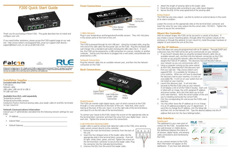
RLE Technologies
RLE Technologies Falcon F200 Operating and maintenance instructions
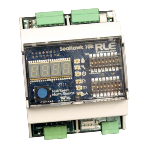
RLE Technologies
RLE Technologies SeaHawk 10K User manual
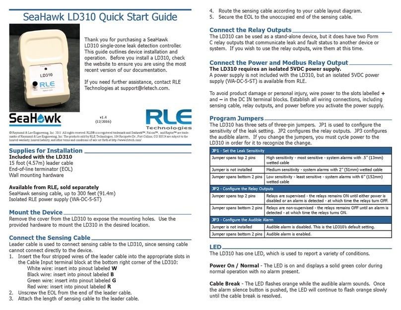
RLE Technologies
RLE Technologies SeaHawk LD310 User manual

RLE Technologies
RLE Technologies LD1500 User manual

RLE Technologies
RLE Technologies Falcon F200 User manual
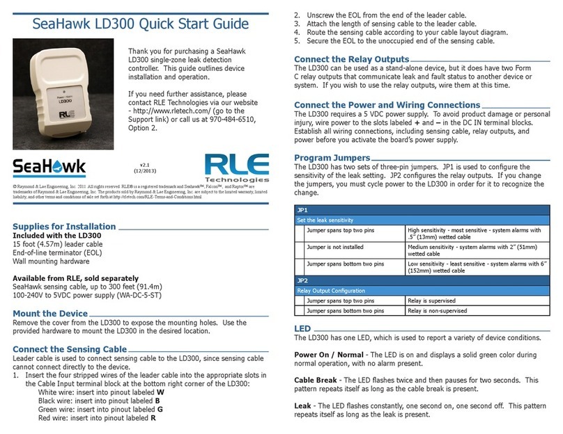
RLE Technologies
RLE Technologies SeaHawk LD300 User manual
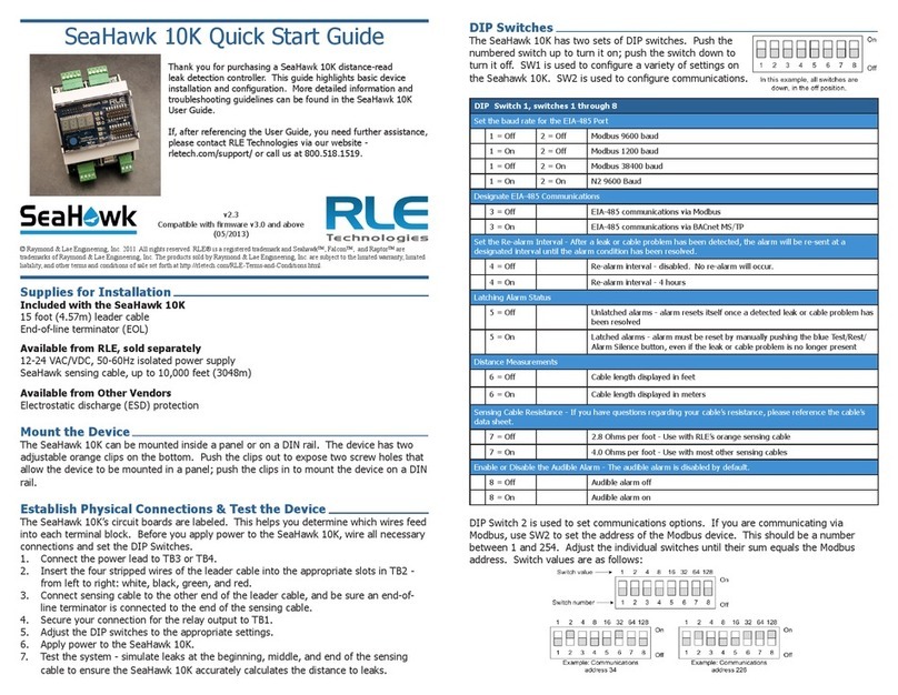
RLE Technologies
RLE Technologies SeaHawk 10K User manual
RLE Technologies
RLE Technologies SeaHawk LD5200 User manual
