manuals.online logo
Brands
  1. Home
  2. •
  3. Brands
  4. •
  5. RLE Technologies
  6. •
  7. Controllers
  8. •
  9. RLE Technologies Falcon F200 User manual

RLE Technologies Falcon F200 User manual

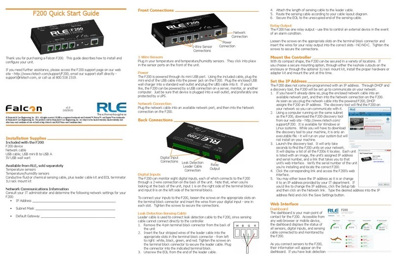
1-Wire Sensor Connections
Plug in your temperature and temperature/humidity sensors. They click into place
in the sensor ports on the front of the unit.
Status LED
The F200 has one multi-color LED on its front side. There are a variety of alarm
and alert patterns and colors programmed for this LED. Use the following chart to
determine which alarms are active on your F200.
Blink Pattern Status Description
Green / Off (Intermittent) Normal status - no alarms are present
Lt. Blue / Blue Alarm - Leak detection cable break
Lt. Blue / Off Alarm - A leak has been detected
Red / Off Alarm - Temperature
Red / Blue Alarm - Humidity
Magenta / Off Alarm - Digital input
Yellow / Off No network connection
White / Off Unit is booting* * Do not access or congure the
F200 while these alerts are active.
Mixed Firmware update is executing*
Red / Magenta Call RLE - the F200 has an internal error
Alarm Silence and System Reset Button
The alarm reset is located on the front of the unit, near the LED. When the audible
alarm is active, push this button once to silence the audible alarm. You’ll know
which alarm is active and associated with the audible alarm because the LED will
blink to indicate a specic alarm condition.
There are several reset functions assigned to this button. Press the button (and
hold when indicated) to achieve the desired functions:
Press Button and Release LED Color Action
One quick beep Blinking LED
error indicator
Silence audible alarm
Press Button and Hold;
Release After
LED Color Action
Two consecutive beeps Green Reset all alarms. If any alarms
are currently active, they will
immediately re-alarm.
Three consecutive beeps Red Toggle the relay output
Four consecutive beeps White Reboot the F200
F200: Rear Connections and Conguration Button
Digital Inputs
The F200 can monitor up to eight digital inputs, each of which connects to the F200
through a 2-wire connection on the back of the unit. When you’re looking at the
back of the unit, note that input 1 is on the right side of the terminal blocks and
input 8 is on the left side of the terminal blocks.
To connect your digital inputs to the F200, loosen the screws on the appropriate
slots on the terminal block connector and insert the two wires from your digital
input - one in each slot. Tighten the screws to secure the connections.
Leak Detection Sensing Cable
Since leak detection sensing cable cannot connect directly to a controller, leader
cable is used to connect leak detection cable to the F200.
1. Remove the 4-pin terminal block connector from the
connection labeled Leak Cable on the back of the unit.
2. Insert the stripped wires of the leader cable into the
appropriate slots in the terminal block connector - from left
to right: white, black, green, red. Tighten the screws on the
connector to secure the wires. Plug the connector - with the
wires in the correct order - into the connection labeled Leak
Cable on the back of the device.
3. Unscrew the EOL from the end of the leader cable.
4. Attach the length of sensing cable to the leader cable.
5. Route the sensing cable according to your cable layout diagram.
6. Secure the EOL to the unoccupied end of the sensing cable.
Relay Output
The F200 has one relay output - use this to control an external device in the event
of an alarm condition. Loosen the screws on the appropriate slots on the terminal
block connector and insert the wires for your relay output into the correct slots -
NC-NO-C. Tighten the screws to secure the connections.
Conguration Button
The conguration button is used for advanced troubleshooting. This button needs
to be accessed with the tip of a small object, like a paperclip. Insert it into the hole
and press the button (and hold when indicated) to achieve the desired functions:
Press Button and Release Action
One beep Temporarily enables DHCP. The F200 will remain
this way until it is rebooted, power is cycled, or the
IP is congured. See the F200 Startup Guide for
more information on DHCP and IP addressing.
Press Button and Hold;
Release After
Action
Two consecutive beeps Temporarily set the unit’s static IP address to
10.0.0.188. The F200 will remain this way
until it is rebooted, power is cycled, or the IP is
congured. See the F200 Startup Guide for more
information on DHCP and IP addressing.
Three consecutive beeps Disables the administrator password.
Four consecutive beeps Reset to all factory default settings
Mount the Controller
Once all connections have been wired to the F200, mount the device in an
appropriate location. RLE recommends a secure mounting option through either
the keyhole cutouts on the enclosure or through the optional 1U rack mount kit.
Web Interface
Dashboard
Accessible from any web browser or mobile device, the Dashboard includes the
status of all sensors, digital inputs, and sensing cables the F200 monitors. As
sensors are connected to the F200, their readings appear on the Dashboard. If
leak detection cable is connected to the F200, use the Inputs tab on
the Setup menu to enable leak detection monitoring and its Dashboard
display.
© Raymond & Lae Engineering, Inc. 2011. All rights reserved. RLE® is a registered trademark and Seahawk™, Falcon™, and Raptor™ are trademarks
of Raymond & Lae Engineering, Inc. The products sold by RLE Technologies, 104 Racquette Dr., Fort Collins, CO 80524 are subject to the limited war-
ranty, limited liability, and other terms and conditions of sale set forth at http://www.rletech.com/.
Before you begin, be sure you have access to the following equipment
and information - if applicable:
F200 device
Temperature and temperature/humidity sensors
Conductive uid or chemical sensing cable, plus leader cable kit and EOL terminator
1U rack mount bracket
The F200’s serial number is found on the white sticker afxed to the bottom of the
unit.
• Serial Number ____________________________________________
• IP Address _______________________________________________
Before you congure the F200, complete ALL STEPS in the F200 Startup
Guide. The F200 should be powered up and you should be able to access
the F200’s web interface Dashboard via the unit’s IP address or NetBIOS.
F200: Front Connections, Silence/Reset Button, and LED
F200 Conguration Guide
Thank you for purchasing a Falcon F200. This Conguration Guide is the second
step in the F200 installation process. Before you use this guide, be sure you’ve
completed all the steps in the F200 Startup Guide. Both documents are packaged
with the F200 and available in the support section of our website, rletech.com.
Before you begin to congure your device consult our website to ensure you’re
working with the most recent version of documentation for this product.
If you need further assistance, contact RLE Technologies at [email protected].
Network
Connection
Power
Connection
1-Wire Sensor
Connections
Status
LED
Silence/Reset
Button
Leak Detection
Leader Cable
Connection
Relay
Output
Digital Input
Connections
Conguration
Button
Leak Detection Leader
Cable Terminal Block
Connection Wiring
Order
v4.2
Compatible with rmware version 4100.7 and above
(1/2017)
graph and zoom into it, or use the slider bars beneath the graph to adjust the range
of the graph. Double click anywhere on the graph to return to the default view.
The sample period designates the amount of time that passes between logged data
points on the trending graph, and can be set from ten seconds to one day. The
F200 records up to 86,400 points - a shorter sample period records more closely
grouped points for a shorter overall period of time, while a larger sample period
charts data points spaced farther apart, but over a greater overall period of time.
The trending log is downloadable as a CSV le.
Enabling event logging generates a table on the Dashboard that logs all major
alarm and return to normal events with a date and time stamp.
SNMPv2 and Modbus TCP
The F200 can be congured to communicate via SNMPv2 and Modbus TCP. If you
wish to use this functionality, congure the settings on this page. Note that links in
these headings allow you to download the SNMPv2 MIB le and to view the current
readings of all the F200’s Modbus TCP registers. A separate document, available in
the Support section of RLE’s website, further details the F200’s Modbus capabilities.
Admin
Firmware Updates
Determine the current version and build of
rmware running on your F200. Compare
this with the rmware posted on the F200
Support page on the RLE website. If a
newer version of rmware is available,
download it and save it to a local computer.
Manually upload it to your F200 using the
Upload Firmware File link. The update will take a few minutes and the F200 will
reboot itself once the new rmware is installed. Once the reboot is complete, the
F200 will be ready to resume its operations.
System Controls
The reboot button allows users to remotely reboot the F200. Use the Identify
button to make the unit’s LED ash and its audible alarm to sound. This helps
users connect a web interface with an actual physical unit.
Users
Two types of users can be congured on the F200. Up to eight usernames can be
congured in each of the two categories. Each username can be used by only one
user at a time. Each user should have their own username:
• Admin User - Admin Users can view and edit the F200’s Setup screens. For
admin users, the default username is admin; the default password is admin.
• Normal User - Normal (Read Only) Users can only view the F200’s Dashboard.
There are three login congurations:
• Never - Users are never required to log in. Anyone can view the Dashboard
and Setup screens, and anyone can change the F200’s conguration through
the Setup screens.
• To Change Settings - A login is NOT required to view the Dashboard. Only
users logged in as Admin Users can view and edit the Setup screens.
• Always - All users are required to log in. View-Only Users can only view the
Dashboard. Admin Users can also view and edit Setup screens.
A relay control checkbox is also located on this page. If you check this checkbox,
only Admin users will be able to operate the Relay button on the Dashboard.
Logout
If you’re logged in to the F200 and have nished your conguration work, click this
link. It will log you out of the device and return the view via your workstation back
to its read-only state.
Setup Menus
When you begin typing changes into the elds, they will turn either green to
indicate your changes are acceptable, or red to indicate your changes cannot be
submitted. If a eld turns red, you’ve likely typed more characters than the eld
can accept or you’ve entered a character that can’t be used in that eld. Once you
delete the excess or offending character, the eld will turn green again.
When you edit a section, a Save Settings button appears at the bottom of that
section. Click this button to save your changes. Changes will neither be saved
nor implemented until you click the Save Settings button.
Network
Use the network tab to congure IP settings and view the current IP conguration.
The F200 Startup Guide, packaged with this product and available at rletech.com,
details this process.
Time is also set on the network tab. Two timekeeping options are available:
1. Network time protocol (NTP) is enabled by default, accessing pool.ntp.org as
the NTP server.
2. The F200 also has an onboard real-time clock (RTC). To use the RTC:
a. UNCHECK the NTP Enabled checkbox. If you do not uncheck this box,
NTP will still be active and will override any RTC settings.
b. Enter data in the Set Date/Time eld, paying careful attention to syntax.
If you do not use the correct syntax, this eld will turn red and you will
not be able to submit your date and time settings.
c. Click the Save Settings button. NTP is now disabled and RTC is enabled.
Sensors
Use the sensors tab to congure information, alarm parameters, and alarm
notication (email, audible, activate relay output, etc.) for each 1-wire sensor that
is currently connected to the F200. Congure each sensor separately and click the
Save Settings button after you have entered settings for each sensor.
Inputs
Leak Detection
The F200 monitors up to 200 feet of leak detection cable, congured in a single
zone. If you have leak detection cable connected to the F200 you will
need to use this menu to enable the leak detection monitoring. Once leak
detection is enabled, the leak detection cable widget appears on the Dashboard.
When you congure the sensitivity for the cable, keep in mind:
• Low sensitivity: more water is required to trigger a leak alarm.
• High sensitivity: less water is required to trigger a leak alarm.
Digital Inputs
Use the inputs tab to name your digital inputs and to congure alarm and
notication parameters (email, audible, enable relay output, etc.) for each input.
Keep in mind the “When” box will tell the F200 when to send an alarm. For
instance, if your digital input is normally open, the F200 should generate an alarm
WHEN that contact is closed. So for that input, you’d select “Closed” in the When
drop down, and then decide what notication action the F200 should take.
Network Links
You can congure up to four network link widgets that allow you to display a static
or IP web camera image and then link to any URL from the Dashboard. Congure
each link and click the Save Settings button to enable this feature.
Reporting
Email Notications
Use this feature to send email alerts when the F200 goes into alarm. Users entered
as email recipients will receive all email alerts generated by the F200. Email
conguration is specic to your email provider and settings - if you are unsure of
the appropriate email conguration settings, contact your IT Department. Sample
email congurations are as follows:
Once you save any changes made within this section, a test email button appears.
Send a test email to ensure your notications are working correctly, and that your
spam lter hasn’t blocked the incoming email notications.
Dashboard Options
Designate English (Fahrenheit and feet) or metric (Celsius and meters) units. By
default, the F200 is congured for English readings.
Relay Output
When you enable the relay output, a button to control
the relay output appears on the Dashboard. The button
allows approved users to open and close the relay output
from the F200’s Dashboard. Use the options to congure
the button’s labels. Any alarm condition that is
congured to change the state of the relay output
will override the manual button control of the
relay. If an alarm is active, you cannot turn off
the alarm with the manual relay control button.
Trending and Logging
Once trending is enabled, a graph will appear on the Dashboard. To examine the
points on the graph in greater detail, use your mouse to highlight a section of the
Encrypted SMTP Server Setup
Gmail SMTP Server Setup
1. Set up a Gmail smtp-relay account:
• https://support.google.com/a/
answer/176600?hl=en
2. Set up a Google Apps SMTP relay:
• https://support.google.com/a/
answer/2956491
Outlook Email Server Setup
Use the Ofce 365 or Outlook Direct
Send conguration. See Option 2 at:
• https://technet.microsoft.com/en-us/
library/dn554323(v=exchg.150).aspx
Hardware Version
Firmware Version
Firmware Build
(Numbers before dash)
(Numbers after dash)
SMTP Server: somedomain-com.mail.protection.outlook.com
Basic SMTP Server/Recipient Setup

This manual suits for next models

1

Other RLE Technologies Controllers manuals

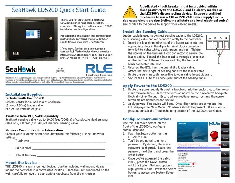
RLE Technologies SeaHawk LD5200 User manual

RLE Technologies

RLE Technologies SeaHawk LD5200 User manual

RLE Technologies SeaHawk LD310 User manual

RLE Technologies

RLE Technologies SeaHawk LD310 User manual

RLE Technologies LD1500 User manual

RLE Technologies

RLE Technologies LD1500 User manual

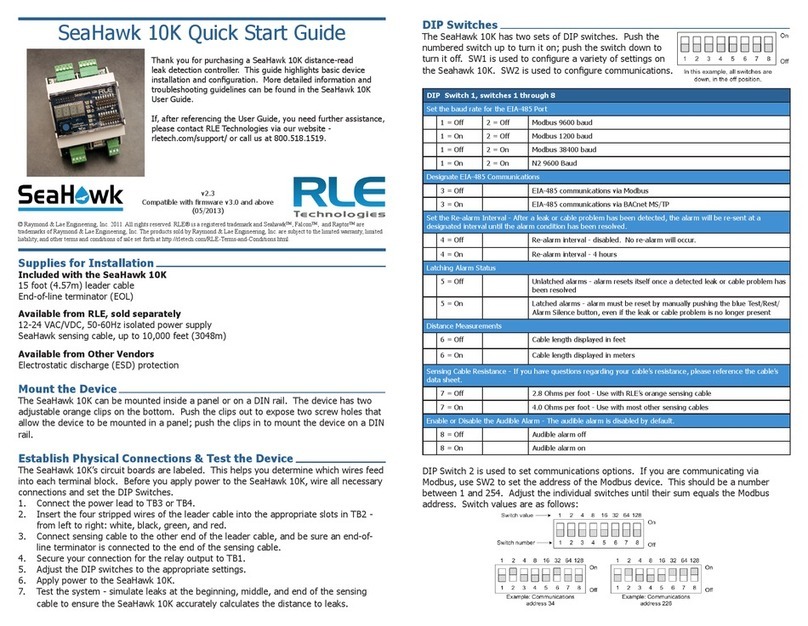
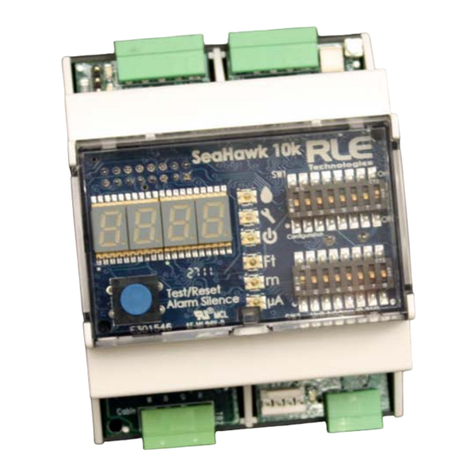
RLE Technologies SeaHawk 10K User manual

RLE Technologies

RLE Technologies SeaHawk 10K User manual

RLE Technologies SeaHawk 10K User manual

RLE Technologies

RLE Technologies SeaHawk 10K User manual

RLE Technologies SeaHawk LD5200 User manual

RLE Technologies

RLE Technologies SeaHawk LD5200 User manual

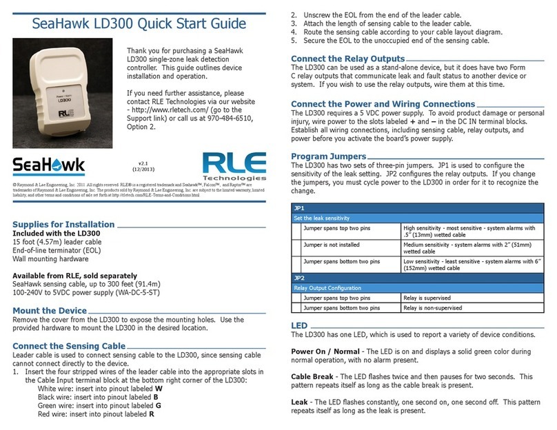
RLE Technologies SeaHawk LD300 User manual

RLE Technologies

RLE Technologies SeaHawk LD300 User manual

RLE Technologies Falcon F200 Operating and maintenance instructions

RLE Technologies

RLE Technologies Falcon F200 Operating and maintenance instructions

Popular Controllers manuals by other brands

CSE Unidrive M700 user guide

CSE

CSE Unidrive M700 user guide

Eurotops TH-230BH instructions

Eurotops

Eurotops TH-230BH instructions

Vector TCI-C Series manual

Vector

Vector TCI-C Series manual

lrritrol Rain Dial RD-600 user guide

lrritrol

lrritrol Rain Dial RD-600 user guide

Simons Voss Technologies Allegion PegaSys quick guide

Simons Voss Technologies

Simons Voss Technologies Allegion PegaSys quick guide

Trane Symbio 210 Installation, operation and maintenance

Trane

Trane Symbio 210 Installation, operation and maintenance

Mitsubishi Electric FX Series Training manual

Mitsubishi Electric

Mitsubishi Electric FX Series Training manual

Dungs GasMultiBloc MB-ZRD B07 Series Operation and assembly instructions

Dungs

Dungs GasMultiBloc MB-ZRD B07 Series Operation and assembly instructions

BST ekr 500 Plus Quick reference guide

BST

BST ekr 500 Plus Quick reference guide

Zennio MAXinBOX 24 ZIO-MB24 user manual

Zennio

Zennio MAXinBOX 24 ZIO-MB24 user manual

Datapath VSN400 Series quick start guide

Datapath

Datapath VSN400 Series quick start guide

Collamat C9100 Technical handbook

Collamat

Collamat C9100 Technical handbook

ABB ACS 600 MultiDrive installation guide

ABB

ABB ACS 600 MultiDrive installation guide

ABB i-bus KNX product manual

ABB

ABB i-bus KNX product manual

Datapath x Series quick start guide

Datapath

Datapath x Series quick start guide

Newport Pt32 Operator's manual

Newport

Newport Pt32 Operator's manual

Oracle SGSN06 user guide

Oracle

Oracle SGSN06 user guide

Control Data 3234 Series Hardware reference manual

Control Data

Control Data 3234 Series Hardware reference manual

manuals.online logo
manuals.online logoBrands
  • About & Mission
  • Contact us
  • Privacy Policy
  • Terms and Conditions

Copyright 2025 Manuals.Online. All Rights Reserved.