RLE Technologies SeaHawk 10K User manual

User Guide
10K
www.rletech.com RLE Technologies 800.518.1519
User Guide Version 05.22
Documented Using Firmware Version 3.2

2 SeaHawk 10K User Guide 800.518.1519
Copyright and Trademark Notices
© Raymond & Lae Engineering, Inc. 2011. All rights reserved. RLE® is a registered trademark and
SeaHawk™, Falcon™, and Raptor™ are trademarks of Raymond & Lae Engineering, Inc. The
products sold by Raymond & Lae Engineering, Inc. are subject to the limited warranty, limited liability,
and other terms and conditions of sale set forth at http://www.rletech.com/.
Revision History
Rev. No. Date Rev. No. Date
1.0 April 2011 2.7 December 2016
1.1 May 2011 05.22 May 2022
2.0 August 2011
2.1 December 2011
2.2 November 2012
2.3 August 2013
2.4 August 2013
2.5 September 2013
2.5.a July 2014
2.6 September 2015

rletech.com SeaHawk 10K User Guide 3
Manufacturer’s Notes
This product is manufactured by RLE Technologies, 104 Racquette Drive, Fort Collins, CO, 80524.
If this product is used in any manner other than that specified by the manufacturer, the protection
provided by the equipment may be impaired.
Product Warranty
Warranty information for RLE products can be found at www.rletech.com.
Product Registration
Product registration helps RLE Technologies inform owners of:
• Product upgrades
• Firmware enhancements
• New products and technologies
• Special offers available only to registered users
Any information provided to RLE Technologies through the registration form will be regarded as
confidential. RLE will not sell or distribute any of the information to third parties.
Technical Support
Before you install a 10K, refer to RLE Technologies’ website, www.rletech.com, to ensure you are
using the most recent version of all documentation.
Personal assistance is available Monday through Friday, from 8:00 a.m. to 5:00 p.m. Mountain Time.
A request for assistance may be sent to [email protected].
Otherwise, please call us directly at: 800.518.1519.
The following information is located on the bottom of each SeaHawk 10K unit. Please have this
information available whenever a technical support call is placed:
The 10K is not a field-serviceable item and must be sent back to RLE Technologies for mechanical
repair. Power must be disconnected (unplugged) from the 10K any time the unit is mechanically
serviced. Physically unplug power from the unit any time you are making wiring connections to or from
the 10K.
RLE cannot accept an item for repair without a Return Materials Authorization number, which must be
provided by RLE.
Product Model Number
Product Serial Number
Product Manufacture Date

rletech.com SeaHawk 10K User Guide 4

Contents
rletech.com SeaHawk 10K User Guide 5
1 Product Overview . . . . . . . . . . . . . . . . . . . . . . . . . . . . . . . . . . . . . . . . . . . . . . . . . . .11
Description . . . . . . . . . . . . . . . . . . . . . . . . . . . . . . . . . . . . . . . . . . . . . . . . . . . . . . . . . . . . . . . . . . . . . . 11
Operation . . . . . . . . . . . . . . . . . . . . . . . . . . . . . . . . . . . . . . . . . . . . . . . . . . . . . . . . . . . . . . . . . . . . . . . 11
2 Installation and Configuration . . . . . . . . . . . . . . . . . . . . . . . . . . . . . . . . . . . . . . . .13
Prepare for Installation . . . . . . . . . . . . . . . . . . . . . . . . . . . . . . . . . . . . . . . . . . . . . . . . . . . . . . . . . . . . . 13
Physical Connection Overview . . . . . . . . . . . . . . . . . . . . . . . . . . . . . . . . . . . . . . . . . . . . . . . . . . . . . . . 13
Mount the SeaHawk 10K . . . . . . . . . . . . . . . . . . . . . . . . . . . . . . . . . . . . . . . . . . . . . . . . . . . . . . . . . . . 14
Establish Physical Connections . . . . . . . . . . . . . . . . . . . . . . . . . . . . . . . . . . . . . . . . . . . . . . . . . . . . . . 15
TB1: Summary Relay (optional) . . . . . . . . . . . . . . . . . . . . . . . . . . . . . . . . . . . . . . . . . . . . . . . . . . 15
TB2: Leader Cable . . . . . . . . . . . . . . . . . . . . . . . . . . . . . . . . . . . . . . . . . . . . . . . . . . . . . . . . . . . . 16
TB3 and TB4: Input Power and EIA-485 Communications Port . . . . . . . . . . . . . . . . . . . . . . . . . 17
JMP - Termination Jumper. . . . . . . . . . . . . . . . . . . . . . . . . . . . . . . . . . . . . . . . . . . . . . . . . . . . . . 19
Select Alarm Options . . . . . . . . . . . . . . . . . . . . . . . . . . . . . . . . . . . . . . . . . . . . . . . . . . . . . . . . . . . . . . 19
Enable and Disable the Audible Alarm. . . . . . . . . . . . . . . . . . . . . . . . . . . . . . . . . . . . . . . . . . . . . 19
Set the Re-Alarm Interval. . . . . . . . . . . . . . . . . . . . . . . . . . . . . . . . . . . . . . . . . . . . . . . . . . . . . . . 20
Connect the SeaHawk Leak Detection Cable . . . . . . . . . . . . . . . . . . . . . . . . . . . . . . . . . . . . . . . . . . . . 20
Connect Lengths of Sensing Cable . . . . . . . . . . . . . . . . . . . . . . . . . . . . . . . . . . . . . . . . . . . . . . . 20
Secure Sensing Cable to the Floor . . . . . . . . . . . . . . . . . . . . . . . . . . . . . . . . . . . . . . . . . . . . . . . 21
Apply Power to the SeaHawk 10K . . . . . . . . . . . . . . . . . . . . . . . . . . . . . . . . . . . . . . . . . . . . . . . . . . . . 22
Test the System . . . . . . . . . . . . . . . . . . . . . . . . . . . . . . . . . . . . . . . . . . . . . . . . . . . . . . . . . . . . . . . . . . 22
3 Operation . . . . . . . . . . . . . . . . . . . . . . . . . . . . . . . . . . . . . . . . . . . . . . . . . . . . . . . . .25
Front Panel Controls and Display . . . . . . . . . . . . . . . . . . . . . . . . . . . . . . . . . . . . . . . . . . . . . . . . . . . . . 25
Manage Alarms . . . . . . . . . . . . . . . . . . . . . . . . . . . . . . . . . . . . . . . . . . . . . . . . . . . . . . . . . . . . . . . . . . . 27
4 Modbus Communication . . . . . . . . . . . . . . . . . . . . . . . . . . . . . . . . . . . . . . . . . . . . . 29
Modbus Implementation Basics . . . . . . . . . . . . . . . . . . . . . . . . . . . . . . . . . . . . . . . . . . . . . . . . . . . . . . 29
Modes of Transmission . . . . . . . . . . . . . . . . . . . . . . . . . . . . . . . . . . . . . . . . . . . . . . . . . . . . . . . . 29
Slave Address Field. . . . . . . . . . . . . . . . . . . . . . . . . . . . . . . . . . . . . . . . . . . . . . . . . . . . . . . . 29
Function Field . . . . . . . . . . . . . . . . . . . . . . . . . . . . . . . . . . . . . . . . . . . . . . . . . . . . . . . . . . . . 29
Data Field . . . . . . . . . . . . . . . . . . . . . . . . . . . . . . . . . . . . . . . . . . . . . . . . . . . . . . . . . . . . . . . 30
Error Check (Checksum) Field . . . . . . . . . . . . . . . . . . . . . . . . . . . . . . . . . . . . . . . . . . . . . . . 30
5-1.2 Exception Responses. . . . . . . . . . . . . . . . . . . . . . . . . . . . . . . . . . . . . . . . . . . . . . . . . . 30
Packet Communications for the SeaHawk 10K . . . . . . . . . . . . . . . . . . . . . . . . . . . . . . . . . . . . . . . . . . 31
Function 03: Read Output Registers . . . . . . . . . . . . . . . . . . . . . . . . . . . . . . . . . . . . . . . . . . . . . . 31
Function 04: Read Input Registers. . . . . . . . . . . . . . . . . . . . . . . . . . . . . . . . . . . . . . . . . . . . . . . . 33
RTU Framing. . . . . . . . . . . . . . . . . . . . . . . . . . . . . . . . . . . . . . . . . . . . . . . . . . . . . . . . . . . . . . . . . . . . . 34
Calibrate Cable Length via Modbus . . . . . . . . . . . . . . . . . . . . . . . . . . . . . . . . . . . . . . . . . . . . . . . . . . . 35
5 Preventive Maintenance . . . . . . . . . . . . . . . . . . . . . . . . . . . . . . . . . . . . . . . . . . . . . .37
6 Troubleshooting . . . . . . . . . . . . . . . . . . . . . . . . . . . . . . . . . . . . . . . . . . . . . . . . . . . .39
A Configuration Reference . . . . . . . . . . . . . . . . . . . . . . . . . . . . . . . . . . . . . . . . . . . . .41
DIP Switches. . . . . . . . . . . . . . . . . . . . . . . . . . . . . . . . . . . . . . . . . . . . . . . . . . . . . . . . . . . . . . . . . . . . . 41
DIP SW1 Settings . . . . . . . . . . . . . . . . . . . . . . . . . . . . . . . . . . . . . . . . . . . . . . . . . . . . . . . . . . . . . . . . . 42
DIP SW2 Settings . . . . . . . . . . . . . . . . . . . . . . . . . . . . . . . . . . . . . . . . . . . . . . . . . . . . . . . . . . . . . . . . . 43

Figures
rletech.com SeaHawk 10K User Guide 7
1 Product Overview . . . . . . . . . . . . . . . . . . . . . . . . . . . . . . . . . . . . . . . . . . . . . . . . 11
2 Installation and Configuration . . . . . . . . . . . . . . . . . . . . . . . . . . . . . . . . . . . . . 13
Figure 2.1 SeaHawk 10K Physical Inputs. . . . . . . . . . . . . . . . . . . . . . . . . . . . . . . . . . . . 14
Figure 2.2 Mount the SeaHawk 10K. . . . . . . . . . . . . . . . . . . . . . . . . . . . . . . . . . . . . . . . 14
Figure 2.3 Relay Output (TB1) and Sensing Cable Connection (TB2) . . . . . . . . . . . . . . 15
Figure 2.4 Power and Communications Connections (TB3 and TB4) and Termination
Jumper (JMP) 15
Figure 2.5 Relay Output Connection TB1. . . . . . . . . . . . . . . . . . . . . . . . . . . . . . . . . . . . 15
Figure 2.6 General DIP Switch Settings . . . . . . . . . . . . . . . . . . . . . . . . . . . . . . . . . . . . . 16
Figure 2.7 DIP Switch 5, SW1 - Latched or Unlatched Alarms. . . . . . . . . . . . . . . . . . . . 16
Figure 2.8 Cable Connection TB2 . . . . . . . . . . . . . . . . . . . . . . . . . . . . . . . . . . . . . . . . . 16
Figure 2.9 DIP Switch 6, SW1 - Display Cable Length in Feet or Meters. . . . . . . . . . . . 17
Figure 2.10 DIP Switch 7, SW1 - Ohms per Foot Resistance . . . . . . . . . . . . . . . . . . . . . 17
Figure 2.11 TB3 and TB4 Power Supply and Communications Connections . . . . . . . . . 18
Figure 2.12 DIP Switch Settings for Communications Baud Rate . . . . . . . . . . . . . . . . . . 18
Figure 2.13 SW2 DIP Switch Settings for Communications Address . . . . . . . . . . . . . . . . 19
Figure 2.14 DIP Switch 8, SW 1 - Audible Alarm Settings . . . . . . . . . . . . . . . . . . . . . . . . 19
Figure 2.15 DIP Switch 4, SW1 - Re-Alarm Interval . . . . . . . . . . . . . . . . . . . . . . . . . . . . . 20
Figure 2.16 SeaHawk Sensing Cable. . . . . . . . . . . . . . . . . . . . . . . . . . . . . . . . . . . . . . . . 20
Figure 2.17 Secure the Cable. . . . . . . . . . . . . . . . . . . . . . . . . . . . . . . . . . . . . . . . . . . . . . 21
3 Operation . . . . . . . . . . . . . . . . . . . . . . . . . . . . . . . . . . . . . . . . . . . . . . . . . . . . . . 25
Figure 3.1 Front Panel Controls and Display . . . . . . . . . . . . . . . . . . . . . . . . . . . . . . . . . 25
4 Modbus Communication . . . . . . . . . . . . . . . . . . . . . . . . . . . . . . . . . . . . . . . . . . 29
Figure 4.1 DIP Switch Settings for Ohms/Foot . . . . . . . . . . . . . . . . . . . . . . . . . . . . . . . . 35
Figure 4.2 Formula for Calculating Exact Cable Resistance . . . . . . . . . . . . . . . . . . . . . 35
5 Preventive Maintenance . . . . . . . . . . . . . . . . . . . . . . . . . . . . . . . . . . . . . . . . . . 37
6 Troubleshooting . . . . . . . . . . . . . . . . . . . . . . . . . . . . . . . . . . . . . . . . . . . . . . . . . 39
A Configuration Reference . . . . . . . . . . . . . . . . . . . . . . . . . . . . . . . . . . . . . . . . . . 41
Figure A.1 General Dip Switch Settings . . . . . . . . . . . . . . . . . . . . . . . . . . . . . . . . . . . . . 41
Figure A.2 SW1 Dip Switch Configuration Settings . . . . . . . . . . . . . . . . . . . . . . . . . . . . 42
Figure A.3 SW2 DIP Switch Settings for Modbus Unit Address . . . . . . . . . . . . . . . . . . . 43

8 SeaHawk 10K User Guide 800.518.1519

Tables
rletech.com SeaHawk 10K User Guide 9
1 Product Overview . . . . . . . . . . . . . . . . . . . . . . . . . . . . . . . . . . . . . . . . . . . . . . . . . . 11
2 Installation and Configuration . . . . . . . . . . . . . . . . . . . . . . . . . . . . . . . . . . . . . . . . 13
3 Operation . . . . . . . . . . . . . . . . . . . . . . . . . . . . . . . . . . . . . . . . . . . . . . . . . . . . . . . . . 25
Table 3.1 Front Panel Controls and Displays . . . . . . . . . . . . . . . . . . . . . . . . . . . . . . . . . . 26
4 Modbus Communication . . . . . . . . . . . . . . . . . . . . . . . . . . . . . . . . . . . . . . . . . . . . 29
Table 4.1 Exception Codes . . . . . . . . . . . . . . . . . . . . . . . . . . . . . . . . . . . . . . . . . . . . . . . . 30
Table 4.2 Read Output Register Packet Structure . . . . . . . . . . . . . . . . . . . . . . . . . . . . . . 31
Table 4.3 Output Registers . . . . . . . . . . . . . . . . . . . . . . . . . . . . . . . . . . . . . . . . . . . . . . . . 31
Table 4.4 Read Input Registers Packet Structure . . . . . . . . . . . . . . . . . . . . . . . . . . . . . . . 33
Table 4.5 Input Registers . . . . . . . . . . . . . . . . . . . . . . . . . . . . . . . . . . . . . . . . . . . . . . . . . 33
Table 4.6 Status Flags (Register 30001) . . . . . . . . . . . . . . . . . . . . . . . . . . . . . . . . . . . . . 34
Table 4.7 Response Sample. . . . . . . . . . . . . . . . . . . . . . . . . . . . . . . . . . . . . . . . . . . . . . . 34
5 Preventive Maintenance . . . . . . . . . . . . . . . . . . . . . . . . . . . . . . . . . . . . . . . . . . . . . 37
6 Troubleshooting . . . . . . . . . . . . . . . . . . . . . . . . . . . . . . . . . . . . . . . . . . . . . . . . . . . 39
Table 6.1 Troubleshooting . . . . . . . . . . . . . . . . . . . . . . . . . . . . . . . . . . . . . . . . . . . . . . . . 39
A Configuration Reference . . . . . . . . . . . . . . . . . . . . . . . . . . . . . . . . . . . . . . . . . . . . 41

10 SeaHawk 10K User Guide 800.518.1519

rletech.com SeaHawk 10K User Guide 11
CHAPTER
1
CHAPTER 0PRODUCT OVERVIEW
1.1. Description
As RLE’s most cost effective distance-read leak detection solution, the SeaHawk 10K reports
the presence of water and other liquids as detected by sensing cable.
Capable of accommodating up to 10,000 feet (3048m) of sensing cable, the SeaHawk 10K has
an audible alarm and can communicate via Modbus. As a stand-alone solution, the
SeaHawk 10K provides alarm notification and numeric distances on its front panel.
Integration into a Modbus network allows the activity and status of one or multiple
SeaHawk 10Ks to be managed from one central location.
1.2. Operation
Supervised System
The SeaHawk 10K is a supervised system – it continually monitors sensing cable and spot
detectors for continuity – and produces alarms for the following conditions:
Leak detection
Cable break
Cable contamination
Distance-Read Leak Detection
When the SeaHawk 10K's circuitry measures a current in excess of the user-defined leak
threshold, the unit's microprocessor computes the distance to the leak. The SeaHawk 10K then
annunciates the leak and communicates via Modbus to a master controller or a Modbus-
equipped monitoring system. The summary relay sends notification to an alarm panel or
monitoring system.

12 SeaHawk 10K User Guide 800.518.1519
1 Product Overview
User Configuration and Communication
The SeaHawk 10K’s front panel display – which includes a four-digit LED panel and six LED
indicators – provides information about its status, including the following:
Leak detected
Cable fault detected
Power status
Configured unit of measure
Leak detection cable’s amperage value
Distance to leak or contamination
Length of installed leak detection cable
Self-test results
The two blocks of DIP switches on the SeaHawk 10K’s front panel are used for configuration.
DIP SW1 configures parameters such as leak and contamination thresholds, latching alarms,
and realarm time interval. DIP SW2 is used to set the Modbus address information for the unit.
The SeaHawk 10K also provides configuration capability and status information to a Modbus-
equipped system via its EIA-485 port.

rletech.com SeaHawk 10K User Guide 13
CHAPTER
2
CHAPTER 0INSTALLATION AND CONFIGURATION
2.1. Prepare for Installation
To install the SeaHawk 10K, you’ll need following supplies:
Included with the SeaHawk 10K
15 foot (4.57m) leader cable
End-of-line terminator (EOL)
Available from RLE, sold separately
Isolated power supply - 24VDC (RLE part PSWA-DC-24-ST) or 24VAC (RLE part WA-
AC-24-ST)
SeaHawk Sensing Cable, up to 10,000 feet (3048m)
J-Clips
Available from other vendors
Electrostatic discharge (ESD) protection
2.2. Physical Connection Overview
The SeaHawk 10K contains two circuit boards:
The top circuit board houses operational controls and displays. SeaHawk 10K operational
information is found in Chapter 3.
The lower circuit board houses the connectors for:
– AC/DC power
– Earth ground
– Relay output
– Leak detection cable
– Communications

14 SeaHawk 10K User Guide 800.518.1519
2 Installation and Configuration
Figure 2.1
SeaHawk 10K Physical Inputs
2.3. Mount the SeaHawk 10K
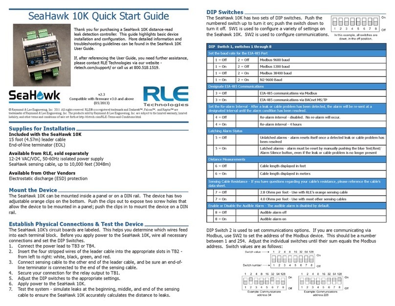
The SeaHawk 10K can be mounted inside a panel or on a DIN rail. The device has two
adjustable orange clips on the bottom. Push the clips out to expose two screw holes that allow
the device to be mounted in a panel; push the clips in to mount it on a DIN rail.
Figure 2.2
Mount the SeaHawk 10K
AC/DC Power Connections (2)
and
EIA-485 Communications Ports (2)
Relay
Output
Sensing Cable
Connection
Termination
Jumper
SW1
Configure
Settings
SW2
Modbus
Configuration
EGND1
Earth Ground
for use with
AC Power

rletech.com SeaHawk 10K User Guide 15
2 Installation and Configuration
2.4. Establish Physical Connections
Figure 2.3
Relay Output (TB1) and Sensing Cable Connection (TB2)
Figure 2.4
Power and Communications Connections (TB3 and TB4) and Termination Jumper
(JMP)
2.4.1 TB1: Summary Relay (optional)
Terminal Block 1 is a Form C relay output. This relay enables alarm notification through a
local or remote panel, master controller, or BMS whenever a leak, cable fault, or cable
contamination is detected.
1Insert the wires into the appropriate slots on TB1 to connect the relay output to the desired
panel or controller.
Figure 2.5
Relay Output Connection TB1
Relay Output
Sensing Cable
Connection
AC/DC Power Connections (2)
and
EIA-485 Communications Ports (2)
Termination Jumper
Earth Ground
for use with
AC Power

16 SeaHawk 10K User Guide 800.518.1519
2 Installation and Configuration
2DIP switches are used to adjust settings on the SeaHawk 10K.
Figure 2.6
General DIP Switch Settings
Use DIP switch 5 on the SW1 DIP switch block to configure this relay as latched or
unlatched.
An unlatched alarm resets itself once a detected leak or cable problem has been resolved.
A latched alarm must be manually reset, even if the detected leak or cable problem is no
longer present.
Figure 2.7
DIP Switch 5, SW1 - Latched or Unlatched Alarms
2.4.2 TB2: Leader Cable
1A 15-foot (4.57m) section of non-sensing leader cable is supplied with each SeaHawk 10K.
The leader cable connects sensing cable to the SeaHawk 10K, since sensing cable cannot
connect directly to the unit. Insert its four stripped wires into the appropriate slots in TB2 –
from left to right: white, black, green, and red.
Figure 2.8
Cable Connection TB2
Note If the terminal connector is removed from the end of the cable, make sure the wires are in
this same order, W - B - G - R, when the connector is reapplied.

rletech.com SeaHawk 10K User Guide 17
2 Installation and Configuration
2Use DIP switch 6 in block SW1 to designate whether the distance on the display is shown in
feet or meters:
Figure 2.9
DIP Switch 6, SW1 - Display Cable Length in Feet or Meters
3RLE’s orange sensing cable has a resistance of 2.8 ohms per foot. Most other sensing cables
have a resistance of 4.0 ohms per foot. If you have questions regarding the resistance of
your cable, please reference the cable’s data sheet. Set DIP switch 7 in block SW1 to the
appropriate resistance-per-foot value.
Figure 2.10
DIP Switch 7, SW1 - Ohms per Foot Resistance
2.4.3 TB3 and TB4: Input Power and EIA-485
Communications Port
The SeaHawk 10K requires an isolated powr supply, either RLE part PSWA-DC-24-ST or
WA-AC-24-ST. A power supply is not included with the SeaHawk 10K and should be
purchased separately from RLE.
An isolated power supply must be provided for the SeaHawk 10K.
Do not connect 120/230 VAC to the unit, or damage will occur to the circuitry.
1Run an isolated power supply to the location of the SeaHawk 10K, or use a DIN rail
mountable power supply and mount it next to the SeaHawk 10K.
2If you are installing just one SeaHawk 10K, use the two left-most pinouts on either TB3 or
TB4 (marked AC/DC) to connect power to the SeaHawk 10K. Insert the positive and
negative wires of the power supply into either of the pinouts; the SeaHawk 10K’s circuitry
will auto-correct.
If you are installing more than one SeaHawk 10K, use TB3 and TB4 to create a daisy-
chained power connection.
3If you are installing just one SeaHawk 10K and it will communicate via Modbus to a
Modbus-enabled controller, use the three right-most pinouts on TB3 or TB4 to connect the
SeaHawk 10K to an EIA-485 network.
WARNING

18 SeaHawk 10K User Guide 800.518.1519
2 Installation and Configuration
If you are installing more than one SeaHawk 10K, use the appropriate pinouts of TB3 and
TB4 to create a daisy-chained Modbus connection.
A grounded shield contact is provided for connection to shielded cable. If the shield contact
is used, verify the power connector is properly grounded and there is no voltage potential
between units on the Modbus network.
Figure 2.11
TB3 and TB4 Power Supply and Communications Connections
4Set the baud rate for the EIA-485 port using DIP switches 1 and 2 on SW1:
Figure 2.12
DIP Switch Settings for Communications Baud Rate
Note The EIA-485 port is set to 8 databits, no parity, and 1 stop bit (8, N, 1).

rletech.com SeaHawk 10K User Guide 19
2 Installation and Configuration
5DIP SW2 is used to set the Modbus address. For further information regarding Modbus
configuration, refer to Section 4.1., “Modbus Implementation Basics” on page 29.
aIf you are communicating via Modbus, you only need to set the Modbus address via
SW2. The Modbus address should be a number between 1 and 254. Adjust the individual
switches until their sum equals the Modbus address. The following illustration shows the
values of the DIP switches on the SW2 block as well as two examples of how the DIP
switches would be set for specific unit addresses.
Figure 2.13
SW2 DIP Switch Settings for Communications Address
2.4.4 JMP - Termination Jumper
The termination jumper, labeled JMP, is located next to TB4. It is used to designate the end of
the line unit In a daisy chain. The SeaHawk 10K ships with the jumper in the non-terminated
position - over the two pins closest to the device enclosure. If your SeaHawk 10K is the only
device in the application, or if it’s not the last unit in the daisy chain, leave the jumper where it
is. If your unit is the last device in a daisy chain, move the jumper so it is over the two pins
nearest the end of the board.
2.5. Select Alarm Options
2.5.1 Enable and Disable the Audible Alarm
The audible alarm is disabled by default. To modify this setting, adjust switch 8 on DIP SW1:
Figure 2.14
DIP Switch 8, SW 1 - Audible Alarm Settings

20 SeaHawk 10K User Guide 800.518.1519
2 Installation and Configuration
2.5.2 Set the Re-Alarm Interval
The SeaHawk 10K can be set to re-alarm – after a leak or cable fault has been detected, the
alarm will be re-sent at a 4 hour interval until the alarm condition has been resolved. This re-
alarm triggers both the audible alarm and the Modbus readout.
The re-alarm option is disabled by default. Activate the re-alarm setting with DIP switch 4 of
SW1:
Figure 2.15
DIP Switch 4, SW1 - Re-Alarm Interval
2.6. Connect the SeaHawk Leak Detection Cable
IMPORTANT To avoid faulty leak detection readings, connect a minimum length of 35 feet (10.7m) of
sensing cable to the SeaHawk 10K.
The SeaHawk 10K is shipped with a 15-foot (4.57m) leader cable. This leader cable was
connected to the SeaHawk 10K in Section 2.4.2 on page 16. The following directions help you
connect sensing cable to the SeaHawk 10K.
2.6.1 Connect Lengths of Sensing Cable
1Unscrew the end-of-line (EOL) terminator from the end of the leader cable.
2Attach the first length of sensing cable to the leader cable. Insert the male pins into the
female connector, and twist the collar on the female side of the connector to secure.
Figure 2.16
SeaHawk Sensing Cable
3Route the sensing cable according to your cable layout diagram. Attach additional lengths
of sensing cable as necessary.
4Secure the EOL terminator to the unoccupied end of the last length of sensing cable.
Note If the EOL terminator is not present at the end of the cable run, a cable fault will register.
5If you are using a reference map, compare it with the actual cable installation. Revise any
discrepancies created through the physical installation of the cable.
Other manuals for SeaHawk 10K
1
Table of contents
Other RLE Technologies Controllers manuals
RLE Technologies
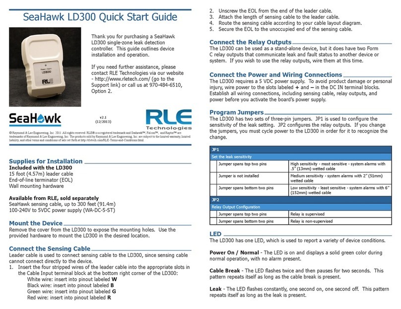
RLE Technologies SeaHawk LD300 User manual

RLE Technologies
RLE Technologies LD1500 User manual
RLE Technologies
RLE Technologies Falcon F200 Operating and maintenance instructions
RLE Technologies
RLE Technologies SeaHawk LD5200 User manual
RLE Technologies
RLE Technologies SeaHawk 10K User manual

RLE Technologies
RLE Technologies Falcon F200 User manual
RLE Technologies
RLE Technologies SeaHawk LD5200 User manual
RLE Technologies
RLE Technologies SeaHawk LD310 User manual


