RLH Industries 16 Channel T1 Over Ethernet Multiplexer... User manual

4 Wire T1
Fiber Link Card System
User Guide
U-001 2019A-0816

RLH Industries, Inc."
Copyright © 2019 RLH Industries, Inc. All rights reserved."
No part of this document may be copied or distributed without
permission.
The RLH logo may not be used for commercial purposes without the
prior written consent of RLH and may constitute trademark infringement.
Other company and product names mentioned herein are trademarks of
their respective companies. Mention of third-party products is for
informational purposes only and constitutes neither an endorsement nor
a recommendation. RLH assumes no responsibility with regard to the
performance or use of these products.#
The information contained in this document is the property of RLH
Industries, Inc. and my not be reproduced or disseminated to third
parties without the express written permission of RLH.#
Every effort has been made to ensure that the information in this
document is accurate. RLH is not responsible for printing or clerical
errors. Because we are constantly seeking ways to improve our
products, specifications and information contained in this document are
subject to change without notice.#
RLH Industries, Inc."
936 North Main Street"
Orange,CA 92867"
"
Ph. 714 532-1672"
email: info@fiberopticlink.com"
www.fiberopticlink.com#
2

Contents
Important information
General Safety Practices%5#
Standards compliance%5#
Description and application%6#
Acronyms%6#
LED status indicators%7#
Before installing
Observe special handling requirements%8#
Set up for installation%9#
Installing card housing%11#
Installing into card housing%11#
Required test equipment%11#
Copper wiring requirements%12#
Verify your installation environment%13#
Installation when T-1 service is available
Connect CO card 14
Set CO card gain 18
Verify CO card operation 19
Connect CO fiber cables 19
Connect Sub card 20
Connect loopback jumpers and power 20
Verify Sub card operation 22
Connect customer premises equipment 23
Installation prior to T1 service availability
Set up CO card 25
Verify CO card operation 27
Connect CO fiber cables 27
Connect Sub card 28
Connect loopback jumpers and power 28
Verify Sub card operation 30
Contents 3

Troubleshooting
Common Issues%31#
CO side troubleshooting%32#
Sub Side troubleshooting%32#
Power supply issues%33#
Verifying fiber cable%34#
Connecting T1 service after installation%36#
NIU Compatibility%36#
Ordering Information
4 Wire T1 Cards%37#
RJ-48C Adapters%37#
Specifications
General Specifications%38#
Support
Technical Support%39#
Contact Information%39
Contents4
Contents

Important information
Intended Audience
This manual is intended for use by field engineering, installation, operation and repair personnel. Every effort has
been made to ensure the accuracy of the information in this manual is accurate. However, due to constant product
improvement, specifications and information contained in this document are subject to change without notice.
Conventions
Symbols for notes, attention, and caution are used throughout this manual to provide readers with additional
information, advice when special attention is needed, and caution to prevent injury or equipment damage.
Notes: Helpful information to assist in installation or operation.
Attention: information essential to installation or operation.
Caution: Important information that may result in equipment damage or injury if ignored.
General Safety Practices
The equipment discussed in this manual may require tools designed for the purpose being described. RLH
recommends that service personnel be familiar with the correct handling and use of any installation equipment
used, and follow all safety precautions including the use of protective personal equipment as required.
Caution - Severe Shock Hazard#
•Never install during a lightning storm or where unsafe high voltages are present.#
•Active T1 lines carry high DC voltages up to 56V. Use caution when handling T1 wiring.#
•Active UHDSL lines carry high DC voltages up to 210V. Use caution when handling UHDSL wiring.#
•Copper power supply wiring may carry high voltages. Remove power from local wiring before servicing.#
Standards compliance
The RLH T1 Fiber Link Card System is compliant with the following industry standards.
NEBS Level 3 FCC PART-15 FCC PART-68B"
IEEE-487 IEEE-1590 Motorola R56"
BR 876-310-100 BT (Telcordia) Bellcore SR-3966 GR-1089"
GR-63 ANSI T1.403
Important Information 5
•Verify or repair before continuing

Description and application
The Fiber Link T1 Model 2 (backwards compatible with the Model 1) System processes incoming bipolar signals
(7.2 V P-P Max) within a bandwidth of 100 KHz to 10 MHz T1 (1.544MbpS) or (CCITT 2.048MbpS), optically
transmits these signals over fiber optic cable and converts the signal to the original electrical signal with minimal
gain or loss.
Output to the copper line is automatically maintained at a nominal level. The Fiber Link system is compatible with
European E1. Transient voltages appearing on or between the 4 wire pairs and/or power supply input are limited by
thermistors, gas tubes and MOVs.
Acronyms
Commonly used acronyms and abbreviations
Color abbreviations
Acronym/Abbreviation
Description
B8ZS
Bipolar 8 Zero Substitution
AMI
Alternate Mark Inversion
CFJ
Copper Fiber Junction (also referred to as Demarc)
CO
Central Office
CPE
Customer Premises Equipment
Demarc
Location of RLH CO equipment and Telco connection
GPR
Ground Potential Rise
LED
Light Emitting Diode
Sub
Subscriber
NIU
Network Interface Unit
RX
Receive
TX
Transmit
P-P
Peak-to-peak (Commonly used with voltage measurements)
Abbreviation
Color
BLU
Blue
GRN
Green
ORG
Orange
RED
Red
YEL
Yellow
Important Information6

LED status indicators
!
OUTPUT 24-56VDC
AUX. P.S. INPUT
FIBR RCV XMIT LIMIT PWRALARM
RX TX
YEL - FIBER
RED - ALARM
GRN - RCV
BLU - PWR
ORG - LIMIT
GRN - XMIT
LED
Color
ON condition
OFF condition
FIBR"
(Fiber Test)
YEL
•“Fiber signal” switch SW2 is ON at !
the far end card.
•Fiber test signal is being received.
•Normal operation!
(“Fiber Signal” switch is !
OFF at the far end card)
•If SW2 is ON on far end card,
check fiber continuity
ALRM"
(Alarm)
RED
Signal is below minimum operating level
Normal operation
RCV"
(Receive)
GRN
Signal is received from fiber
Normal operation
XMIT!
(Transmit)
GRN
Signal is received at copper input
Normal operation
LIMIT
ORG
Copper input signal overload
Normal operation
PWR!
(Power)
BLU
DC power is connected
No DC power is connected
Important Information 7

Before installing
Observe special handling requirements
1.1 Be careful when handling electronic components
!
•This product contains static sensitive components. #
•Handle the T1 cards at their edges only.#
•Follow proper electrostatic discharge procedures.#
This card utilizes circuitry that can be damaged by static electricity. When transporting the card, carry it in an ESD safe
container such as the antistatic bag provided with the card. Before handling cards, discharge yourself of static electricity by
physical bodily contact with earth ground. When handling cards, hold by outer edges and avoid touching circuitry. Failure to
follow ESD precautions may cause serious damage to the card and prevent proper operation.#
1.2 Guidelines for handling terminated fiber cable
!
•Do not bend fiber cable sharply. Use gradual and smooth bends to avoid damaging glass fiber.#
•Keep dust caps on fiber optic connectors at all times when disconnected.#
•Do not remove dust caps from unused fiber.#
•Keep fiber ends and fiber connectors clean and free from dust, dirt and debris. Contamination will cause "
signal loss.#
•Do not touch fiber ends.#
•Store excess fiber on housing spools or fiber spools at site#
•Do not staple fiber cable to back boards or over tighten cable ties. Excess pressure on fiber can cause damage.#
ATTENTION
ELECTROSTATIC
SENSITIVE
DEVICES
Before Installing8
1.

Set up for installation
2.1 Check for shipping damage
Contact RLH immediately if any components are damaged or missing. Electronic components, fiber optic cable,
and accessories have special handling requirements to prevent damage and enhance system reliability.
2.2 Verify T1 System Contents
#
Refer to the Ordering Information section for part numbers.
2.3 Verify matching connector types on fiber cable and T1 cards
Fiber Jumper
Fiber Coupler
Copper Jumper
Store together in bag at site
RJ Jumper
CO Card Sub Card
Accessory Loop-back
Test Kit
ST
Connectors
T-1
Fiber Optic
Link Card
T-1
Fiber Optic
Link Card
SC
Connectors
OR
Before Installing 9
2.
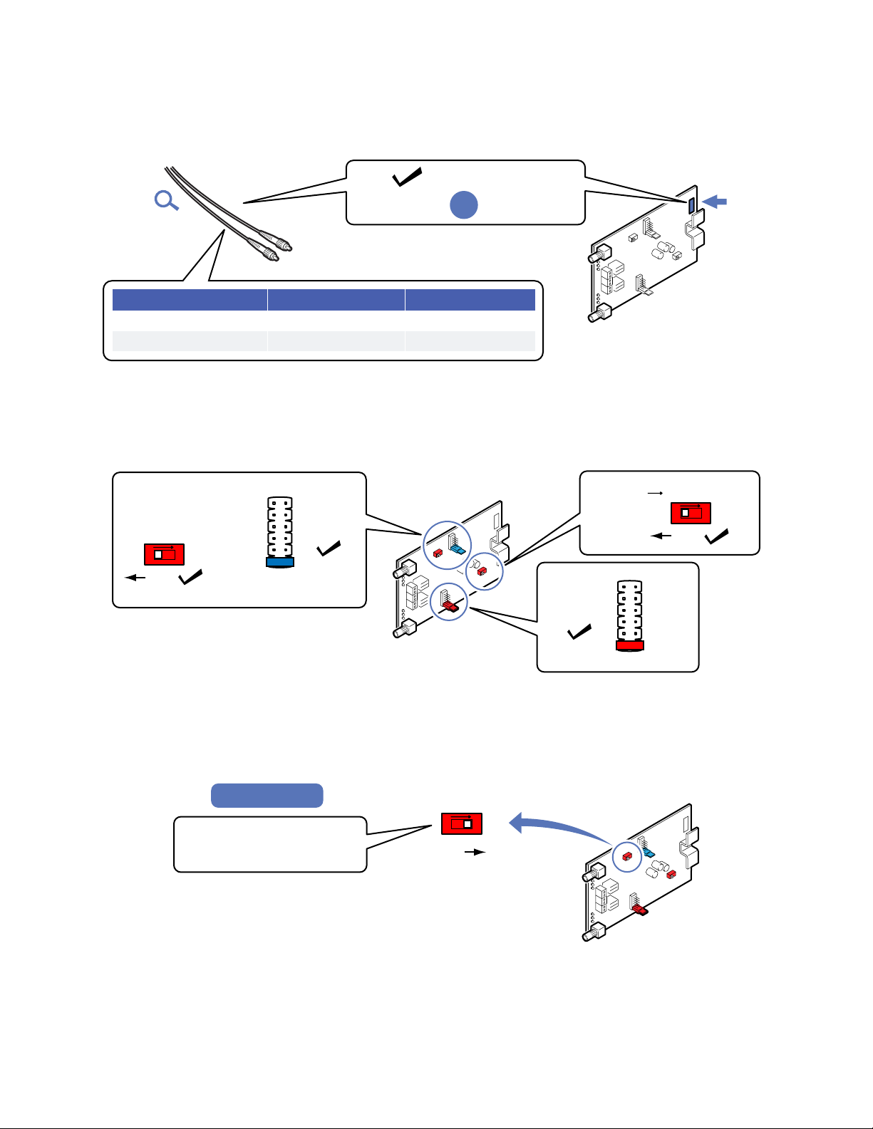
2.4 Verify matching card and fiber modes
Fiber mode and card mode must be the same.
!
2.5 Set default T1 card settings
Settings are the same for both CO and Sub cards.
!
2.6 For extended distance multimode systems
!
Fiber Type
Color
Identifier
Single Mode
Yellow
9/125
Multimode
Orange
62.5/125
Multimode
Same Fiber Mode:
Fiber Optic
Cables
T-1 Fiber Optic
Link Card
Mode
Label
Single Mode
OR
1
2
3
4
5
6
LOSS
SELECT
(Blue
Jumper)
(Red)
(Red)
(Red
Jumper)
1
2
3
4
5
6
GAIN
ON
OFF
ONOFF
FIBER SIGNAL SW2
ON
OFF
ONOFF
FIBER LOSS
<4dB>
OFF
Position 1
OFF
T-1
Fiber Optic
Link Card Position 1
ON
OFF
ONOFF
FIBER LOSS
<4dB>
Set FIBER LOSS switch to ON
for fiber over 4,000 feet
(loss of 4dB)
Multimode Only
ON
Before Installing10

Installing card housing
3.1 Mount housing in equipment rack or attach to backboard.
Leave room for the door to open, and enough slack in wiring and fiber to allow for card access.
Installing into card housing
4.1 Note card orientation in housing during installation
Handle card by edges. Install in slot 1 or next available card slot. Install card into housing before connecting
copper wiring or fiber cable.
!
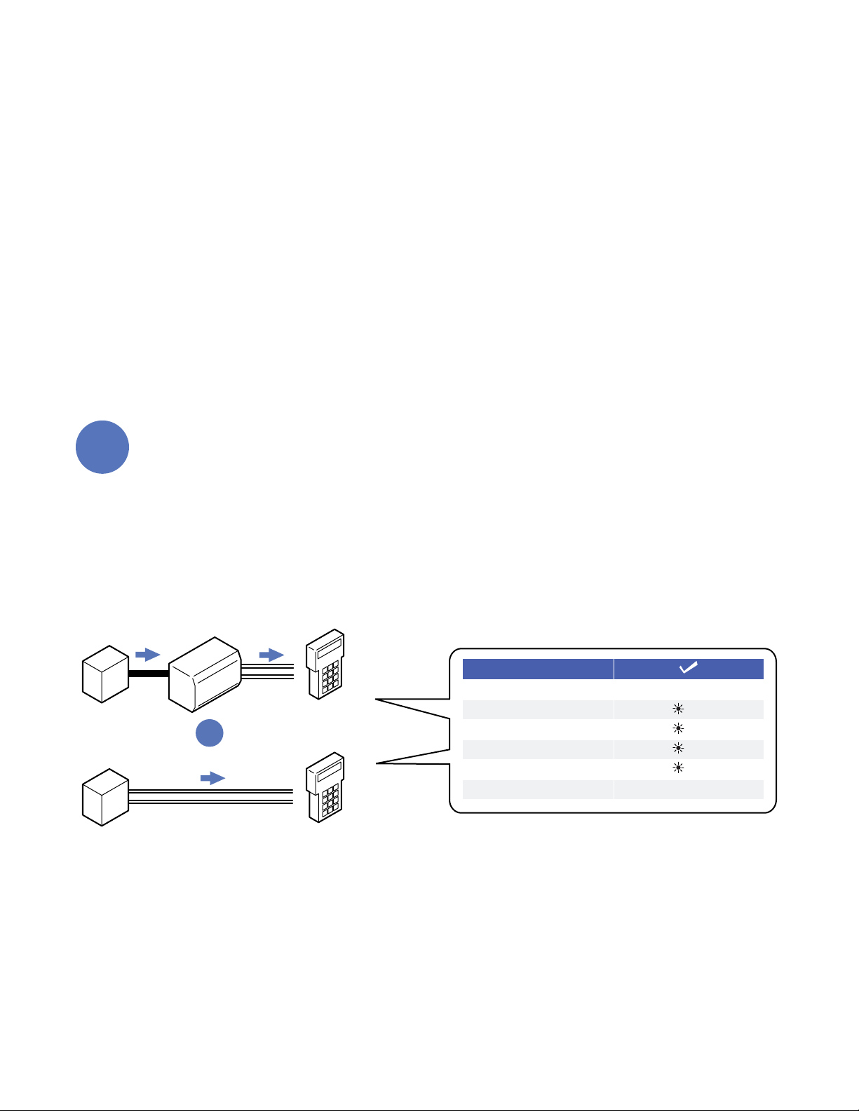
Required test equipment
5.1 You will need a T1 analyzer such as a T-BERD and a multimeter
Be familiar with the test settings. Some analyzers have line power and multimeter capability. For installation where
no T-1 signal is available, the analyzer must be capable of generating a quasi-random T-1 signal.
!#
Can generate a quasi-random T1 signal
OK
OK
BATT
T1 Analyzer
OK
OK
BATT
Multimeter
Before Installing 11
3.
4.
5.

5.2 Required power sources if installing before T-1 service is available at the site
You will need to power the system to test it. Use a separate power source for powering the CO and Sub side card.
A battery may be used.
!
Copper wiring requirements
6.1 Copper wiring to the T1 cards
The connectors on the T-1 cards are designed for specific wire sizes and mechanical connections at the terminals.
•Use 22~24AWG solid copper wire#
•Stripping length: 8mm#
•Connector tightening torque: 0.5~0.6 Nm. Do not over-tighten screw down wire terminals.#
'
+
–
24 - 56VDC
AC Volts
Power SourcePower Source
24 - 56VDC
AC Volts
OK
BATT
+
–
Multimeter Multimeter
OK
BATT
Sub Side
CO Side
Use 22~24AWG solid wire for power supply connections.
Refer to the power supply connection and use information for fuse or circuit breaker requirements. Use caution
when handling copper wiring. Power connections may carry high voltages.
Fuses must be installed within a finger safe housing to prevent electric shock from accidental contact or during
fuse replacement.
Use 22~24AWG
solid copper wire
only.
Wire Stripping 8mm
0.3 in.
T1 wires
T1 card
0.5~0.6Nm max.
Screwdriver
Screw down
terminals
Before Installing12
6.

Verify your installation environment
7.1 Typical T1 application environments
Fiber optic cable needs to be installed at the location prior to connecting T1 Fiber Link Card system.
!
Central
Office /
Switch
HDSL/T1 NIU
with 60mA Span
Through Power
Line Powered Line Powered
CO Card Sub Card
CFJ
CFJ
Local Powered
24-56VDC
Power
Supply
CPE
4-Wire
Copper T1
HDSL/T1 Span
Fiber Optic
Cable
4-Wire
Copper T1
RXTX
RX TX
Central
Office /
Switch
Line Powered
CO Card Sub Card
Local Powered Local Powered
24-56VDC
Power
Supply
T1 NIU
Smartjack
4-Wire Copper
T1 Span
Fiber Optic
Cable
4-Wire
Copper T1
RXTX
RX TX
Before Installing 13
7.
Installation when T-1!
service is available
Also see Installation prior to T1 service availability on page 23.
!Connect CO card
1.1 Verify acceptable T1 signal
Repair the T1 lines if service is not acceptable. Check for NIU Compatibility in the Troubleshooting section.
!
1
Test
PEAK TO PEAK VOLTAGE
0.19V ~ 9.0V
T1 PULSES
PATTERN SYNC
FRAME SYNC
BZ8S or AMI
BIT ERRORS
NONE
OK
OK
OK
OK
NIU
T1
Central
Office
T1
Analyzer
T1
Central
Office
T1
Analyzer
OR
Installing when T1 service is present Installation14

1.2 Connect T-1 pairs to card terminals
Install into housing for connecting and testing. Refer to Installing into card housing on page 9.!
All LEDs will be ON for approximately 5 seconds after span power is first applied.
!!
Pair #
First wire
Second wire
1
White
Blue
2
Orange
3
Green
4
Brown
5
Gray
6
Red
Blue
7
Orange
8
Green
9
Brown
10
Gray
11
Black
Blue
12
Orange
13
Green
14
Brown
15
Gray
16
Yellow
Blue
17
Orange
18
Green
19
Brown
20
Slate
21
Violet
Blue
22
Orange
23
Green
24
Brown
25
Gray
Standard 25-Pair Color Code
OUTPUT 24-56VDC
AUX. P.S. INPUT
FIBR RCV XMIT LIMIT PWRALARM
RX TX
Connect
TX pair
Connect
RX pair
RED ALARM
LED = ON
Will go off
once system
is connected.
Use 22~24AWG
solid copper wire
only.
T1 wires
Gently tug after securing
into terminal to ensure
wire isn’t damaged.
Installation Installing when T1 service is present 15

1.3 Connection using optional RJ connector
RJ connector may be pre-installed or obtained separately.
!
1.4 Verify power at the T1 card
Test for Span power.
!
Pin 1
Pin 8
Use jack marked CO
Optional RJ-45 jack
CO
CO
CO
CO
CO
RX pair, pins 1,2
TX pair, pins 4, 5
OUTPUT 24-56VDC
AUX. P.S. INPUT
FIBR RCV XMIT LIMIT PWRALARM
RX TX
PWR LED indicates that
power is OK
60mA span power
22V minimum
Multimeter
BLU = ON
Installing when T1 service is present Installation16

1.5 Connect local power if Span power is not present
All LEDs will be ON for approximately 5 seconds after power is first applied.
!
Auxilliary power wires
Gently tug after securing
intoterminal to ensure
wire isn’t damaged.
OUTPUT 24-56VDC
AUX. P.S. INPUT
FIBR RCV XMIT LIMIT PWRALARM
RX TX
PWR LED indicates that
power is OK
Multimeter
BLU = ON
Auxilliary Power Terminal
24-56VDC Local Power
Not polarity sensitive
24-56VDC
Use 22~24AWG
solid copper wire only.
Refer to the power supply connection and use information for fuse or circuit breaker requirements. Use caution
when handling copper wiring. Power connections may carry high voltages.
Fuses must be installed within a finger safe housing to prevent electric shock from accidental contact or during
fuse replacement.
Installation Installing when T1 service is present 17

!Set CO card gain
2.1 Set gain using red gain GAIN jumper
Set gain while T1 signal is present. Refer to the Specifications section for input signal requirements.
!
2
The blue LOSS SELECT jumper must remain at position 1.
1
2
3
4
5
6
GAIN
Move jumper to
next higher position.
Repeat until orange
LIMIT LED comes ON,
then stop.
OUTPUT 24-56VDC
AUX. P.S. INPUT
FIBR RCV XMIT LIMIT PWRALARM
RX TX
ORG LED is ON when
copper signal is too high
RED
Jumper
1
2
3
4
5
6
GAIN
Move jumper
back one position.
Orange LIMIT LED
will go OFF.
Green XMIT LED
will stay ON.
Note final
jumper position
OUTPUT 24-56VDC
AUX. P.S. INPUT
FIBR RCV XMIT LIMIT PWRALARM
RX TX
Amber LED turns OFF.
Gain is set at proper level.
1
2
GRN LED is ON when copper
signal is above minimum level
Each jumper position is equivalent to approximately 6dB of gain. Setting the CO gain at the correct level ensures
that the fiber optic transceiver system operates within normal levels.
The gain on the CO card is offset by setting a matching attenuation using the loss select jumper on the Sub card.
Installing when T1 service is present Installation18

!Verify CO card operation
3.1 Check CO card operation
Perform loopback test using fiber jumper
!
!Connect CO fiber cables
4.1 Connect fiber optic cable
Move on to Sub side after verifying LEDs.
!
3
Attach Test Kit
Simplex
Fiber Jumper OUTPUT 24-56VDC
AUX. P.S. INPUT
FIBR RCV XMIT LIMIT PWRALARM
RX TX
OFFRED
ALARM RCV XMIT PWR
ONGRN GRN BLUON ON
After using, store
fiber jumper with test kit
at convient site location.
• Do not discard fiber caps.
• Replace caps after use.
If both GREEN LEDs are not ON,
verify T1 signal, power and connections
4
OUTPUT 24-56VDC
AUX. P.S. INPUT
FIBR RCV XMIT LIMIT PWRALARM
RX TX
Fiber RX
Note fiber numbers
for RX and TX
Loose loops or use
fiber routing clips
Fiber TX
GRN ONRED ON BLU ON
Fiber Optic Cable
to SUB side
Card Housing
Push
“Click”
Installation Installing when T1 service is present 19

!Connect Sub card
5.1 Connect fiber cables
Flip or roll the fiber cables
!
!Connect loopback jumpers and power
6.1 Connect copper loopback jumpers
When using wire terminals.
'
5
TX fiber
connector
RX fiber
from CO side
RX TX
Flip fiber
connections
TX fiber
from CO side
RX fiber
connector
Do not touch fiber connector
ends which could cause
contamination and lower
signal performance.
Card partially
out of slot
during installation
Fiber Optic Cable
from CO side
Card Housing
6
Installing when T1 service is present Installation20
Other manuals for 16 Channel T1 Over Ethernet Multiplexer...
2
Table of contents
Other RLH Industries Media Converter manuals

RLH Industries
RLH Industries SED-03-2 User manual

RLH Industries
RLH Industries RLH 10 User manual

RLH Industries
RLH Industries 1+1 PORT SLIMLINE User manual

RLH Industries
RLH Industries 16 Channel T1 Over Ethernet Multiplexer... User manual

RLH Industries
RLH Industries Fiber Optic Link User manual

RLH Industries
RLH Industries 2 Channel 4 Wire Datawith E&M and I/O User manual


