manuals.online logo
Brands
  1. Home
  2. •
  3. Brands
  4. •
  5. GSS
  6. •
  7. Media Converter
  8. •
  9. GSS HMPT 1000 C User manual

GSS HMPT 1000 C User manual

Other GSS Media Converter manuals

GSS PEDQ 3005 QMX User manual

GSS

GSS PEDQ 3005 QMX User manual

GSS PTDT 1000 User manual

GSS

GSS PTDT 1000 User manual

GSS HDE 400 User manual

GSS

GSS HDE 400 User manual

GSS HDMT 1000 SPTS User manual

GSS

GSS HDMT 1000 SPTS User manual

GSS PHDQ 6100 CI TPS User manual

GSS

GSS PHDQ 6100 CI TPS User manual

GSS SOQ 100 User manual

GSS

GSS SOQ 100 User manual

GSS HDE 166 User manual

GSS

GSS HDE 166 User manual

GSS HDTV 1000 MPTS User manual

GSS

GSS HDTV 1000 MPTS User manual

GSS HRC 300 AV User manual

GSS

GSS HRC 300 AV User manual

GSS PTIS User manual

GSS

GSS PTIS User manual

GSS HRC 300 AV User manual

GSS

GSS HRC 300 AV User manual

GSS PTIM 1000 User manual

GSS

GSS PTIM 1000 User manual

GSS STC 100 User manual

GSS

GSS STC 100 User manual

GSS PAIS 5100 User manual

GSS

GSS PAIS 5100 User manual

GSS PTIS 1000 User manual

GSS

GSS PTIS 1000 User manual

GSS HDMC 1000 SPTS User manual

GSS

GSS HDMC 1000 SPTS User manual

GSS PCIM 1000 User manual

GSS

GSS PCIM 1000 User manual

GSS PMDQ 1000 User manual

GSS

GSS PMDQ 1000 User manual

GSS STI 1916 CT User manual

GSS

GSS STI 1916 CT User manual

GSS PHDQ 1000 ASI DF User manual

GSS

GSS PHDQ 1000 ASI DF User manual

GSS GSS.mux SMCIP 401 User manual

GSS

GSS GSS.mux SMCIP 401 User manual

GSS Professional PADE 7006 User manual

GSS

GSS Professional PADE 7006 User manual

GSS SOQD 104 User manual

GSS

GSS SOQD 104 User manual

GSS PHIS 1000 S User manual

GSS

GSS PHIS 1000 S User manual

Popular Media Converter manuals by other brands

TR-Electronic CMS582M-4096/4096 IOL DMS 14H7 KRF Assembly instructions

TR-Electronic

TR-Electronic CMS582M-4096/4096 IOL DMS 14H7 KRF Assembly instructions

Korenix JetCon 2301S user manual

Korenix

Korenix JetCon 2301S user manual

StarTech.com ET91000LCOAM manual

StarTech.com

StarTech.com ET91000LCOAM manual

Alesis AI-3 Reference manual

Alesis

Alesis AI-3 Reference manual

Caton Vpro 5100 user guide

Caton

Caton Vpro 5100 user guide

Cypress CSC-5500 Operation manual

Cypress

Cypress CSC-5500 Operation manual

H&B TX-100 Installation and instruction manual

H&B

H&B TX-100 Installation and instruction manual

Bolin Technology D Series user manual

Bolin Technology

Bolin Technology D Series user manual

IFM Electronic Efector 400 RN30 Series Device manual

IFM Electronic

IFM Electronic Efector 400 RN30 Series Device manual

GRASS VALLEY KUDOSPRO ULC2000 user manual

GRASS VALLEY

GRASS VALLEY KUDOSPRO ULC2000 user manual

Linear Technology DC1523A Demo Manual

Linear Technology

Linear Technology DC1523A Demo Manual

Lika ROTAPULS I28 Series quick start guide

Lika

Lika ROTAPULS I28 Series quick start guide

Weidmuller IE-MC-VL Series Hardware installation guide

Weidmuller

Weidmuller IE-MC-VL Series Hardware installation guide

Optical Systems Design OSD2139 Series Operator's manual

Optical Systems Design

Optical Systems Design OSD2139 Series Operator's manual

Tema Telecomunicazioni AD615/S product manual

Tema Telecomunicazioni

Tema Telecomunicazioni AD615/S product manual

KTI Networks KGC-352 Series installation guide

KTI Networks

KTI Networks KGC-352 Series installation guide

Gira 0588 Series operating instructions

Gira

Gira 0588 Series operating instructions

Lika SFA-5000-FD user guide

Lika

Lika SFA-5000-FD user guide

manuals.online logo
manuals.online logoBrands
  • About & Mission
  • Contact us
  • Privacy Policy
  • Terms and Conditions

Copyright 2025 Manuals.Online. All Rights Reserved.

Assembly Instruction
HMPT 1000 C
- 2 - HMPT 1000 C
Contents
1 Safety regulations and notes ........................................................................4
2 General information ....................................................................................5
2.1 Packing contents ............................................................................5
2.2 Meaning of the symbols used ..........................................................5
2.3 Technical data ...............................................................................5
2.4 Description ...................................................................................6
Input signal path "INROUTE" ..........................................................7
Menu setting "A=1 B=2" .........................................................7
Menu setting "A+B=1 2=OFF" .................................................7
Output signal path "OUTROUTE" ....................................................8
Menu setting "1=>MA 2=>MB" ...............................................8
Menu setting "1=>ASI MA=OFF" .............................................8
Menu setting "2=>ASI MB=OFF" .............................................8
General ........................................................................................9
2.5 Software query............................................................................10
2.6 How the TPS module works ...........................................................10
Station filter ................................................................................10
Stuffing.......................................................................................10
Changing the NIT ........................................................................10
Changing the operator ID (CAT) ...................................................10
2.7 Explanation of the term "symbol rate" ............................................11
3 Assembly ..................................................................................................12
3.1 Installing the cassette....................................................................12
3.2 EMC regulations ..........................................................................13
3.3 Cassette overview........................................................................14
3.4 Connecting the cassette ................................................................14
3.5 Retrofitting a CA module ..............................................................15
4 The control panel at a glance .....................................................................16
4.1 Menu items .................................................................................16
4.2 Control panel ..............................................................................17
5 Programming ............................................................................................17
5.1 Preparation .................................................................................17
5.2 Programming procedure ...............................................................18
5.3 Programming the cassette ............................................................22
Selecting the cassette, displaying the software version ......................22
Ethernet parameters .....................................................................23
IP address of the cassette ..............................................................23
Address range ............................................................................24
- 3 - HMPT 1000 C
Address of the gateway ................................................................24
UDP port ....................................................................................24
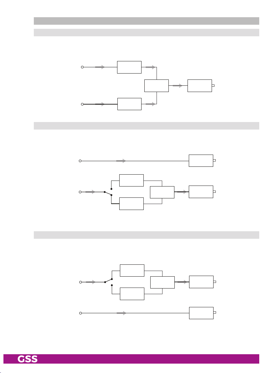
Input signal path ..........................................................................25
Output signal path .......................................................................25
ASI transfer rate ..........................................................................26
ASI options................................................................................... 26
Channel strip ..............................................................................27
Selecting channel / frequency setting .............................................27
Output frequency, Output channel, Modulator .................................28
Output levels of the channel strips ..................................................29
Input data stream .........................................................................29
IP reception, Transmission protocol, Port number .............................30
IP address of the input transport stream ..........................................31
Station filter ................................................................................31
"INROUTE" menu setting "A = 1 B = 2" ..................................32
Test the status of the individual services: ....................................33
"INROUTE" menu setting "A+B = 1 2 = OFF" ..........................33
QAM modulation
,
Inverting the user signal .....................................34
Setting the QAM modulation ....................................................34
Inverting the user signal ...........................................................34
Output symbol range ...................................................................35
Substitute signal in the case of an incorrect input signal ...................36
Transport stream / ORGNET-ID .....................................................36
Network Information Table (NIT) ....................................................37
Network/operator identification ....................................................38
Deleting a PID .............................................................................39
Renaming a PID...........................................................................39
Factory reset ...............................................................................40
Saving settings ............................................................................40
Tuner settings ..............................................................................41
LNB oscillator frequency ..........................................................41
Input symbol rate, DVB mode ...................................................41
Input frequency ......................................................................42
Testing the signal to noise ratio .................................................43
Operation with a CA module ........................................................44
PID monitoring .......................................................................44
CA module ............................................................................44
Descrambling services .............................................................46
6 Final procedures ........................................................................................47
7 Channel and frequency tables ....................................................................48
- 4 - HMPT 1000 C
1 safety regulations and notes
• Assembly, installation and servicing should be carried out by authorised
electricians.
• Switch off the operating voltage of the system before beginning with assem-
bly or service work or pull out the mains plug.
• Do not perform installation and service work during thunderstorms.
• Install the system so it will not be able to vibrate…
- in a dust-free, dry environment
- in such a manner that it is protected from moisture, fumes, splashing wa-
ter and dampness
- somewhere protected from direct sunlight
- not within the immediate vicinity of heat sources
- in an ambient temperature of 0 °C to +50 °C. In case of the formation of
condensation wait until the system is completely dried.
• Ensure that the head-end station is adequately ventilated. Do not cover the
ventilation slots.
• Beware of short circuits
• No liability is accepted for any damage caused by faulty connections or
inappropriate handling.
• Observe the relevant standards, regulations and guidelines on the installa-
tion and operation of antenna systems.
• The standards EN/DIN EN 50083 resp. IEC/EN/DIN EN 60728 must be
observed.
• For further information please read the assembly instructions for the head-
end station used.
• Test the software versions of the head-end station and the cassette and
update them if necessary. The current software versions can be found at
"www.mygss.eu".
Take action to prevent static discharge when working on the device!
Electronic devices should never be disposed of in the household rubbish. In
accordance with directive 2002/96/EC of the European Parliament and the
European Council from January 27, 2003 which addresses old electronic and
electrical devices, such devices must be disposed of at a designated collection
facility. At the end of its service life, please take your device to one of these
public collection facilities for proper disposal.
- 5 - HMPT 1000 C
2 general information
2.1 PaCking Contents
1 Cassette HMPT 1000 C
1 RF cable
1 Brief assembly instructions
2.2 meaning of the symbols used
Important note
—> General note
• Performing works
2.3 teChniCal data
The devices meet the following EU directives:
2011/65/EU, 2014/30/EU, 2014/35/EU
The product fulfils the guidelines and standards for CE labelling (page 49).
Unless otherwise noted all values are specified as "typical".
RF input
Frequency range: ....................................................... 925 … 2150 MHz
Level range: ............................................................ 60 dBμV … 80 dBμV
Return loss: ..................................................................................> 8 dB
DVB-S modes: ............................................DVB-S 1/2 , 2/3 , 3/4 , 5/6 , 7/8
DVB-S2 modes: ...................QPSK 1/2 , 3/5 , 2/3 , 3/4 , 4/5 , 5/6 , 8/9 , 9/10
8PSK 3/5 , 2/3 , 3/4 , 5/6 , 8/9 , 9/10
Symbol rate DVB-S: .......................................... QPSK: 2 … 45 MSymb/s
Symbol rate DVB-S2: ........................................ QPSK: 10 … 30 MSymb/s
8PSK: 10 … 31 MSymb/s
RF output
Channels: ............................................................................ S21 … C69
Frequency range: ............................................. 42.0 MHz … 860.0 MHz
Output level: ..................................................................... max. 96 dBμV
Output impedance: .........................................................................75 Ω
- 6 - HMPT 1000 C
LAN interface
Standard: .............................................................................100-BASE-T
Data rate: ............................................................................... ≤ 80 MBit
Protocols: .......................................................... UDP (User Data Protocol),
RTP (Real-Time Transport Protocol)
ASI interface
Standard: .....................................................................DIN EN 50083-9
Format: ..............................................................MPEG ISO IEC 13818-1
User data rate: .................................................................2 … 90 Mbit/s
Level (input / output): ..................................................... 800 mVPP ± 10%
Return loss (input):...............................................> 17 dB (5 … 270 MHz)
Connections
SAT input: ............................................................................... 1 F socket
RF output: ............................................................................1 IEC socket
ASI output: ................................................................1 BNC socket, 75 Ω
Connection strip (10-pin): ..................for supply voltages and control circuits
RS 232 socket: ..................................... serial interface for software update
Conditional access:.......................1 (several channels can be descrambled)
2.4 desCriPtion
The cassette is a
"MPTS / QAM"
-converter, which converts services
(stations)
modulated according to DVB-S /
DVB-S2
standard and the data stream fed via
the LAN interface into one or two QAM-modulated cable signals dependent on
the input and output signal paths.
The
cassette
has one SAT IF input and one
RF output. Additionally it is equipped with a LAN interface and an ASI output
(ASI – Asynchronous Serial Interface acc. DIN EN 50083-9).
The transport stream fed via the LAN socket can be inserted into the transport
stream of the receiving stage via the TPS module.
T
he signal path is set in the
menu items input signal path
"INROUTE" and output signal path "OUTROUTE"
.
- 7 - HMPT 1000 C
inPut signal Path "inroute"
menu setting "a=1 b=2"
The transport streams of the receiving stage channel strip "A" and of the LAN
input channel strip "A" generate optionally the transport stream 1. The trans-
port stream of the LAN input channel strip "B" generate the transport stream 2.
TPS
Channel strip "B"
LAN
interface
SAT IF
input ”A“
LAN
interface
Receiving stage
Channel strip "A"
Channel strip "A"
CA module
Transport stream 1
Transport stream 2
menu setting "a+b=1 2=off"
The transport streams of the receiving stage channel strip "A" and optionally
of the LAN input channel strip "A" generate in conjunction with the transport
stream of the LAN input channel strip "B" the transport stream 1.
The
transport
stream 2 is switched off.
TPS
LAN
interface
SAT IF
input ”A“
LAN
interface
Receiving stage
Channel strip "A"
Channel strip "A"
CA module
Transport stream 1
Transport stream 2
Channel strip "B"
- 8 - HMPT 1000 C
outPut signal Path "outroute"
menu setting "1=>ma 2=>mb"
Transport stream 1 is made available via modulator "A", transport stream 2
via modulator "B".
Combiner
Modulator
"A"
Modulator
"B"
Transport stream 1
Transport stream 2
HF output
menu setting "1=>asi ma=off"
Transport stream 1 is made available via the ASI output, transport stream 2 via
modulator "B". The signal path via modulator "A" (MA) is switched off.
Modulator
"B"
Modulator
"A"
Combiner
Transport stream 2
ASI output
HF output
Transport stream 1
menu setting "2=>asi mb=off"
Transport stream 1 is made available via modulator "A", transport stream 2
via the ASI output. The signal path via modulator "B" (MB) is switched off.
Modulator
"B"
Modulator
"A"
Combiner
Transport stream 1 HF output
ASI output
Transport stream 2
- 9 - HMPT 1000 C
general
The cassette is equipped with two channel strips ("A" and "B"). The "A" chan-
nel strip has a digital SAT tuner and can process both the transport stream fed
in via the LAN interface and the transport stream from the SAT tuner.
Using an
appropriate CA module, encoded services coming from the SAT tuner can be
decoded in channel strip"A". The "B" channel strip only processes the trans-
port stream fed in via the LAN interface. The transport streams are directed to
the ASI output or the output converter depending on the set output signal route
"OUTROUTE" via the digital signal processing levels. The RF output signals are
sent through the RF output on the cassette to the output collector. The common
output level of the channel strips can be set in the output collector on the head-
end station.
An LED in channel strip "A" provides an indication of the signal quality for
the SAT IF input signal and shows whether the modulator of the channel strip
is activated (LED lights up) or deactivated. The quality of the transport stream
being received is also shown in the display ("CN…").
The integrated TPS module (Transport Stream Processing) processes the data
from the transport streams.
The channel strips are indicated in the head-end station display with "Bx …A"
and "Bx …B". The control of the cassette takes place via the control unit of the
head-end station.
When the head-end station is switched on, the two-line LC display shows the
software version of the control unit.
To operate this cassette the software version of the control unit must be "V 45"
or higher. You can find the current operating software for the control unit and
the cassette, the software "BE-Flash" and the current assembly instructions on
the website "www.mygss.eu".
The cassette is intended for use in the
STANDARD LINE
head-end stations.
- 10 - HMPT 1000 C
2.5 soft ware query
Control unit
If necessary, you can activate the indication of the software version of the
control unit manually:
• Press any two keys on the control unit of the head-end station simultaneously
until the display goes dark and the software version, e.g. "V 45" appears.
Cassette
After activating the cassette the software version of the cassette is displayed
(see.page 22).
2.6 how the tPs module works
After decoding QPSK- or 8PSK-modulated signals, the demodulated data
stream can be accessed via the integrated TPS module. This data stream,
also called transport stream, contains several stations in all their components
(video, audio, data and service information), which can be changed using the
TPS module.
station filter
Individual stations can be deleted. This reduces the data rate and, conse-
quently, the output symbol rate required. Additionally stations of the different
transport streams can be assembled to a new transport stream.
stuffing
The transport stream is padded using what is known as zero data. This ensures
a steady and constant output symbol rate.
Changing the nit
The transport stream contains data in the form of tables which the receiv-
ers evaluate and require for convenient use. The TPS module can adjust the
"Network Information Table" (NIT) to accommodate the new station data. The
"NIT" contains data which is required by the set-top box for the automatic
search feature.
Changing the oPer ator id (Cat)
Some network operators transmit an operator ID in the data stream (e.g.
visAvision). By changing the CAT the operator ID can be adjusted to the de-
mands.