RLS Wacon Aqua Inform Sycon 2501 Fe User manual

Sycon 2501 Fe
On-line Analysis
of the Iron Content in Water
V24.02.2015
US E R MA N U A L

INTRODUCTION
PAGE 3
INTRODUCTION
We appreciate your purchase of a Limit Analyser type Sycon 2501 Fe for the on-
line monitoring of the iron content of water.
The Limit Analyser is part of a water treatment plant. Distribution of this manual is
intended for the manufacturer and the owner of this plant.
This user’s manual covers instructions for the use of your Limit Analyser. Please
read through this manual and understand the contents before using the system.
We recommend that the manual be kept nearby for reference when operating the
Limit Analyser system.
Operate the system only in accordance with the instructions given in this manual.
Under no circumstances whatsoever will we be liable for damages arising from the
user’s failure to follow the instructions given in this manual.
•Some details of the instructions contained in this manual may be different
from the actual system purchased. The instructions are also subject to
change without prior notice.
The Limit Analyser based on the Sycon 2501 series is an on-line analysis
system. It can automatically monitor iron leakage in water treatment plants
and issue an iron leakage alarm.
It is not a system that remedies iron leakage itself.
WARNING

PAGE 4
TABLE OF CONTENT
TABLE OF CONTENTS
PAGE
SUMMARY SYCON 2501 SERIES
6
CHAPTER 1
SAFETY WARNINGS /PRECAUTIONS /SYMBOLS USED
7
CHAPTER 2
SPECIFICATION AND OVERVIEW
2.1 SPECIFICATION AND INTENDED USE
→GENERAL SPECIFICATION
→TECHNICAL DATA
→MONITORING CAPABILITIES
→WATER INLET AND OUTLET
→AVAILABLE REAGENTS
→ACCESSORIES
2.2 OVERVIEW AND CONFIGURATION
2.3 DISPLAY AND CONTROL BUTTONS
2.4 SPARE PART LIST
2.5 OPERATION PRINCIPLE
2.6 FUNCTIONS
11
11
13
14
15
16
17
CHAPTER 3
INSTALLATION AND COMMISSIONING
3.1 INSTALLATION REQUIREMENTS
3.2 INSTRUCTIONS FOR INSTALLATION
3.3 MOUNTING IN 4STEPS
→TERMINAL CONNECTION TABLE
→INSTRUCTION FOR WIRING AND CONNECTION
→MOUNTING DIMENSIONS
3.4 CONNECTING RELAY-OUTPUT
3.5 CONNECTING DIGITAL INPUTS
19
19
19
20
25
26
CHAPTER 4
OPERATION AND USE
4.1 SUMMARY OF SYCON 2501 SYSTEM
4.2 BEFORE INITIAL OPERATION
4.3 PROGRAMME SWITCHES
4.4 SETTING THE PROGRAMME SWITCHES
→FLUSH TIME
→DELAY INTERVALS
→ANALYSIS INTERVALS
→ANALYSIS REPETITION
→RELAY FUNCTION
→MEASUREMENT-PARAMETERS
4.5 COMMISSIONING IN 5STEPS
4.6 OPERATION OF THE UNIT
→AUTOMATIC OPERATION
→MANUAL OPERATION
27
27
28
29
30
36
37

TABLE OF CONTENT
PAGE 5
CHAPTER 5
MAINTENANCE AND SERVICE
→CHANGING PERISTALTIC DOSING PUMP
→CLEANING OF THE MEASURING-CHAMBER
→CHANGING WORN PARTS
→CHANGING REAGENT BOTTLE
→CHANGING SPARE PARTS
41
CHAPTER 6
DIAGNOSTIC FUNCTION
TEST OF →LEDS
→CONTROL-BUTTON
→DIP SWITCH
→POTENTIOMETER
→RELAY 1+2
→SOLENOID VALVE
→ACTUATOR LED
→DOSING PUMP
→MAGNETIC AGITATOR
→‘IN’CONTACT
→ZERO-TRANSMISSION
→COLOUR DETECTION
48

PAGE 6
SUMMARY
SUMMARY SYCON 2501 SERIES
With the Limit Analyser, RLS Wacon offers a very compact and easily operated water
analyser for automatic on-line monitoring of water treatment plants. The system
controls selectable limit values according to the colorimetric principle. A broad range
of functions guarantee reliable field-operation. Units can be supplied in standard as
well as tailor-made housings
Application:
→Limit monitoring (below and above limit detection)
→suitable for operation without permanent supervision (BOB)
Order numbers
Limit Analyser
SYCON 2501 Fe
30-010321
Standard enclosure
33-099005
Reagents
Fe-LRS
0.03 –0.6 mg Fe/l
32-080320
Fe-HRS
0.3 –6.0 mg Fe/l
32-080330
CHAPTER 1
SAFETY INSTRUCTIONS
PAGE 7
CHAPTER 1 SAFETY WARNINGS AND PRECAUTIONS
This Chapter explains the dangers, precautionary signs and notes that apply to
the handling, installation, wiring and maintenance of the SYCON 2500 series Limit
Analyser. These instructions are not a substitute for vocational training.
This manual describes the installation and operation of the on-line analyser of
type Limit Analyser Fe based on SYCON 2501 series. Installation and
commissioning must only be performed by qualified personnel.
Operate the system only in accordance with the instructions given in this manual.
In particular, the system has to be protected against humidity and moisture. Avoid
direct contact with splash or condense water. The device may only be used for
the specified purpose. When installing and operating the equipment, the relevant
standards (e.g. EN, DIN, VDE, UVV) and applicable local regulations must be
complied with.
The analyser is used to monitor the limits of the iron content in process water.
Proper operation can only be guaranteed with the manufacturer's recommended
reagents and spare parts.
Changes to the electrical connections and the programming should only be
performed by a qualified person.
If it is necessary to connect cables for the sensors they should be kept as short
as possible and not run together with power cables. The vicinity of a strong
electromagnetic field may lead to deviations of evaluation and measurement
results. In such cases, appropriate measures must be taken to suppress
interferences. EMC-directives are especially applicable.
When working with this manual, it is recommended to have access to the
operational instrument in order to understand the functions described
immediately. Read the chapters in the order given.
If you have questions regarding the operation of the instrument, or when
problems occur, please contact us or one of our distributors. Try to locate
problems as accurately as possible. Also describe what actions you have taken
and which conditions lead to the problem. We will then be in a better position to
help you.
Labour protection
Rules for
accident
prevention
of
government
and industrial
safety
organisations
Operating Manual

PAGE 8
SAFETY INSTRUCTIONS
CHAPTER 1
Safety instructions and symbols used
In this manual you will find specific safety instructions to indicate the unavoidable
residual risks when operating the unit. These residual risks imply dangers to
●People
●Product / Plant / Machinery
●Environment
The symbols used in the instructions draw attention in particular to the safety
instructions!
The main objective of the safety precautions is to prevent personal injury.
The symbol used in each case cannot replace the text of a safety warning.
Therefore, the text must always be read completely.
This symbol indicates a potential danger to persons.
→mortal danger
→risk of injury
●A safety notice with warning triangle DANGER points out that risks to plant,
machinery, materials, environment and people are not excluded
This symbol indicates a potential danger to product, plant and machinery
●A safety notice with warning triangle WARNING points out that risks to
plant, machinery, materials and/or environment are not excluded.
Danger to persons is not necessarily to be expected.
This symbol points to hydraulic and pneumatic systems and indicates
pressurised systems.
This symbol indicates electric and electronic systems.
This symbol indicates no safety information, but information to improve
understanding of the plant or machine processes.
DANGER
WARNING
PRESSURE
ELECTRICITY
NOTE

CHAPTER 1
SAFETY INSTRUCTIONS
PAGE 9
Work on hydraulic and pneumatic equipment
●Maintenance and repair of hydraulic and pneumatic equipment should be
carried out by specially trained personnel!
●Before all maintenance and repair work, the pneumatic and hydraulic
equipment of the system / machine must be depressurised!
●During preventive maintenance, pipes should be changed regularly, even
if there is no visible damage (Please note the information provided by the
manufacturer).
●Before starting up after maintenance or repair work,
→Check the screw connections for a tight fit and that push-in fittings are
secured.
→Ensure that the container lid, screens or filters are re-installed in the
correct order.
●After completion of the maintenance and repair services, and before the
resumption of operation, make sure that…
→…all the materials, tools and other equipment required for the execution of
maintenance or repair work are removed from the work area!
→…any leaked fluids are removed!
→…all safety devices of the system work properly again!
Transportation
Use appropriate equipment to transport the system to prevent damage during
transport.
●Transport equipment carefully and do not throw it!
●Choose a cool and dry storage location.
●Pay attention to the permitted ambient temperatures!
●Check the entire delivery immediately upon receipt for completeness and
shipping damage
●Devices are packed in a transport-safe packaging. Nevertheless, damage
could occur during transit. Please tell the transport company and the
manufacturer in writing IMMEDIATELY - no later than eight days after
receiving the goods - of the details of the damage. In this case, you must
keep the instrument and the packaging for inspection for the further
processing of the complaint.
WARNING
PRESSURE
NOTE
PAGE 10
SAFETY INSTRUCTIONS
CHAPTER 1
Storage
We recommend storing equipment no longer than a year to avoid loss of the
warranty. Store the equipment under the following conditions.
●Cool and dry location.
●Ambient temperature between 0 and 45 °C.
Shipment
Shipment consists of:
●Equipment in accordance with the confirmation of order,
●Operating Manual
Check that all parts were delivered.
Obvious damage and / or missing components must be reported in writing within
8 days of receipt of goods. After that, no complaints will be accepted
Installation
►Install the system in accordance with the following sequence will save you
time and avoid damage which could lead to malfunction.
●Mount the device:
→Place the unit in a dry, easily accessible and conspicuous place.
→Drill holes in the wall according to template (typically, these are four
holes) and mount the device using suitable screws (usually four screws).
●Connect the initiators (e.g. level sensor)
●Connect the actuators (for example pumps, valves)
●Connect the power.
Make sure that the supply voltage is correct
for example: 230 VAC or 115 VAC or 24 VAC
For correct supply voltage, refer to the serial number label of the unit
●Program the device (setting of parameters and conditions).
→Note the information in the manual
NOTE
NOTE
WARNING
CHAPTER 2
SPECIFICATION AND OVERVIEW
PAGE 11
CHAPTER 2 SPECIFICATION AND OVERVIEW
The Limit Analyser is used for the automatic monitoring of hardness in water. We
recommend that the user read this chapter before installation of the device for
safe operation.
2.1 General Specifications
Power-supply
85 … 264 VAC 47… 63 Hz
Power consumption
25 VA (in operation)
Protection class
IP 54
Ambient operating
temperature
5C …45C
Raw water temperature
5C … 40C
Humidity
20%RH …90%RH
(without ice or condensation)
Feed water pressure
approx. 0.5…5 bar (1…2 bar recommended)
Feed water condition
clear, colourless, free of suspended solids, no gas
bubbles
→Technical data
Installation location
indoor wall mount
External dimensions
without enclosure: 280 [W] 250 [L] 140 [D] mm
with enclosure: 300 [W] 300 [L] 190 [D] mm
Mass
approx. 2.0 kg
→Analysis characteristics
Evaluation
colorimetric method
Limit value alarm is
defined by the reagent
used
→bottles volume
500 ml
Limit-Value-Reagents LR:
0.03 mg/l 0.05 mg/l, 0.1 mg/l, 0.2 mg/l, 0.3 mg/l,
0.4 mg/l, 0.5 mg/l, 0.6 mg/l
Limit-Value-Reagents HR:
0.3 mg/l 0.5 mg/l, 1.0 mg/l, 2.0 mg/l, 3.0 mg/l,
4.0 mg/l, 5.0 mg/l, 6.0 mg/l
Reagent consumption
approx. 0.4 ml / analysis
Reagent shelf life
2 years
Relay outputs
3 x Relays
250 VAC / VDC 4 A
potential free outputs NC/NO
1. Limit alarm
2. Unit failure
3. Analysis
Remote signal input
potential free contacts (load 24 V;10 mA)
Water usage
approx. 1000 ml/analysis
→Drainage volume may vary depending on feed water pressure
and flush time
→Water inlet and outlet
Water inlet connection
For connecting 6 mm outer diameter pipe
Water outlet connection
→ atmospheric
pressure / open funnel
For connecting 6 mm outer diameter pipe
→Inlet and outlet pipes are not attached to the device. Please
use specified pipes. Using tubes other than those specified
may cause leakage. → Please contact our distributors.
PAGE 12
SPECIFICATION AND OVERVIEW
CHAPTER 2
Order numbers for unit and reagent
Limit Analyser
SYCON 2501 Fe
30-010321
Standard enclosure
33-099005
Reagents
Fe-LRS
0.03 –0.6 mg Fe/l
32-080320
Fe-HRS
0.3 –6.0 mg Fe/l
32-080330
The system works with one-component reagents with different limit values.
Shelf-life of the reagents is 2 years if properly stored (not opened; cool; dark).
After opening, bottles should be used within twelve months.
Sample waters with temperatures over 45°C must be cooled down before
analysis takes place!
If the programme switch S9 is set to ‘ON‘, the analysis evaluation will be
reversed. That means there will be an error warning when the test result is below
the limit.
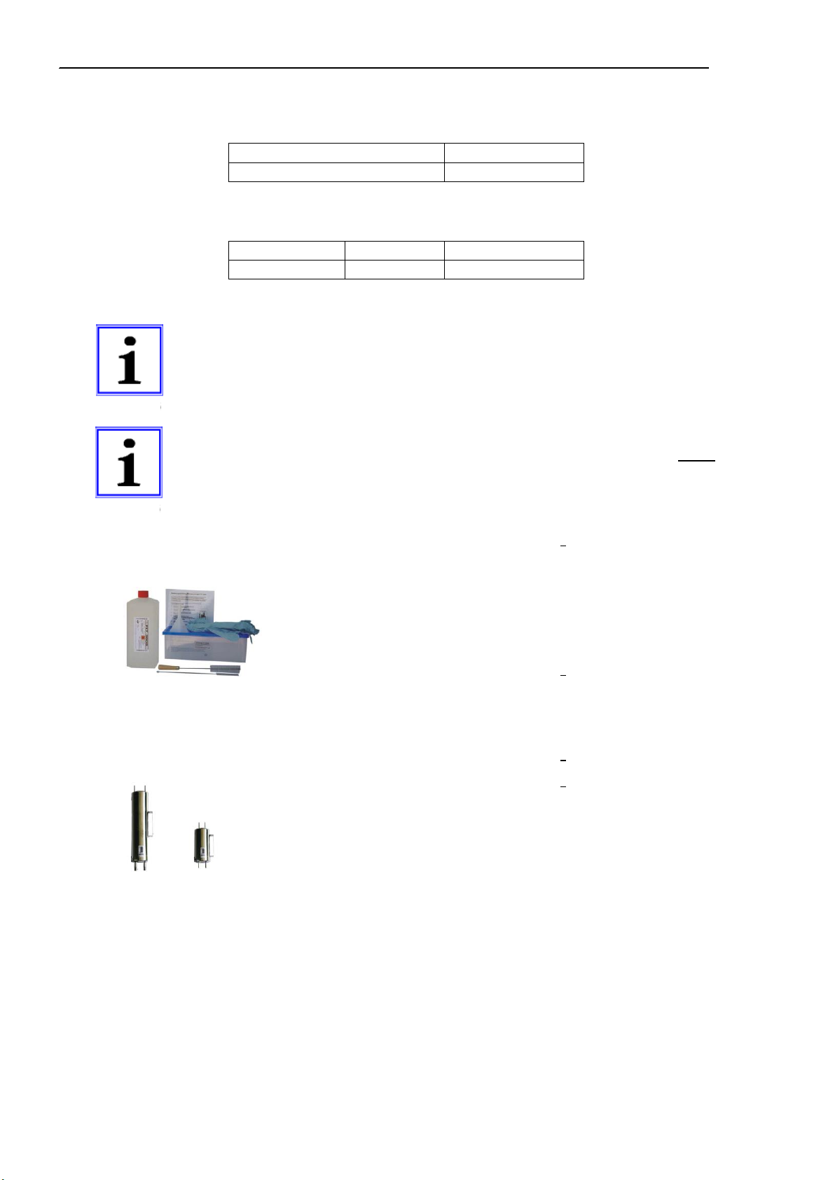
→Accessories SYCON CLEAN order no. 30-010 900
Cleaning set for acryl glass measuring-chambers
→1000 ml cleaning solution FIT 3000
→5 pairs of gloves
→2 brushes, funnel, container
→manual
FIT 3000 order no. 32-089 100
Cleaning solution for acryl glass measuring-chambers
→1000 ml cleaning solution FIT 3000
→Sample cooler PC 200 order no. 30-015 100
PC 400 order no. 32-015 200
For details please refer to our home page
www.rls-wacon.de
NOTE
NOTE

CHAPTER 2
SPECIFICATION AND OVERVIEW
PAGE 13
FIG.2.1 2.2 Overview –limit analyser –configuration
INLET PRESSURE OF
WATER SAMPLE
APPROX.0.5 -5.0 BAR
1-2BAR
RECOMMENDED
MAGNETIC STIRRER
WATER TREATMENT
PLANT
E.G.DEFERRIZATION
CONTROL-UNIT
REAGENT
BOTTLE 500 ML
DOSING-PUMP
DOSING-PLUG
WATER-OUTLET-PLUG
OPTICAL PATH WITH
LIGHT SOURCE AND
RECEIVER
WATER INLET-PLUG
SOLENOID VALVE
(BEHIND BOTTLE)
MEASURING-CHAMBER
WATER SAMPLE
DIRECTION OF FLOW
OPEN FUNNEL
(ATMOSPHERIC PRESSURE)
PAGE 14
SPECIFICATION AND OVERVIEW
CHAPTER 2
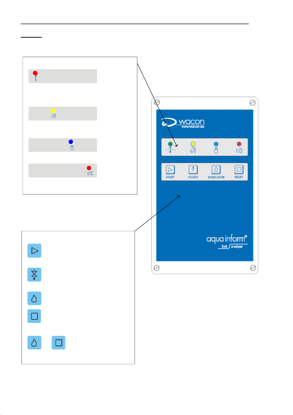
FIG.2.2 2.3 LIMIT ANALYSER –DISPLAY AND OPERATING PANEL
CONTROL BUTTONS
START START ANALYSIS
MANUALLY
FLUSH RINSE MEASURING-
CHAMBER MANUALLY
INDICATOR DOSE REAGENT MANUALLY
RESET QUIT ALARM
+NEW REAGENT BOTTLE
LED DISPLAY
TEST RESULT:
GREEN GOOD CONDITION /POWER ON
RED BAD CONDITION
YELLOW ANALYSIS ACTIVE
BLUE LACK OF REAGENT
RED ALARM /UNIT FAILURE

CHAPTER 2
SPECIFICATION AND OVERVIEW
PAGE 15
2.4 SPARE PARTS LIST FIG 2.3
Order No.
Description
33-090 002
Magnetic stirrer
33-090 008
Bottle Adapter
33-090 009
Bottle adapter
33-090 011
Suction lance
33-090 013
Inlet connection ¼"
33-090 014
Solenoid valve 24V complete
33-090 015
Outlet connection 6mm
33-090 016
Bulkhead fitting 6mm
33-090 038
Cartridge of peristaltic pump
33-090 044
Bulkhead fitting 6mm with threaded
connector
33-090 056
Activator for magnetic stirrer
33-090 210
O-Ring 9 x 1,5
33-090 217
O-Ring 17x2
33-090 218
O-Ring 3,2 x 2,5
33-090 700
Measuring-chamber complete
33-090002, 33-090701, 33-090711,
33-090712, 33-090713, 33-090716
33-090 701
Measuring-chamber
33-090 711
Inlet plug ¼"
33-090 712
Outlet plug ¼"
33-090 713
Actuator (LED)
33-090 716
Dosing plug
33-093 060
Bottle cap
33-090 023
Power supply circuit board 85-264 V
33-090 028
MAINTENANCE –KIT
33-090 024
Main board complete
1x 33-090 038
Cartridge of peristaltic pump
33-090 025
Control unit complete 85-264 Volt
1x 33-090 008
Bottle connector
33-090 026
Peristaltic pump complete
1x 33-090 011
Suction lance
33-099 007
Housing for control unit with lid
1x 33-090 217
O-ring 17 x 2
33-099 700
Operating manual German
3x 33-090 210
O-ring 9x1,5
33-099 701
Operating manual English
1x 33-090 218
Dosing-O-ring 3,2 x 2,5

PAGE 16
SPECIFICATION AND OVERVIEW
CHAPTER 2
2.5
Operation principle of Sycon 2501
An analysis cycle consists of 5 steps
[1]
Start delay:
The analysis start can be delayed by between
1 and 30 min (0 = no delay)
When monitoring hot water, it is necessary to cool the
water before it can be analysed. A cool water valve can
be opened via REL 3. The delay time should be set to
ensure that the water is cool enough before the inlet
valve is opened and the analysis begins.
↓
[2]
Washing and rinsing measuring-chamber with
sample water.
Programmable rinsing time: 5 sec-10 min
When the inlet valve is opened, the measuring-
chamber and pipes are rinsed until all traces of the
previous analysis are removed and the new water
sample is in the chamber.
↓
[3]
Filling measuring-chamber with sample water.
Monitoring of zero transmission without injection
of reagent
Before an analysis begins, an internal calibration takes
place based on a water sample without reagent
content. If the LED is defect a fault will be reported.
↓
[4]
Stirring water sample and injecting reagent.
Homogenisation and reaction phase while
stirring
The dosing pump injects a defined amount of indicator
into the water sample. The stirrer coil, activated at the
same time, mixes water and reagent. The reagent
causes colouration of the water sample in accordance
with the hardness components of the water. Reagents
are calibrated to change colour at certain limit values.
When unreasonable values are registered –e.g. no
reagent - a fault will be reported.
↓
[4.1]
Monitor light transmitted through the sample
water.
Evaluation of water hardness limit value alarm
Results are shown by the red/green LED. If the limit is
exceeded, an alarm will be set off. The result of the
analysis is evaluated on the following basis:
Below the limit = Good (green)
Over the limit = Bad (red)
NB. The result is inverted if switch S9 is set to ‘ON’.
↓
[5]
Flushing and rinsing measuring-chamber
NB: During Interval measuring-chamber is kept filled
with water.
Analysis start:
A automatically in 4 programmable
intervals: (0)15 / 30 / 60 / 120 minutes
B manually by pushing the Start-button
C via an external switch if the
programmable switch S10 is ‘ON’
Attention! If the interval (0)15 is
programmed, analysis runs can only be
triggered through an external switch
(interval 0 minutes).
By means of a flow monitor or a timer, the analyses
can be suppressed during periods when the water
conditioning system is switched off or in
regeneration, or no samples are being taken.
In this case the programmable switch S10 must be in
‘OFF’ position.

CHAPTER 2
SPECIFICATION AND OVERVIEW
PAGE 17
2.6 Functions
The SYCON 2501 Fe system has the following features:
[1] Automatic detection of iron leakage in accordance with limit value reagent used.
The monitoring process is fully automated, saving a significant amount of work by
eliminating the need for complicated manual procedures.
[2] Requires no periodic calibration.
[3] The interval between each analysis can be set to 15; 30; 60 or 120 minutes. The
start of analysis can be triggered by an external switch
[4] Reliable detection of iron leakages by means of limit value reagents.
[5] Monitoring of limit values with higher accuracy
When a BAD condition is detected, a reference analysis may be made after 4
minutes.
[6] LED status display is independent of language.
[7] Alarm functions:
When a hardness leakage is detected, an alarm is issued by switching the potential
free relay –REL 1. This alarm output may be used, for example, to send a signal to
a control panel, to sound a buzzer, to close a valve or to control a programme for the
regeneration of a water softening plant.
[8] Diagnostic programme:
If a fault occurs in the system an alarm is issued by switching the potential free relay
–REL 2. Technicians may run step by step through the diagnostic program to check
functions and find faulty parts in the device (→ page 48).
[9] Requires minimal maintenance:
Depending on measurement intervals and frequency of analyses respectively the
measuring-chamber has to be cleaned and reagent pipes and o-rings changed once
or twice a year (→ page 42).
[10] Minimal reagent consumption:
The reagent bottle is easily replaced. The 500 ml bottle does not need to be replaced
for approximately three or four months in typical applications.
(Note that more frequent replacement may be necessary, depending on the
application.)
[11] Compact in design, easy to install:
The main unit is installed easily on a wall.
Installation is a simple process (→ page 19).
[12] Digital input ‘IN’:

PAGE 18
SPECIFICATION AND OVERVIEW
CHAPTER 2
WARNING
NOTE
WARNING
The potential free switch of a flow monitor, a timer or any other condition
switch can be connected to this input. (→ page 26). When the contacts are
open, no analysis will be carried out during the programmed interval. As
an alternative, this input can be used as a start input.
Three potential free Relay Outputs - REL 1 / REL 2 / REL 3
The potential free relay outputs can be used to transmit a limit alarm (REL
1), a unit failure (REL 2) or an active analysis (REL 3) to a control panel
for example (→ page 25). Alternatively, signalling units or valves may be
activated.
[13] ’BOB’- operation
The abbreviation BOB comes from the German Betrieb ohne Beobachtung (operation
without permanent supervision) and follows a regulation of German TÜV (technical
inspection authority) especially for boiler houses, which requires reliability of
instruments for at least 72 hours.
The REL 2 output may be used to transmit a warning to a remote location
when the reagent needs to be replaced.
Analytical devices of type SYCON 2501 were specially designed for BOB-
operation (operation without permanent supervision). Boiler houses,
running in BOB-operation, require a qualitative monitoring of water
hardness in the boiler feed water according to the technical guideline TRD
604 (`Technische Regeln für Dampfkessel` published by German TÜV).
Analytical devices of type SYCON 2501 record the consumption of
reagent in order to ensure that in periods of operation without supervision,
a sufficient amount of reagent for reliable analysis is available in the bottle.
The sufficient amount of reagent should be calculated independently of
set analysis intervals for the next 72-hour operation.
If the very next 72-hour BOB-operation cannot be reliably guaranteed, an
alarm “lack of reagent” is issued via relay REL 2.
The reagent stocks can only be calculated correctly if the internal counter
is reset after installing a new 500 ml reagent bottle by pressing the RESET
key combination.
+ NEW REAGENT BOTTLE
•The device does not recognize the contents of the bottle, but resets
the counter of the metering pump, which then counts back starting
from 500 ml. You can reset the counter to zero only. If the keys are
pressed during an analysis without a new, full bottle of reagent being
installed, the reagent quantity will not be properly calculated, and the
alarm will not be issued on time or at the wrong time. This also applies
if the RESET action is forgotten.
Attention! If no iron is present in the water, no colour change will appear.
If no reagent is dosed, even for water with iron content no colour change
will appear and the reading will wrongly indicate no iron content.

CHAPTER 3
INSTALLATION AND COMMISSIONING
PAGE 19
CHAPTER 3 INSTALLATION AND COMMISSIONING
OF LIMIT ANALYSER
3.1 Installation Requirements
The analyser shall be used only to determine a parameter in the sample water.
Proper operation can only be guaranteed if reagents approved by the
manufacturer are used (→ page 12 or 27).
Changes to the electrical connections and the programming should only be
carried out by a qualified person.
The plant must meet the following conditions:
●The maximum allowable load capacity of the switching outputs and the overall
performance of the system must not be exceeded by the connected load (note
phase angle for inductive loads).
●All inductive loads (valves, motors, contactors, transformers) of the plant must
be equipped with suitable suppressors (e.g. RC element, varistor, diode, etc.)
●If the analyser could be influenced by external devices with high electro-
magnetic interference levels, these effects should be reduced by appropriate
measures. On the supply voltage input of the offending equipment appropriate
external interference suppression (line filter) should be fitted.
3.2 Instruction for Installation
When making connections to printed circuit boards, the following guidelines must
be followed:
●Do not apply excessive force to the terminals. Only apply the force necessary
to open the terminal (or to release the cable when disconnecting).
Push terminals are capable to receive single-strand conductors up to 1.5 mm².
However, multi-stranded conductors without cable shoes should not exceed
1.0 mm² and with cable shoes only 0.75 mm². According to the manufacturer,
use of cable shoes is not required.
To loosen a clamp, a small slot screwdriver, with a maximum blade width of
3mm is to be used.
●Observe all applicable electrical regulations.
●Work on electrical equipment of the plant / machinery must be performed by
a qualified electrician!
NOTE
WARNING
ELECTRICITY

PAGE 20
INSTALLATION AND COMMISSIONING
CHAPTER 3
3.3 Installation in 4 steps
The analyser can be mounted with or without protective enclosure. The
manufacturer offers a standard enclosure. The mounting and dimensions are
described in this guide:
Custom-built or tailor made enclosures for the devices of the series Limit
Analyser /SYCON 2501 / SYCON 2800 as well as devices with custom names
and labels that are technically based on these ranges are not described in detail
in this manual.
►step I a mounting without enclosure
Use 4 screws (max. 6 mm) to mount the unit on a wall or suitable support structure.
For spacing of holes see (Fig. 3.3→ page 24)
Or ►step I b mounting with enclosure
Use the 4 brackets included to mount the unit (Fig. 3.4→ page 24). The tabs can
be rotated by 45 degrees or 90 degrees outside. Alternatively, the unit can be
mounted without the brackets from the rear on a plate (M6). For spacing of holes
see page 24
In both variants, avoid direct sunlight and strong artificial light sources
→ disturbance of the optical path in the measuring chamber
→electromagnetic interferences by artificial light source
Do not install under dripping pipes.
►step II establish sample and drain pipe line
Use flexible pipe 6x4. Between water treatment plant and analyser a manual shut-
off valve and particle filter (if necessary) should be installed. Drainage should be
fed via short connection into an open funnel → run off to atmospheric pressure.
Make sure that you connect the inlet and outlet properly
→ (Figure 2.1 in page 13)
►step III electrical connections
Refer to information in figure 3.1 (terminal connection (→ page 21) and figure 3.2
(connection instructions (→ page 22).
Work on electrical equipment of the plant / machinery must be performed by a
qualified electrician! Observe all applicable electrical installation rules
→ applicable supply voltage 85 - 264 VAC, 47 - 63 Hz
NOTE
NOTE
WARNING
ELECTRICITY
This manual suits for next models
1
Table of contents
Other RLS Wacon Measuring Instrument manuals


Popular Measuring Instrument manuals by other brands


Securitytronix
Securitytronix ST-IP-TEST user manual

AutomationDirect
AutomationDirect ProSense DPM3-E Series user manual

Ntron
Ntron SenzTx Short form User Manual

Aqualytic
Aqualytic CHECKIT Comparator instruction manual

Air Weigh
Air Weigh LOADMAXX installation guide

Master cool
Master cool 52233 user manual


