RLS Wacon SYCON Silicate User manual

Operating manual
SYCON Silicate
Analyser for automated monitoring
Silicate concentration in process water

© RLS Wacon GmbH ∙ +49 (0)5121 28126 0 ∙ info@rls-wacon.de 2
General information ..............................................................................................................................................4
Safety instructions and symbols used ..........................................................................................................4
Transport............................................................................................................................................................5
Storage................................................................................................................................................................5
SYCON Silicate in detail .......................................................................................................................................6
Disposal note.....................................................................................................................................................6
Scope of delivery..............................................................................................................................................6
Device description............................................................................................................................................7
Functional principle..........................................................................................................................................9
General specification .......................................................................................................................................9
Technical data ...................................................................................................................................................9
Analytical properties......................................................................................................................................10
Inputs/Outputs ...............................................................................................................................................11
Maintenance intervals ...................................................................................................................................11
Indicators for monitoring the silicate concentration...............................................................................12
Installation.............................................................................................................................................................13
Wall mounting.................................................................................................................................................14
Water connection and drain.........................................................................................................................15
Work on pressurized water pipes ...............................................................................................................15
Operation with unpressurized sample water............................................................................................16
Electrical installation ...........................................................................................................................................17
Connection of the supply voltage...............................................................................................................18
Connection of the relay outputs .................................................................................................................19
Power interface, RS-485 and input contacts............................................................................................23
Connection of external components ...............................................................................................................25
Switch for external analysis start ................................................................................................................27
Connection of a water meter for analyses in the quantity interval......................................................28
Flow switch......................................................................................................................................................29
Switchable interval reset on (INPUT 1) with PLC control......................................................................30
Connection of a switch Error RESET to (INPUT 2)..................................................................................31
Signal lamp/horn.............................................................................................................................................32
Relay function analysis active (analysis delay)..........................................................................................34
Analog current interface ...............................................................................................................................35
Operating status via analog current interface ..........................................................................................36
Operation ..............................................................................................................................................................37
Display and keypad ........................................................................................................................................39
Display Menu ..................................................................................................................................................40
Display indication during a measurement .................................................................................................41
Display of measured value history..............................................................................................................42
Display Selection menu.................................................................................................................................42
Display Selection list......................................................................................................................................42
Display with value input................................................................................................................................43
Configuration........................................................................................................................................................44
Factory settings ..............................................................................................................................................44
Configuration Wizard ....................................................................................................................................45
Content

© RLS Wacon GmbH ∙ +49 (0)5121 28126 0 ∙ info@rls-wacon.de 3
Menu structure ...............................................................................................................................................63
Operation ..............................................................................................................................................................64
Manual and automatic operation ................................................................................................................64
Main menu.......................................................................................................................................................64
Info display.......................................................................................................................................................65
Behaviour in the event of a power failure.................................................................................................65
SD card .............................................................................................................................................................66
Maintenance and service ...................................................................................................................................68
Cleaning the measuring chamber................................................................................................................69
Change of peristaltic pump cassettes, hoses and seals ..........................................................................71
Changing the indicator bottle ......................................................................................................................74
Calibrating the device....................................................................................................................................75
Change battery................................................................................................................................................75
Software update .............................................................................................................................................76
Good and bad counter...................................................................................................................................76
Diagnostic functions............................................................................................................................................77
Display ..............................................................................................................................................................77
Sensor ...............................................................................................................................................................77
Solenoid valve .................................................................................................................................................77
Indicator A........................................................................................................................................................77
Indicator B........................................................................................................................................................78
Indicator C........................................................................................................................................................78
stirring wings ...................................................................................................................................................78
Relay 1 to 4......................................................................................................................................................78
Current interface ............................................................................................................................................78
Input 1 and 2 ...................................................................................................................................................79
Error analysis ........................................................................................................................................................80
Analysis does not start ..................................................................................................................................80
Error message E11 Indicator........................................................................................................................80
Error message E12 Water flow....................................................................................................................80
Error message E13 Optics ............................................................................................................................80
Notes......................................................................................................................................................................81
Appendix................................................................................................................................................................82
Spare parts.......................................................................................................................................................82
Maintenance sets ...........................................................................................................................................84
Accessories ......................................................................................................................................................85
Declaration of Conformity............................................................................................................................86

© RLS Wacon GmbH ∙ +49 (0)5121 28126 0 ∙ info@rls-wacon.de 4
General information
These operating instructions describe the installation and operation of the SYCON Silicate analyzer.
Installation and commissioning may only be carried out by an authorized specialist.
The device may only be operated under the conditions described in these operating instructions.
The device may only be used for the specified purpose. When installing and operating the analyzer,
all locally applicable regulations (such as EN, DIN, VDE, UVV) must be observed.
The analyzer is used for the automatic determination of the SILICAT concentration in the process
water. Proper operation can only be guaranteed if the indicators and spare parts recommended by
us are used.
Changes to the electrical wiring and programming may only be carried out by a qualified specialist.
The water connection lines to the device should be kept as short as possible and should not be laid
together with mains lines or in their immediate vicinity. In the vicinity of strong electromagnetic
radiators, interference with the analysis may occur. In this case, special interference suppression
measures must be taken, in particular the EMC guidelines must be observed.
It is recommended that you always have access to the analyzer during familiarization with the aid of
this operating manual in order to be able to understand the explained relationships and functions
immediately. Since certain areas build on each other, it is advisable to work through the chapters in
the specified order.
If you have any questions regarding the use of the analyzer, you will receive support from our
partners or from us. You can reach us by telephone during normal business hours or by email. The
contact details of our technicians and partners can be found on our website.
Safety instructions and symbols used
In this operating manual, you will find various safety instructions that point out possible risks when
handling the analyzer. This concerns in detail dangers for
•People,
•this product or related equipment and devices,
•the working environment.

© RLS Wacon GmbH ∙ +49 (0)5121 28126 0 ∙ info@rls-wacon.de 5
Various symbols in these operating instructions indicate special dangers in order to prevent
personal injury and damage to equipment. Please read the entire text completely before starting
work.
This symbol draws your attention to useful tips that will help you to better
understand the device.
This symbol is a general warning that indicates circumstances that must be
observed.
Pressure
This symbol warns that you should expect to encounter lines under pressure.
Voltage
This symbol indicates the danger of electric current and the danger to
persons and electronic components and assemblies.
Wear safety goggles
Wear protective gloves
Transport
Immediately upon receipt, check that the device is complete and that it has
not been damaged in transit. The analyzer is shipped in a transport-safe
condition. Nevertheless, damage may occur during transport. Immediately
notify the delivery person of any transport damage.
Protect the analyzer from possible damage during transport. Remove any
liquids that may still be in it beforehand. Remove the indicator bottle and
close it to prevent the indicator from leaking.
Storage
Store the analyzer in a dry place at temperatures between 0 - 45 °C and out
of direct sunlight.
General information

SYCON Silicate in detail
Disposal note
The device must not be disposed of in the residual waste. Take the device to a collection point. The
battery must be disposed of separately.
Alternatively, you can return the analyzer to your dealer or to us for disposal.
Scope of delivery
The SYCON Silicate analyzer is characterized by the following features:
•reliable, accurate and fully automatic analyser with suitable indicators for measuring the
silicate concentration in the measuring range from 0.3 to 10 mg/l.
•Monitoring of 2 programmable limit values
•Simple commissioning through configuration wizard
•self-calibrating and self-monitoring
•easy maintenance and cleaning
•non-corrosive plastic housing
•compact design
•multicolour, multilingual graphic display
•Relay output for limit value
•Relay output for fault indication
•Relay output for feed pump, indicator alarm or cooling water valve
•analog output 0/4 - 20 mA for measured value or status message
•2 programmable digital inputs
•Measurement data memory and measurement data log on SD card
•no condensation in the optics
•Software updates via SD card
The SYCON Silicate can be used for automatic monitoring of mixed bed
filters. Regular maintenance of the device is necessary for trouble-free
operation.
Article description
Part number
SYCON Silicate
30-100178

© RLS Wacon GmbH ∙ +49 (0)5121 28126 0 ∙ info@rls-wacon.de 7
Device description
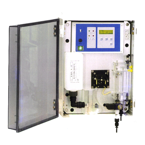
The analyzer consists of the following components: The control unit with graphic display and
control panel is located on the left side of the device. On the lower control housing there are 5
cable feed-throughs. The dosing pumps for indicator A, B and C are located in a separate housing at
the top right of the control unit.
The dosing pumps are plugged onto the motor shafts of the motors and snap into the receptacles.
They can be removed without tools. The measuring chamber is attached to 2 guide pins on the
control housing. It can also be removed without tools and is released with 2 captive locking pins.
The metering plugs, actuator plugs, inlet and outlet plugs are attached to the measuring chamber in
the same way and can be released quickly; only the screwable metering plugs require an open-end
wrench.
To the right of the control is the measuring chamber, which is basically pressureless and always
filled to avoid contamination. In the middle of the measuring chamber is the actuator plug with a
white high-power LED. The sensor system is located in the housing. Below the measuring chamber
is an agitator (magnetic stirrer), which is firmly connected to the housing.
On the outside of the housing are the water connections for hoses with an outer diameter of 6 mm
for feeding the sample water.
The drain has an outer diameter of 1/4 inch and should be kept as short as possible. All connections
are firmly screwed to the housing.
To the left of the indicator bottles is the solenoid valve on the supply line.
Illustration: Front view with door open
SYCON Silicate in detail

© RLS Wacon GmbH ∙ +49 (0)5121 28126 0 ∙ info@rls-wacon.de 9
Functional principle
The SYCON Silicate is an analyzer for automated monitoring of the silicate concentration in the
process water according to the colorimetric method. By adding an indicator to the water sample, a
color reaction is generated. The SYCON calculates the silicate concentration in the process water
by the colour change of the indicator sample. The device can only determine one parameter at a
time. Parameter and measuring range are determined by the indicator used.
General specification
Parameter
Value / Range
Power supply
(230 V version)
85 - 264 VAC (47...440 Hz)
Power consumption
30 VA (in operation)
3.5 VA (standby)
Resilience
Load capacity of the relays with internal power supply 1 A from
terminals 1 to 4
Load capacity of the relays with external power supply 2.5 A
Protection class
IP54
Storage temperature
0 °C - 45 °C
Ambient temperature
10 °C - 45 °C
Measured water temperature
5 °C - 40 °C
Humidity
20 - 90 % RF
(without ice or condensation)
Inlet water pressure
min: 0.5 bar - max: 5 bar / recommendation 1 - 2 bar
Inlet water in general
clear, free of solids, without gas bubbles,
Water quality requirements
for silicate concentration
measurement
pH:
9 - 10
Iron:
< 3 ppm
Copper:
< 0.2 ppm
Aluminum:
< 0.1 ppm
Manganese:
< 0.2 ppm
free from grease, oil and turbid matter
Technical data
Parameter
Value / Range
Installation
Wall mounting in closed rooms
Dimensions
600 x 488 x 255 mm (W x H x D)
Weight
approx. 8,7 kg
SYCON Silicate in detail

Parameter
Value / Range
Measuring method
Colorimetric
Measuring range
The measuring range with the reagents Silicate-A, Silicate-B and Silicate-C is
0.3 to 10 mg/l Silicate.
Accuracy
Measurement accuracy:
± 5 % of the maximum measured value of the respective indicator used
Repeatability:
± 2.5 % of the maximum measured value of the respective indicator used
Please note:
Disturbances such as air bubbles or turbidity in the water sample can lead to
fluctuating measured values.
Current interface
± 0.3 mA
Indicator
consumption
Reagent A: approx. 1ml/analysis, Reagent B,C: approx. 0.5 ml/analysis,
Measuring time
approx. 15 min, depending on the set flushing time
Number of
analyses
Reagent A: approx. 500 analyses / 500 ml indicatorReagent
B,C: each approx. 1000 analyses / 500 ml indicator
Durability of the
indicators
2 years if stored properly (< 25 °C, dark)
Water
consumption
approx. 2 l sample water per analysis at 2 bar
The water consumption varies depending on the inlet pressure and the set
flushing time.
SYCON Silicate in detail

© RLS Wacon GmbH ∙ +49 (0)5121 28126 0 ∙ info@rls-wacon.de 11
Inputs/Outputs
Parameter
Value / Range
4 relay outputs
max. 250 VAC / VDC 1 A
as potential-free outputs NC/NO
the relays provide the following functions:
•Limit value alarm 1
•Limit value alarm 2
•Device error
•Analysis active with switchable delay time
•Indicator message
2 signal inputs
galvanically isolated contact input
•Start analysis
•Water meter
•Flow switsch
•Interval reset
•Analysis abort / fault reset
Analog output
0 - 20 mA / 4 - 20 mA
Resolution: < 100 μA
max. load: 750 Ω
Maintenance intervals
Interval
Maintenance
Four weekly
Cleaning the measuring chamber
In case of high ambient and water temperatures or water with a high
organic load, the cleaning intervals may have to be shortened.
every 15,000 analyses or
after 12 months of
operation
Cleaning the measuring chamber (as above),
Installation Maintenance kit: Change the peristaltic pump cassettes,
hoses and seals. Reset of the maintenance counter.
SYCON Silicate in detail

SYCON Silicate in detail
Indicators for monitoring the silicate concentration
NameIndicator
Measuring range
Art. No.
500 ml bottle
Silicate A
0.3..10 mg/l Silicate
32-010 101
Silicate-B
32-010 102
Silicate-C
32-010 103
A set of reagents Silicate-A, Silicate-B and Silicate-C is required for the
measurement.
The indicators are also available in a value pack. This contains:
Quantity 500 ml
NameIndicator
Measuring range
Art. No.
Container
Bottles
2
Silicate A
0.3..10 mg/l Silicate
32-010 100
1
Silicate-B
1
Silicate-C
The content of the indicator container is sufficient for approx. 1000 analyses.

© RLS Wacon GmbH ∙ +49 (0)5121 28126 0 ∙ info@rls-wacon.de 13
Installation
The installation should be done in the following steps to avoid errors:
•Install the analyzer in a dry, easily accessible location with good visibility.
•Fix the housing stably with screws according to the instructions.
•Connect the device electrically and make sure that the input voltage is correct. Check the
rating plate to make sure.
•Connect inlet and outlet according to the installation instructions. Ensure that the inlet
pressure is correct and that the outlet is kept free and short.
•Insert the indicators and connect them to the dosing pumps. Make sure that the connecting
hoses are not twisted.
•Do not switch on the unit until all preliminary work has been completed and the control
housing is closed.
•Now make the device settings on the device.
The sample water must be clear and free of solids. Otherwise, a filter must be
provided upstream of the analyzer. Solids in the water can damage the
solenoid valve or prevent it from closing. If the solenoid valve is blocked or
fails to open or close, the flow through the measuring chamber will not be
correct. This leads to incorrect measurements.
The temperature of the sample water must be between 5 and 40 °C.

Installation
Wall mounting
The analyzer is supplied with a suitable housing. As an accessory pack, you will receive 4 mounting
brackets that are attached to the back of the housing.
To open the unit, the available free space should be at least 650 x 500 mm (W x H).
Figure: Drilling plan for mounting the analyzer on the wall

© RLS Wacon GmbH ∙ +49 (0)5121 28126 0 ∙ info@rls-wacon.de 15
Installation
Water connection and drain
Position
Description
D
Cable glands for electrical connection
W
Water inlet sample - Connection for hose with 6 mm outer diameter
V
Water drain - Connection for hose with 1/4 inch outer diameter
Work on pressurized water pipes
Pressure
Maintenance and repair work may only be carried out by qualified personnel.
•Before starting work, make sure that all lines are depressurized.
•Hoses, connections and seals must be checked regularly and, if necessary, replaced as a
preventive measure, even if they show no visible damage. Maintenance intervals must be
observed.
•Before recommissioning after maintenance, make sure that all connections, glands and seals
are properly installed. Check that all housing parts are closed and filters or other parts
connected to the unit are correctly installed.
•Remove all tools, spare parts or other material required for maintenance before
commissioning.
•Clean the unit, absorb any spills, and leave the unit in a clean condition.
•Check that all safety devices are in place and operational.

The analyzer has two connections with bulkhead fittings for plastic tubing:
one with an outside diameter of 6 mm for the water inlet (W) and one with an
outside diameter of 1/4 inch for the water outlet (V). These are simply
plugged into the fittings.
Pressure
The inlet pressure of the water sample must be between 0.5 and 5.0 bar.
The recommended inlet pressure of the water sample should be between 1
and 2 bar.
The hose length of the water drain must not be longer than 2 m and must
lead away vertically downwards. The system must be able to relax freely
against the atmospheric pressure. There must be no back pressure greater
than the inlet pressure. The water drain is pressureless into an open funnel or
drain.
Operation with unpressurized sample water
If the sample water is unpressurized, a pressure-controlled diaphragm or submersible pump is
required to convey the sample water into the measuring chamber of the analyzer.
Installation

© RLS Wacon GmbH ∙ +49 (0)5121 28126 0 ∙ info@rls-wacon.de 17
Electrical installation
Voltage
Work on electrical connections may only be carried out by authorised
specialist personnel in compliance with the current regulations. All lines must
be de-energized.
The permissible supply voltage is 85 - 264 VAC (47...440 Hz).
Open the cover of the control unit by loosening the four screws in the corners of the cover.
Figure: Back of the cover (left side), circuit board (right side)
Position
Description
A
Battery holder
B
Pump housing / solenoid valve connection
C, M
Display connection
D
Actuator plug LED connection
E
Fuse (5 x 20 mm) 1 A carrier
F
Main switch connection
G
4 x relay
H
Agitator connection
K
RGB sensor
L
SD card socket
N
Audio signal generator

Connection of the supply voltage
Figure: Terminals for connecting the supply voltage (blue border)
Connection of the supply voltage
Terminal designation
Description
16 PE
Grounding
17 PE
Grounding
18 L (power in)
Supply voltage between L and N 85 - 264 VAC (47...440 Hz)
19 N (power in)
Output terminals switched via the device switch
Terminal designation
Description
1 L power out
Switched supply voltagebetween L and N 85 - 264 VAC (47...440
Hz)
2 L power out
3 N power out
4 N power out
Voltage
The maximum connected load of all consumers must not exceed
250 VA / 1 A.
Electrical installation

© RLS Wacon GmbH ∙ +49 (0)5121 28126 0 ∙ info@rls-wacon.de 19
Connection of the relay outputs
Figure: Terminals for connecting the relay outputs (blue border)
The relays are designed as changeover contacts, with a common connection and the switching
outputs NC and NO.
RELAY 1 (relay 1): Limit value exceeded (limit value alarm 1)
Terminal designation
Description
Connection
5 COM
Relay 1 COM common connection
see page 9
Load capacity
6 NC
Relay 1 NC normally closed
7 NO
Relay 1 NO normally open
RELAY 1 / Relay 1 function (limit value alarm 1):
If the measured value of the sample is within the nominal range set in the instrument, relay 1 drops
out and establishes a connection from COM to NC. In addition, the R1 symbol is not highlighted in
the display.
If the measured value of the sample exceeds the limit value 1 set in the device, relay 1 is energized
and establishes a connection from COM to NO. In addition, the R1 symbol is highlighted in black in
the display.
Electrical installation

Electrical installation
Figure: Terminals for connecting the relay outputs (blue border)
RELAY 2 (relay 2): Limit value 2 - measured value below detection threshold
Terminal designation
Description
Connection
20 COM
Relay 2 COM common connection
see page 9
Load capacity
21 NC
Relay 2 NC normally closed
22 NO
Relay 2 NO normally open
Relay 2 Function limit value alarm 2:
The limit value 2 alarm indicates that the value has fallen below the start of the measuring range. In
this case, there is no silicate in the water or there is no indicator in the sample due to a dosing fault.
The relay can also be linked to relay 4 in the low indicator mode.
If the measured value of the sample is within the nominal range set in the device, relay 2 drops out
and establishes a connection from COM to NC. In addition, the R2 symbol is not highlighted in the
display.
If the measured value of the sample exceeds the limit value 2 set in the device, relay 2 is energized
and establishes a connection from COM to NO. In addition, the symbol R2 is highlighted in black in
the display.
This manual suits for next models
1
Table of contents
Other RLS Wacon Measuring Instrument manuals
Popular Measuring Instrument manuals by other brands

Leuze electronic
Leuze electronic MSI-SR-LC21M Series Original operating instructions
Grunbeck
Grunbeck GENO-Multi Niveau Operation manual
SMS
SMS ISKRA ME371 Technical description
LaserLiner
LaserLiner LaserRange-Master Gi5 manual
Thermo Scientific
Thermo Scientific 42i instruction manual
HP
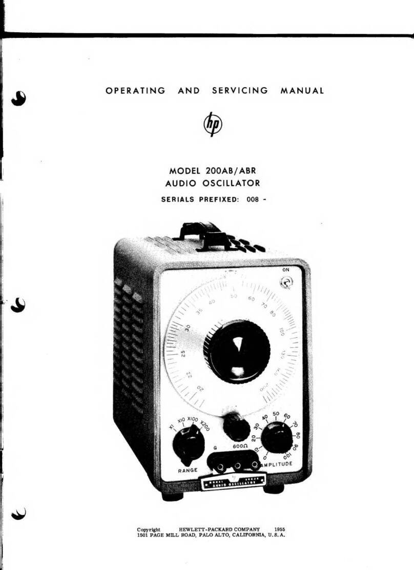
HP 200AB Operating and servicing manual

