RLS Wacon SYCON 3000 C User manual

OPERATING MANUAL
SYCON 3000 C
Analytical Instrument to Measure the
Carbonate Hardness of Water

Table of Contents
Functional description..........................................................................................................................1
Operating displays ................................................................................................................................2
LED control lamps................................................................................................................................ 2
LCD display.......................................................................................................................................... 3
INFO displays....................................................................................................................................... 4
Indicator type and hardness unit ...................................................................................................... 4
Service telephone number ............................................................................................................... 4
Input states ....................................................................................................................................... 4
Output states .................................................................................................................................... 4
Analysis result counter ..................................................................................................................... 4
Software status................................................................................................................................. 4
Internal measurement and blank value ............................................................................................4
Manual control.......................................................................................................................................5
Analysis start........................................................................................................................................ 5
Start extra flush .................................................................................................................................... 5
Start servicing ...................................................................................................................................... 5
Test output relays................................................................................................................................. 5
Acknowledge horn................................................................................................................................ 5
End....................................................................................................................................................... 5
Acknowledge relays ............................................................................................................................. 5
Messages................................................................................................................................................6
Refill indicator....................................................................................................................................... 6
Indicator lack analysis stop .................................................................................................................. 6
Error blank value.................................................................................................................................. 6
Internal measurement too high ............................................................................................................ 6
Internal measurement too low.............................................................................................................. 6
Water hardness over/underrun ............................................................................................................ 6
Permanent signal 1 .............................................................................................................................. 6
Permanent signal 2 .............................................................................................................................. 6
Input functions.......................................................................................................................................7
Start analysis........................................................................................................................................ 7
Stop analysis........................................................................................................................................ 7
Reset relay ........................................................................................................................................... 7
Water meter ......................................................................................................................................... 7
Output functions....................................................................................................................................8
Pulse signal.......................................................................................................................................... 8
Permanent signal 1 .............................................................................................................................. 8
Permanent signal 2 .............................................................................................................................. 8
Analysis active ..................................................................................................................................... 8
Signal relay .......................................................................................................................................... 8
Recorder outputs...................................................................................................................................9
Recorder output RC 1 .......................................................................................................................... 9
Recorder output RC 2 .......................................................................................................................... 9
Changing and calling up the programme data.................................................................................10
1. Reagents and limit value................................................................................................................ 11
Indicator type .................................................................................................................................. 11
Physical unit of water hardness...................................................................................................... 11
Correction factor ............................................................................................................................. 11
Limit value of the water hardness................................................................................................... 11
Limit value monitoring .................................................................................................................... 11
2. Analysis sequence ......................................................................................................................... 12
Flush time ....................................................................................................................................... 12
Analysis interval 1........................................................................................................................... 12
Analysis interval 2........................................................................................................................... 12
3. Selection of the programmable input functions.............................................................................. 13
Input: IN 1 ....................................................................................................................................... 13
Input: IN 2 ....................................................................................................................................... 13
Activation of the input functions...................................................................................................... 13

4. Parameters of the input functions.................................................................................................. 14
Input function "START" .................................................................................................................. 14
Delay time Analysis start ............................................................................................................ 14
Input function "STOP" .................................................................................................................... 14
Delay time Analysis stop ............................................................................................................ 14
Input function "Reset relay"............................................................................................................ 14
Delay time Delete relay .............................................................................................................. 14
Input function "Water meter" .......................................................................................................... 14
Water volume 1 between the analyses ...................................................................................... 14
Water volume 2 between the analyses ...................................................................................... 14
Pulse interval of the water meter................................................................................................ 14
5. Selection of the programmable output functions ........................................................................... 15
Output: OUT 1................................................................................................................................ 15
Output: OUT 2................................................................................................................................ 15
Output: OUT 3................................................................................................................................ 15
Activation of the output function..................................................................................................... 15
6. Parameters of the output functions................................................................................................ 16
Output function: Pulse signal ......................................................................................................... 16
Pulse length................................................................................................................................ 16
Number of bad messages .......................................................................................................... 16
Output function: Permanent signal 1 ................................................................................................. 16
Automatic delete function 1 ........................................................................................................ 16
Number of the bad messages .................................................................................................... 16
Output functions: Permanent signal 2........................................................................................... 17
Automatic delete function 2 ........................................................................................................ 17
Number of the bad messages .................................................................................................... 17
Activation through a fault............................................................................................................ 17
Output function: Analysis is running............................................................................................... 17
Analysis delay............................................................................................................................. 17
Output function: Signal relay.......................................................................................................... 18
Fault messages .......................................................................................................................... 18
7. Activation of the buzzer ................................................................................................................. 18
8. Recorder ........................................................................................................................................ 19
Recorder output RC1 = operational sequence........................................................................... 19
Recorder output RC2 = water hardness..................................................................................... 19
9. Entering a code number ................................................................................................................ 20
Service setting 1 and 2 ....................................................................................................................... 21
1. Switching the metering pump on and off.................................................................................... 21
2. Initiating a flush procedure and adjusting the electronics .......................................................... 21
Test of the output relays..................................................................................................................... 22
Activating and deactivating relays.................................................................................................. 22
Installation of the instrument............................................................................................................. 23
Commissioning the instrument ......................................................................................................... 23
Dimensions and drilling plan for the assembly ............................................................................... 24
Measurement diagramme................................................................................................................... 24
Terminal plan....................................................................................................................................... 25
Internal connections ........................................................................................................................... 25
Notes on connections......................................................................................................................... 26
Mains input......................................................................................................................................... 26
Mains output ...................................................................................................................................... 26
Inputs ................................................................................................................................................. 26
Relay outputs..................................................................................................................................... 27
Recorder interface ............................................................................................................................. 28
Connection and programming examples ......................................................................................... 28
Replacing components....................................................................................................................... 31
Instrument maintenance..................................................................................................................... 31
Spare parts list..................................................................................................................................... 32
Technical data...................................................................................................................................... 33

Functional description
1
SYCON
3000 C
Functional description
The analytical instrument of the type SYCON
3000 C is used for the fully automatic measure-
ment of the carbonate hardness of water.
Instrument models are also available to measure
the total hardness Typ SYCON 3000 H and the
Minus m-value Typ SYCON 3000 M.
Measurements can be initiated as follows:
1. Press the "START" button on the instrument
control panel.
2. Activate an external remote switch.
3. Automatic - in programmable time intervals.
4. Automatic – after a programmable flow rate
(volume).
After the value of a predetermined limit is ex-
ceeded (overrun) or fallen below (underrun), a
shorter time interval or a lesser flow rate can be
programmed for the following automatic meas-
urement.
One-component reagents are used for different
measurement ranges. This enables high meas-
urement accuracy with minimum use of reagents,
tailored to the specific case of application. These
reagents can be kept for at least 2 years if stored
appropriately.
Water samples with a temperature over 45 °C
must be cooled prior to analysis. In order to cool
down the test water over a cooler only when the
sample is taken, it is possible to trigger a cooling-
water valve before the input valve is opened.
Each measurement begins with an adjustable
flushing phase. This ensures that the water from
the treatment plant is measured and not the water
that has remained in the supply line since the last
measurement.
Subsequently, the measuring chamber is filled
with a new sample, and the optical value is ascer-
tained without the addition of the reagent (blank
value).
During the measurement of the water hardness,
the reagent is continually added – regulated by a
stepping motor – until a colour transition is regis-
tered. The quantity of reagent used is a measure
of the water hardness.
Signal devices and valves can be switched if a
programmable limit is exceeded or fallen below
and a programme mechanism can be addressed
for the regeneration of a treatment plant.
An analogue output 0(4)-20mA signals the differ-
ent states of the instrument. A further analogue
output delivers a signal in proportion to the
measured water hardness.
In order to suppress undesired bad-water mes-
sages, the first bad messages can be ignored.
Following the measurement, the measuring
chamber is flushed immediately. This prevents a
premature contamination of the measuring
equipment through the colourants of the reagent.
The built-in feed valve is closed during the ana-
lytical pauses to prevent unnecessary water con-
sumption.
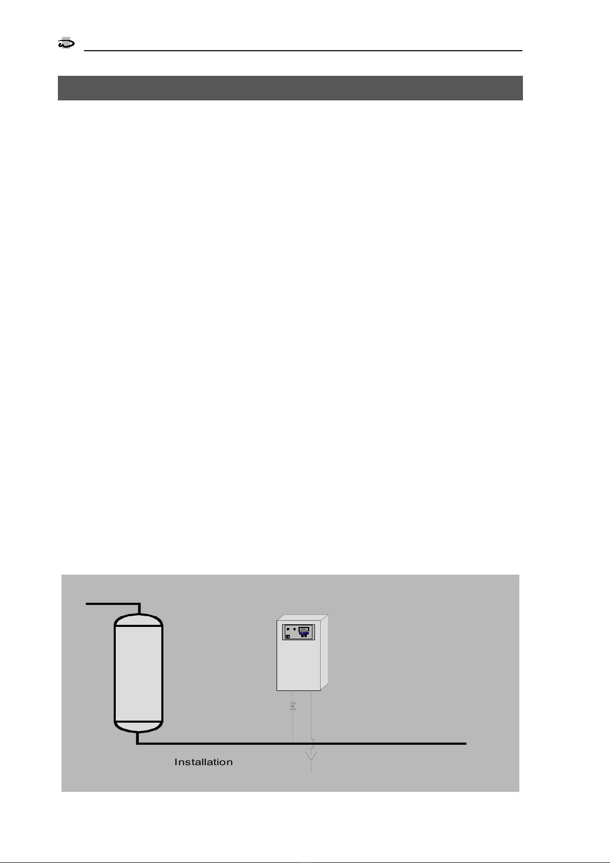
Water softening plant SYCON 3000 C
Analytic al Instrument to Measure the Carbonate Hardness of Water
Installation example
Operating displays
LED control lamps
2
SYCON
3000 C
Operating displays
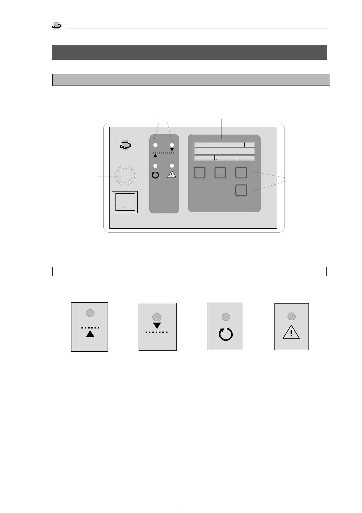
LED control lamps
Coloured control lamps indicate the most important operating states:
The control lamps "Soft water" and "Hard water" display the result of the last analysis.
During a new analysis, the control lamps "Analysis“ and the lamp displaying the last result (i.e. "Soft water" or
"Hard water") blink.
If both the control lamps "Soft water" and "Hard water" are blinking, no analysis result is available, e.g. after
the instrument has been switched on.
In the event of a malfunction or disorder, the control lamp "Fault" blinks.
Additional information can be found on the LCD display.
MT 4A
ON
F1
START FLUSH
10 m 2 *
F2 F3
0.90°m g/l
Limit
> 0.5
KEY
Fuse
Power switch
LED - control lamps LCD - display
Keys
Soft water (green)
Hard water (red)
Fault (red)
Analysis (yellow)

Operating displays
LCD display
3
SYCON
3000 C
LCD display
Displays between the analyses
9m
| 5 , 3 1 c b m
| 2 *
L i m i t
1 7 m g / l
> = 9 . 0
S T A R T F L U S H
In the upper line of the LCD display, the time re-
maining until the next analysis is shown on the left
(e.g. 9 minutes). If the instrument has been pro-
grammed accordingly, the flow-rate volume until
the next analysis is also displayed alongside the
time (e.g. 5.31 cbm).
If the display "Stop" is shown instaed of the mini-
ute value, an imminent analysis is delayed by the
activated input "STOP".
An analysis can be started manually at any time.
If, for example, the display 1* appears on the
right in this line, this indicates that, when the limit
value is next exceeded or fallen short of, the pro-
grammed output function e.g.
"Impulse signal" will be activated.
If, for example, the display 2* appears, the func-
tion will only be activated after 2 successive
over/underruns of the limit.
In the middle of the display, the last measured
water hardness is displayed (e.g. 17 mg/l. Values
outside the measuring range are designated by
the symbols < and > and by a specification of
the measurement range limit
(e.g. <8 mg/l).
Next to this, the programmed limit value appears
with the symbols "<=" for an underrun of this
limit and, with the corresponding programming,
">=" for an overrun of the limit value
(e.g. >=160 mg/l).
After the instrument has been switched on, the
value "----" is displayed until the first measure-
ment.
The lower line gives information on the possible
functions of the buttons arranged beneath it (e.g.
"START" and "FLUSH").
Displays during the analyses
B l a n c v a l u e 2 s 1 *
L i m i t
1 7 m g / l
> = 9 . 0
E N D
During an analysis, the phases Flush, Blanc value,
Titration and Wash with the remaining times are
displayed in the upper line (e.g. Blanc value 2
seconds).
T i t
L i m i t
1 7 m g / l
> = 9 . 0
E N D
During titration, however, the display "Tit" is
shown with two bars alongside it. The lower bar
designates the limit value of the optical measure-
ment dependent on the titration progress. The
upper bar designates the current measured value.
As soon as the upper bar attains the length of the
lower bar, the measured value is saved and, after
a short delay, the newly measured water hardness
is then displayed.
Additional displays
I n d i c a t o r
refill
P o s s i b l e a n a l y s e s 2 4
H O R N
Different messages or fault indications alternate
with the displays between and during the analyses
(see the section "Messages" on page 6).
Note
With the help of the "KEY" button on the right, fur-
ther functions for the "F3" button can be called
up.

Operating displays
INFO display
4
SYCON
3000 C
INFO displays
With the help of the INFO key, different information or values can be requested. Modifications will be de-
scribed – as far as possible – in the programme section "Changing and reading out the programme data".
Only the Service telephone munber can be altered during the display.
Press the KEY key repeatedly until the key function INFO is displayed for the right-hand key F3.
Press the INFO key. The first information is displayed.
Other information can be obtained by further pressing the INFO key.
9 m 5 , 3 1 c b m 2 *
L i m i t
1 7 m g / l
> = 8 0
S T A R T I N F O
Indicator type and hardness
unit
I n d i c a t o r C A 9
R a n g e : 8 - 1 6 0
H a r d n e s s u n i t : m g / l
E N D I N F O
The programmed indicator type, the associated
hardness range and the unit of hardness are dis-
played.
Service telephone number
S e r v i c e t e l e p h o n n o .
0 5 1 2 1 1 2 3 4 5 6 7 8
▲
►# I N F O
The Service telephone number is displayed.
Altering the telephone number:
SELECTING DIGITS:
Press the key with the "
!
" symbol.
CHANGING DIGITS:
Press the key with the "
#
" symbol.
Input states
I n p u t s t a t e s
S T A R T = - S T O P = -
E N D I N F O
The functions of the inputs IN1 and IN2 with their
current switching states are displayed.
A horizontal line "-" alongside the designation
means: Input not active.
A vertical line "|" alongside the designation
means: Input active.
Output states
O u t p u t s t a t e s
P u l s e =
- P e r m a n . 1 = -
M e s s a g e = -
E N D I N F O
Programmed functions of the outputs OUT1,
OUT2 and OUT3 with their current switching
states are displayed.
A horizontal line "-" alongside the designation
means: Output not active.
A vertical line "|" alongside the designation
means: Output active.
Analysis result counter
A n a l y s e s c o u n t e r
S O F T : 1 4 3 6
H A R D : 4 5
E N D I N F O
In the first line the number of all analyses con-
ducted with the result Water SOFT and in the
second line the number with the result Water
HARD is displayed.
The max. number totals 9'999'999. Thereafter,
the counters are reset to zero.
Software status
S o f t w a r e v e r s i o n
S Y C O N 3 0 0 0 C 0 1 0 1 . 2 5
E N D I N F O
The software is continuously serviced in the fac-
tory. Modifications are made as the need arises to
bring the product in line with new findings and
requirements.
The version number and the software imple-
mented are displayed.
Internal measurement and
blank value
I n t e r n a l M e a s u r m . 1 0 1 %
L a s t b l a n k v a l u e 9 9 %
E N D I N F O
The LED in the measurement chamber is activated
and in the first line the current value of the optical
measurement is displayed (range 0-121%).
In the second line the value of the last blank value
is displayed (range 0-121%).

Manual control
5
SYCON
3000 C
Manual control
The three keys F1, F2 and F3 under the display are characterised as softkeys. These keys have a changing
function instead of a fixed function. The function that the key has at the moment is shown above the key in
the inverse colour scheme in the lower display line. In some operating states you can call up further functions
for the F3 key with the aid of the KEY button.
Several key functions are triggered after a time delay to prohibit unintended reactions. The running time de-
lay is highlighted in the third LCD line.
Analysis start
A T T E N T I O N !
A n a l y s i s s t a r t
4 s e c o n d s
S T A R T
Press the Start key. After 4 seconds a new analysis
sequence begins with a flush operation.
Attention: A new analysis can also be started
when an error message is displayed.
Start extra flush
A T T E N T I O N !
S t a r t e x t r a f l u s h
4 s e c o n d s
F L U S H H
It is possible to initiate an additional flushing pro-
cess. In so doing, no current values such as e.g.
the analysis interval are reset.
An additional flush is terminated again after 10
seconds plus the flush time entered in the pro-
gramme step 1.1.
By pressing the "END" key a flush operation is
prematurely aborted.
Warning!
Inadequate flushing can lead to an incorrect
evaluation.
Start servicing
A T T E N T I O N !
S t a r t s e r v i c e
4 s e c o n d s
S E R V
Press the "SERV" key. After 4 seconds the servicing
phase is initiated. You can recalibrate the elec-
tronics and switch the metering pump on and off.
See also the section Service setting 1 and 2 on
page 21.
You switch back to normal operation by pressing
the "END" key.
Test output relays
A T T E N T I O N !
T e s t o u t p u t r e l a y s
4 s e c o n d s
T E S T
Press the "TEST" key. After 4 seconds the phase Test
Output relays is initiated. You can switch the 3 output
relays on and off. see also the section "Testing the output
relays" on page 22..
Acknowledge horn
A T T E N T I O N !
T r o u b l e b l a n k v a l u e
A n a l y s i s s t o p
H O R N
If a message appears in the LCD display and the
integrated signal tone generator sounds at the
same time, the tone can be deleted by pressing
the "HORN" key.
Attention! The display of the message in the LCD
display cannot be deleted. It disappears auto-
matically as soon as the cause of the message is
remedied or a new analysis has been started.
End
F l u s h
L i m i t
1 7 m g / l
> = 9 . 0
E N D
Whenever the key function "END" is displayed, the
current function can be ended.
Acknowledge relays
A T T E N T I O N !
A c k n o w l e d g e P e r m . r e l 1
A n a l y s i s s t o p
R E L A Y
When the key function "RELAY" is displayed, one
of the following relays can be deleted:
1. Permanent relay 1
2. Permanent relay 2
3. Signal relay
If the "RELAY" key is pressed, the relay concerned
is displayed and deleted after 6 seconds.
If the display "Analysis stop" appears, an analysis
must be started by hand.
If programmed accordingly, the start of a new
analysis can also occur by means of an external
switch.

Messages
6
SYCON
3000 C
Messages
If the integrated buzzer is activated in the course of a message, you can delete it by pressing the "HORN"
key. The message in the LCD display is only removed when the cause of the message is remedied or a new
analysis is started manually.
You acknowledge an activated relay by pressing the "RELAY" key.
In the case of the display "Analysis stop", you must start a new analysis manually. See the section "Manual
control" on page 5.
Refill indicator
I n d i c a t o r
refill
P o s s i b l e a n a l y s e s 2 4
H O R N
Indicator must be refilled. On the lower right-
hand side the probable number of possible analy-
ses is displayed.
As soon as this message is displayed, a certain amount of in-
dicator is available. As the indicator required per analysis is
dependent on the water hardness, the probable number of
analyses cannot be determined exactly in advance. In calculat-
ing the display value, soft water with a water hardness of
0 mg/l is assumed.
After each analysis this value is recaluculated with the actual
amount of indicator that still remains.
If there is no indicator when the instrument is
switched on, the display "Indicator lack Analysis
stop" appears immediately.
Indicator lack analysis stop
A T T E N T I O N !
I n d i c a t o r l a c k
A n a l y s i s s t o p
H O R N
Automatically no further analyses are started.
Refill indicator.
Error blank value
A T T E N T I O N !
E r r o r b l a n k v a l u e
A n a l y s i s s t o p
H O R N
Automatically no further analyses are started.
Possible causes:
Instrument or sample contaminated
No flush occurred
No water inflow
Calibration necessary
Electrical defect (check connector)
Internal measurement too high
A T T E N T I O N !
I n t r . m e a s u r . t o o h i g h
A n a l y s i s s t o p
H O R N
Automatically no further analyses are started.
Possible causes:
Indicator has not been metered out
No water inflow
Calibration necessary
Electrical defect (check connector)
Internal measurement too low
A T T E N T I O N !
I n t r . m e a s u r e . t o o l o w
A n a l y s i s s t o p
H O R N
Automatically no further analyses are started.
Possible causes:
Mögliche Ursachen:
No water inflow
Calibration necessary
Electrical defect (check connector)
Water hardness over/underrun
A T T E N T I O N !
W a t e r h a r d n e s s
e x c e e d e d
H O R N
According to the programming in program step
1.5, the overrunning or underrunning of the water
hardness is displayed.
Example: Hard water = Limit value exceeded.
Permanent signal 1
A T T E N T I O N !
P e r m a n e n t s i g n a l 1
A n a l y s i s s t o p
R E L A Y
Following an overrun or underrun of the water
hardness (see programming step 1.5), the activa-
tion of the relay "Permanent signal 1" is displayed.
It is also displayed whether an analysis stop has
occurred or whether analyses continue to be con-
ducted (see program step 6.3).
Permanent signal 2
A T T E N T I O N !
P e r m a n e n t s i g n a l 2
A n a l y s i s s t o p
R E L A Y
Following an overrun or underrun of the water
hardness (see program step 1.5), the activation of
the relay "Permanent signal 2" is displayed. This
relay can be activated even in the case of a fault
according to the programming in program step
6.7. It is also displayed whether an analysis stop
has occurred or whether analyses continue to be
conducted (see program step 6.3).

Input functions
7
SYCON
3000 C
Input functions
From the 3 available input functions, maximally 2 can be programmed for the two inputs of the analyser in
the programme steps 3.1 and 3.2. Each function can only be implemented once.
In programme step 3.3, it is determined whether the inputs are to be active with open or closed contact.
Start analysis
An analysis of the water can only be started from
this input if the instrument is in the stand-by posi-
tion and indicator is available.
A currently running analysis is not interrupted. The
input is deactivated during this time.
In programme step 4.1, a delay time period can
be entered.
The delay time of the input is only reset at the start
of an analysis. Several successive impulses are
summated chronologically between the analyses.
Example: Connection of a flow monitor
Programme step 4.1 = 10 seconds
An analysis is initiated if the contact of the flow
monitor is active for longer than 10 seconds.
An analysis is also initiated if the contact was suc-
cessively active 5 times for 2 seconds because
water was only drawn for a short period.
Stop analysis
If the input is activated, no analyses are initiated
by a time interval, by a volume interval or over
the input "Start analysis". Only the manual trigger-
ing over the "START" button is possible. A running
analysis is aborted by a flushing operation.
In programme step 4.2, a delay time can be en-
tered.
Applications:
No analyses should be conducted in the case of
water shortage or pressure deficiency.
Analyses should only be performed if a storage
reservoir is filled or if an osmosis system is in op-
eration.
Analyses should only be conducted at certain
times (external timer).
Reset relay
With this input it is possible to clear the relays of
the output functions "Permanent signal 1", "Per-
manent signal 2", "Signal relay" and the built-in
signal tone generator from a switch station.
In programme step 3.3, a delay time can be en-
tered.
Attention!
The display of the message in the LCD display is
not deleted. It disappears automatically as soon
as the cause of the message is removed or a new
analysis has been started.
If the display "Analysis stop" appears, an analysis
must be started manually.
With the corresponding programming, the start of
a new analysis can also occur through an external
switch (see Start analysis).
Water meter
An analysis can also be started after the passage
of a certain volume of water. To this end, the Wa-
ter volume 1 and the Water volume 2 are entered
in the programme steps 4.4 and 4.5. The Water
volume 1 is taken into consideration if, after an
analysis, the limit value has not been exceeded
and the Water volume 2 if the limit value has
been exceeded. This allows, after an overrun of
the limit value, the following analyses to be exe-
cuted in shorter intervals.
In programme step 4.6, the pulse interval of the
water meter is entered.
The resetting of the programmed flow rate occurs
at each analysis start and is corrected according
to the Water volume 2 in the event of the limit
value being exceeded.
Note:
In several quantity-dependent controls for soften-
ing plants, a floating (potential-free) relay contact
is available that simultaneously connects to the
contact of the water meter. This relay contact can
also be implemented.
A maximum of 3 pulses per second are regis-
tered.

Output funktions
8
SYCON
3000 C
Output functions
Of the 5 available output functions, maximally 3 can be programmed for the outputs of the analyser. The
output function "Permanent signal" is available in 2 different versions. With the output function "Permanent
signal 2" the relay can also be activaterd in the case of a disturbance in function.
The activation of the outputs Pulse signal and Permanent signal can occur with hard water or soft water ac-
cording to the programming in programme step 1.5.
In programme step 5.4, it is determined whether the outputs are active when the electrical voltage is switched
off or when live.
Pulse signal
The signal serves to trigger signal devices, pro-
gramme mechanisms or PLC controls.
The pulse duration can be selected in programme
step 6.1 between 1 and 999 seconds.
Im programme step 6.2, the number of bad mes-
sages is programmed after which the signal is ac-
tivated.
Permanent signal 1
The signal serves to trigger valves, horns or signal
devices that require a permanent contact after the
limit value over/underrun.
In programme step 6.3, it is programmed whether
the relay is deactivated again, if on the next
analysis the result "Water good" occurs, or if no
further analyses are to be made. In this case, a
deletion must take place by hand or via the input
"Reset relay".
In programme step 6.4, the number of bad mes-
sages is programmed after which the signal is ac-
tivated.
Permanent signal 2
The signal serves to trigger valves, horns or signal
devices that require a permanent contact during
the limit value over/underrun.
The function corresponds to the output function
"Permanent signal 1". However, the output relay
can also be activated in the event of disturbances
in instrument functioning (programming 6.7).
A connected shut-off valve is then closed not only
with an over/underrun of the water hardness, but
also in the event of a functional disturbance.
In programme step 6.5, it is programmed whether
the relay is deactivated again, if on the next
analysis the result "Water good" occurs, or if no
further analyses are to be made. In this case, a
deletion must take place by hand or via the input
"Reset relay".
In programme step 6.6, the number of bad mes-
sages is programmed after which the signal is ac-
tivated.
Analysis active
This output function is activated during an analy-
sis, during the extra flushing and on calibration.
Valves or pumps can be triggered to supply the
analyser with water.
A valve for the cool-water inflow of a cooler can
also be controlled. In order to cool down the test
water initially, the opening of the input valve in
the analyser can be delayed within the range of
0-999 seconds (programme step 6.8).
Indicator or signal devices can also be connected
to display the analysis process.
Signal relay
In programme step 6.9, it is determined with
which fault messages this relay is activated.

Recorder outputs
9
SYCON
3000 C
Recorder outputs
At the recorder outputs RC1 and RC2, line recorders or dot printers with a current input of 0 - 20 mA or 4-
20 mA can be connected. Programming occurs in programme steps 8.1 and 8.2 respectively.
Recorder output RC 1
A recorder at this output registers the following states of the analyser:
1. Analysis active, servicing or instrument has been switched on 4. Refill indicator
2. Analysis result: water soft or beneath the limit value 5. Fault
3. Analysis result: water hard or above the limit value
The individual states can be accorded current values from 0 to 20 mA in programme step 8.1.
After the instrument has been switched on, during an analysis and in the Servicing setting, the following is
displayed:
"Analysis active".
After each analysis the result "Water soft" or "Water hard" is displayed.
If indicator has to be refilled, the display "Refill indicator" appears instead of the display "Analysis active".
As a collective fault the display "Fault" appears.
The following 4 faults are possible: Indicator shortage, blank value too low, measured value too high, meas-
ured value too low. These faults effect an analysis stop, which must be deleted by hand.
Recorder output RC 2
A recorder at this output permanently registers the displayed water hardness. An alteration can only take
place after a new analysis. The display can be scaled as desired. Initial and final values are laid down in
programme step 8.2.
The displayed current value is calculated by the following formula with the hardness unit mg/l :
Examples for the initial values
0 and 4 mA with a final value of 20 mg/l and 16 mg/l
The lower measurement range limit – according to the limit of the indicator used – is displayed on switching
on the instrument and when the limit has been fallen below (underrun). The upper measurement range limit
is displayed when the measurement range is exceeded (overrun) and in the event of a fault.
0
Example diagramme Recorder output RC1und RC2
Ana lys is
= 4 mA
(RC 1)
2 4 6
Water Soft
= 8 m A
(RC 1)
Water Hard
= 12 mA
(RC 1)
Refill indicator
= 16 mA
(RC 1)
Fault
= 20 mA
( RC 1)
810 12 14 16 18 20
Water hardness
(RC 2)
Po w e r ON
States = RC 1
Water hardness = RC 2
0 10 mg/l 20 mg/l
0 10 mA 20 mA
0 8 mg/l 16 mg/l
4 mA 12 mA 20 mA
][][20(
]/[ ]/[.
)[ mAvalueinitialmAvalueinitialmA
lmgvaluefinal lmgvaluehardnmeasured
mAvalueCurrent +−∗=

Changing and calling up the programme data
10
SYCON
3000 C
Changing and calling up the programme data
General information on programming and on entering the national language
On commissioning the analyser is programmed
according to the desired mode of operation.
These programme data can be changed at a later
stage. They are not erased in the event of a power
failure.
"A change in the programme data should only
be carried out by an authorised specialist.
"Make a note of the programme data in the
blank fields of the following flow diagramme
and keep this guide in a safe place for the op-
erating and servicing personnel.
"If changes are made during an analysis se-
quence, the analysis is interrupted and re-
started.
1. Press the " KEY " key as often as necessary until
the function "PROGRM" is displayed for the
"F3" key.
9m
| 5 , 3 1 c b m
|2 *
L i m i t
1 7 m g / l
> = 9 . 0
S T A R T F L U S H P R O G R M
2. Press the "PROGRM" key. If in programme step
9.1 the question pertaining to a code number
has been answered with Yes, you must enter a
code number with the help of the "!"and "#"
keys.
C o d e n u m b e r
* * * *
▲
P R O G R M ►#
Only after this, press the "PROGRM" key. The next
display appears.
However, if no code number has been pro-
grammed in programme step 9.1, you must keep
the "PROGRM" key pressed for approx. 5 seconds
until this display appears.
C H A N G E
p r o g r a m m / l a n g u a g e
P R O G R M L A N G U A E N D
3. Should you wish to change the language of
the LCD display, press the "LANGUA" key.
ENGLISH
E F D Nl
▲
►E N D
With the help of the "!" key, move the cursor un-
der the letter representing the country of the de-
sired language.
4. If you wish to commence the programming,
press the "PROGRM" key.
General information on the key functions:
Key " #"
You reach the next programme step.
Key " $"
You move backwards step-by-step.
Key " !"
In the case of Yes/No decisions, you answer a
question with YES by using this key to position the
cursor beneath the "Y" for Yes; you answer NO by
positioning the cursor beneath the "N" for No.
For numerical entries, move the cursor under the
digit to be changed.
Key " # "
To change a numerical value and to toggle be-
tween the displays " - " and " | ".
Key " NEXT "
To change to the next display in the same pro-
gramme step.
Key " KEY "
To display an alternative key function for the "F3"
key.
Key " END "
The programming mode is exited.
If required, further functions are explained at the
individual programme steps.
Attention!
The programming mode is automatically exited
approx. 2 minutes after the last key operation.
Changing and calling up the programme data
Reagents and limit value
11
SYCON
3000 C
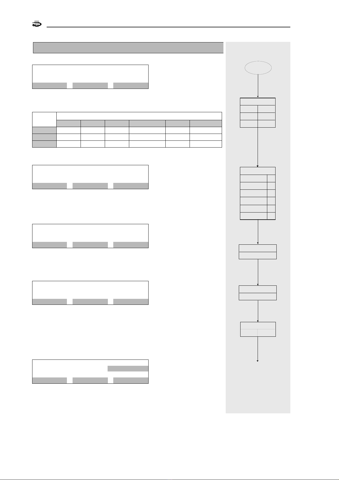
1. Reagents and limit value
Indicator type
S t e p n o . : 1 . 1
Typ: CA9
8 - 1 6 0 m g / l
▼N E X T ▲
Through different indicators, different measurement ranges can be determined.
There are 5 indicator types available. With the help of the "NEXT" key, select the
indicator used in the instrument.
Measurement rangeIndicator
type ° dH °E °F mg/LCaCO3gpg mmol/Lit.
CA 3 0.15-3.00 0.19-3.75 0.27-5.34 2.7-53.4 0.16-3.12 0.027-0.534
CA 9 0.45-9.00 0.6-11.2 0.8-16.0 8-160 0.47-9.30 0.08-1.60
CA 30 1.5-30.0 1.9-37.5 2.7-53.4 27-534 1.6-31.2 0.27-5.34
Physical unit of water hardness
S t e p n o . : 1 . 2
H a r d n e s s u n i t : m g / l
▼N E X T ▲
Using the "NEXT" key, choose the unit in which the water hardness is to be dis-
played:
°dH, °E, °F, mg/l CaCO3, gpg or mmol/ltr.
Correction factor
S t e p n o . : 1 . 3
C o r r e c t i o n f a c t o r 1 , 0 0
▼►#
Due to component tolerances it may be necessary to adjust the displayed water
hardness to the actual water hardness. You can enter a correction factor within
the range from 0.50 to 1.50 .
Limit value of the water hardness
S t e p n o . : 1 . 4
L i m . v a l u e : 9 . 0 m g / l
▲
▼►#
Determine the value of the limit at which a message is to occur when the water
hardness is over- or underrun (see programme step 1.5).
Attention: The limit value of the water hardness is dependent on the choice of
the indicator type and the water hardness. Check the limit value of the water
hardness if you have changed programme step 1.1 or 1.2. If a recorder is used,
the scale in programme step 8.2 must also be re-assessed.
Limit value monitoring
S t e p n o . : 1 . 5
L i m . v a l u e : M i n / M a x
▲
▼►▲
It can be laid down whether the signalisation of the limit monitoring occurs in
the event of an underrun = soft water (MIN) or an overrun = hard water (MAX)
of the limit value.
Example:
In monitoring an ion exchanger, the overrun is selected (MAX).
In monitoring a blending facility, the underrun (MIN) can be programmed if one wishes to monitor a minimum water
hardness.
2.1
START
1.5
CA 3
1.1
Monitoring
Min Max
CA 9
CA 30
Indicator type
1.3
Correction factor
°dH
°E
°F
mg/l CaCO
gpg
Water hardness
3
mmol/ltr
1.2
1.4
Limit value
Changing and calling up the programme data
Analysis sequence
12
SYCON
3000 C
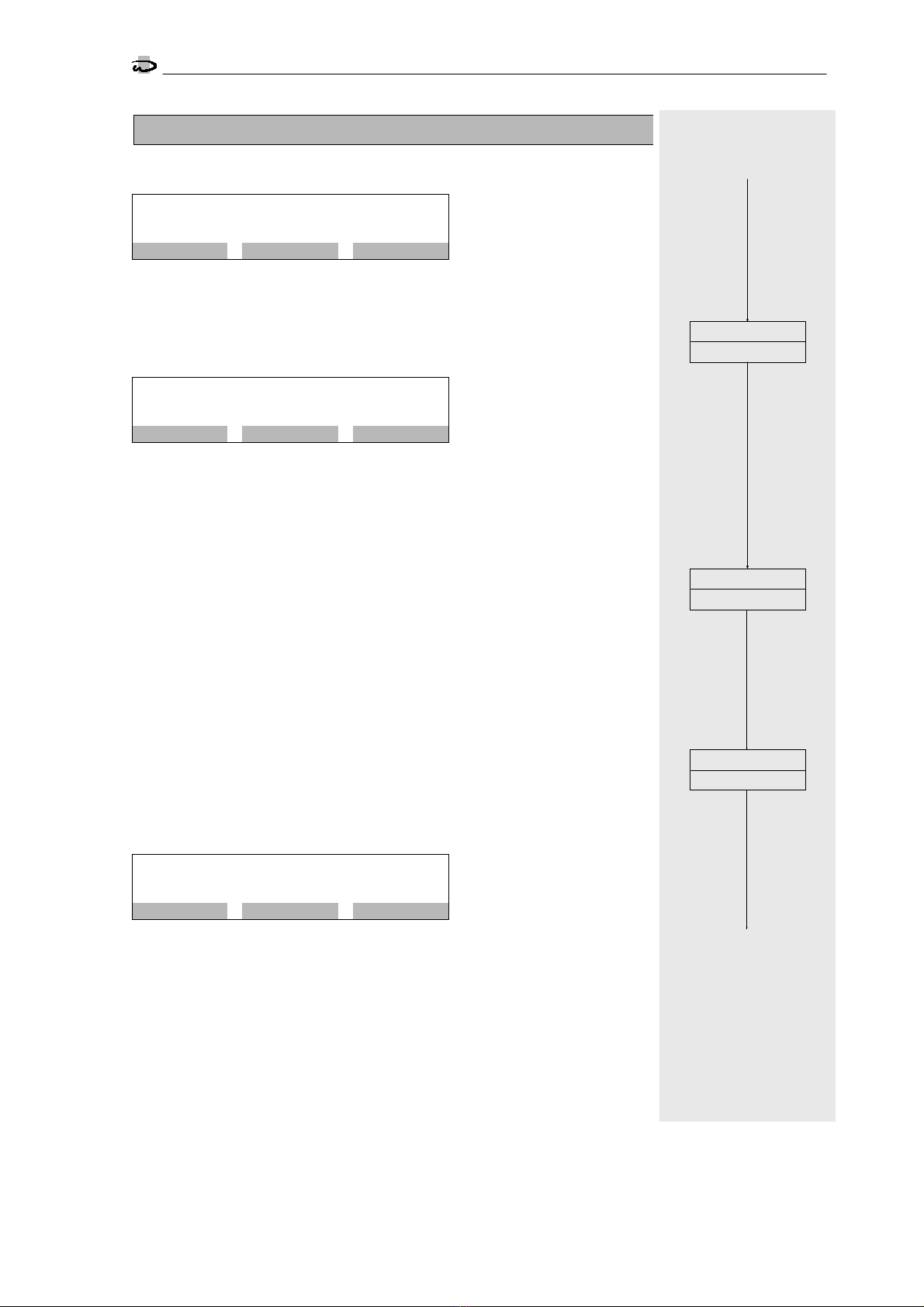
2. Analysis sequence
Flush time
S t e p n o . : 2 . 1
F l u s h t i m e 6 0 s
▲
▼►#
Prior to every extraction of a test sample, the supply line to the instrument is
flushed. Flush times from 10-999 seconds can be entered.
Analysis interval 1
S t e p n o . : 2 . 2
A n a l . i n t e r v a l 1 5 m
▲
▼►#
Analyses can be conducted at fixed intervals. Enter an Analysis interval 1 in the
range from 3 to 9'999 minutes. With the commencement of analysis, the inter-
val timing is restarted.
Attention!
The shortest time between two analyses arises from the rigidly predetermined
analytical cycle, the flush time set in programme step 1.1, the duration of titra-
tion and – insofar as it has been programmed in programme step 6.8 – from
the analysis delay entered.
A new analysis is only started if the previous one has been completed. For this
reason, an analysis interval can be greater than that programmed in this sec-
tion.
Note:
If a water meter is used, a quantity-dependent analytical sequence can also be
selected. The chronological analytical order is always active for reasons of secu-
rity.
Analyses are not automatically started, however, if the input "Analysis stop" is
active.
Analysis interval 2
S t e p n o . : 2 . 3
A n a l . i n t e r v a l 2 3 m
▲
▼►#
If the limit value is exceeded in an analysis, the interval time is redetermined with
the Analysis interval 2 taking into account the time expired. This allows the sub-
sequent analyses to be conducted at shorter time intervals after a limit value has
been exceeded.
This interval should therefore be smaller than the Analysis interval 1. Times in
the range from 3-9'999 minutes can be entered.
2.2
Analysis interval 1
1.4
m
2.1
Flush time
s
3.1
2.3
Analysis interval 2
m

Changing and calling up the programme data
Selection of the programmable input functions
13
SYCON
3000 C
3. Selection of the programmable input functions
From the 4 available input functions, maximally 2 can be programmed to the
two inputs IN1 and IN2 of the analyser. Each input function can only be used
once. In programme step 3.3, it is determined whether the inputs are active with
open or closed contact.
Parameters – such as a response delay – must still be entered for the selected
inputs in programme steps 4.1- 4.5.
A description of the inputs can be found in the chapter Input functions on page
7.
Input: IN 1
S t e p n o . : 3 . 1
S t a t S t o p R e s t W a t M e
I N P U T 1 = S t a r t A n a l y s i s
▼►▲
Select the desired input function for the input INPUT 1 (IN1) with the help of the
"►" key.
Stat = Start analysis Rest = Reset relay
Stop = Stop analysis WatMe = Water meter
Input: IN 2
S t e p n o . : 3 . 2
S t a t S t o p R e s t W a t M e
I N P U T 2 = S t o p A n a l y s i s
▼►▲
Select in accordance with programme step 3.1 the desired input function for the
input INPUT 2 (IN2) with the help of the "►" key.
Activation of the input functions
S t e p n o . : 3 . 3
S T A R T | S T O P |
▲
▼►#
Select the way the inputs are activated for the inputs selected in the programme
steps above.
Press the "►" key to select the input functions programmed for the inputs IN1
and IN2 and the "#" key to choose between "|" or "-".
"|" Activation of the selected input function when the contact is closed (NO con-
tact)
"-" Activation of the selected input function when the contact is open (NC con-
tact)
4.1
3.3
Stat Stop Rest WatMe
Input IN 2
3.2
Activatio n
Stat Stop Rest WatMe
Input IN 1
2.3
3.1

Changing and calling up the programme data
Parameters of the input funktions
14
SYCON
3000 C
4. Parameters of the input functions
In line with the selection made in programme step 3.1 and 3.2, supplementary
data must be entered in the form of parameters for the inputs IN1 and IN2.
Input function "START"
Delay time Analysis start
S t e p n o . : 4 . 1
D e l a y s t a r t : 7 s
▲
▼►#
Enter for the input function "Start" a delay time in the range of 1 to 99 sec-
onds.
Input function "STOP"
Delay time Analysis stop
S t e p n o . : 4 . 2
D e l a y s t o p : 3 s
▲
▼►#
Enter for the input "Analysis stop" a delay time in the range of 1 to 99 sec-
onds.
Input function "Reset relay"
Delay time Delete relay
S c h r i t t N r : 4 . 3
D e l a y r e l a y : 3 s
▲
▼►#
Enter for the input "Reset relay" a delay time in the range of 1 to 99 sec-
onds.
Input function "Water meter"
Water volume 1 between the analyses
S c h r i t t N r : 4 . 4
W a t e r v o l 1 1 . 0 0 c b m
▼►#
Enter the Water volume 1 after which a new analysis is to be started. You can
programme values in the range from 0.01 to 650.00 cbm.
Water volume 2 between the analyses
S t e p n o . : 4 . 5
W a t e r v o l 2 0 . 1 0 c b m
▼►#
After an overrun of the limit value, the following analysis is started in accor-
dance with Water volume 1 instead of Water volume 2. You can programme
values in the range from 0.01 to 650.00 cbm.
Pulse interval of the water meter
S t e p n o . : 4 . 6
W a t e r m e t e r 1 0 0 . 0 L / I
▼►#
Enter the pulse train of the water meter. You can enter values from 0.1 to 5'000.0 Ltr./ Imp.
5.1
Input
Delay
4.1
s
Analysis start
?
Delay
4.2
s
Pulse interval
4.6
L/I
Input
Analysis stop
?
Water volume 1
4.4
cbm
Input
Water
?
Delay
4.3
s
Input
relay
?
3.3
yes
no
yes
no
Res et
yes
no
volume
5.1
no
yes
Water volume 2
4.5
cbm

Changing and calling up the programme data
Selection of the programmable output functions
15
SYCON
3000 C
5. Selection of the programmable output functions
Of the 5 available output functions, maximally 3 can be programmed to the
outputs OUT1, OUT2 and OUT3 of the analyser. The output function "Perma-
nent signal" exists twice (PR1 and PR2). With the output function PR2, the relay
can be activated in the event of a fault as well as when the preset water hard-
ness is exceeded. In programme step 5.4 it is determined whether the outputs
are active when the electrical voltage is switched off or live.
Parameters – such as the pulse length – must also be entered for the selected
output functions in programme steps 6.1 to 6.11. A description of the outputs
can be found in the chapter Output functions on page 8.
Output: OUT 1
S t e p n o . : 5 . 1
I M P P S 1 P S 2 A N A S I G
O U T 1 = P u l s e s i g n a l
▼►▲
Choose the desired output function for the output OUT1.
Press the INFO key to display the abbreviation in plain text.
IMP = Pulse signal ANA = Analysis is running
PS1 = Permanent signal 1 SIG = Signal relay
PS2 = Permanent signal 2
Output: OUT 2
S t e p n o . : 5 . 2
I M P P S 1 P S 2 A N A S I G
O U T 2 = P e r m a n e . s i g n a l 1
▼►▲
Select according to programme step 5.1 the desired output function for the
output OUT2.
Output: OUT 3
S t e p n o . : 5 . 3
I M P P S 1 P S 2 A N A S I G
O U T 3 = S i g n a l r e l a y
▼►▲
Select the desired output function for the output OUT3 in accordance with pro-
gramme step 5.1.
Activation of the output function
S t e p n o . : 5 . 4
I M P | P S 1 | S I G
-
▲
▼►#
Select the activation of the output functions for the outputs selected in pro-
gramme steps 5.1 to 5.3.
"-" Activation of the selected output function with relay inoperative (dropped-
out)
"|" Activation of the selected output function with relay operative (pulled-in).
General note:
In deciding whether e.g. a valve is active when live i.e. open or not, one considers the reaction of
the treatment plant in a current-free state. In such a case no undesired functions should occur in the
plant.
Example flush valve: When the analyser is switched off, a rinse valve must not be open, even if it is
triggered by an external supply voltage.
Choose a flush valve that opens when carrying voltage and programme "|".
Example fault message: When the analyser has no electrical power, a fault message should occur. Programme "-".
6.1
4.*
5.4
5.2
5.3
IMP
Output: OUT 1
PS1 PS2 ANA SIG
5.1
Activation
IMP
Output: OUT 2
PS1 PS2 ANA SIG
IMP
Output: OUT 3
PS1 PS2 ANA SIG

Changing and calling up the programme data
Parameters of the output functions
16
SYCON
3000 C
6. Parameters of the output functions
In line with the selection made in programme steps 5.1 to 5.3, supplementary
data must be entered in the form of parameters for the outputs OUT 1 to OUT
3.
Output function: Pulse signal
Pulse length
S t e p n o . : 6 . 1
P u l s e l e n g h t 1 0 s
▲
▼►#
The length of the pulse signal can be laid down within the range from 1 to 999
seconds.
Number of bad messages
S t e p n o . : 6 . 2
N u m b e r m e s s a g e s 1 *
▼#▲
You can programme the number of bad messages after which the output func-
tion pulse signal is activated. Values from 1 to 5 can be entered. With a value
greater than 1, when the next analysis occurs is programmed in programme
step 6.10 or 6.11.
Note:
The pulse output is always activated as soon as a bad message is displayed after an analysis and
the number of successive bad messages is the same as or greater than the value entered in pro-
gramme step 6.2 .
In programme step 1.5, it is determined whether a bad message is to occur if the limit value is over-
run or underrun.
Attention!
If the output function "Permanent signal 1" or "Permanent signal 2" is so programmed that the ana-
lyser performs no more analyses before the value entered in programme step 6.2 is reached, no
further signal can be emitted.
Output function: Permanent signal 1
Activation only with a limit overrun or underrun
Automatic delete function 1
S t e p n o . : 6 . 3
A u t o m a t . d e l e t e 1 Y / N
▲
▼►▲
You can programme whether further analyses are carried out after the activa-
tion of the output function Permanent signal 1. If further analyses are con-
ducted, the relevant relay is automatically deactivated again if the result "Water
good" occurs in one of the next analyses.
If no further analyses are conducted, the relay must be deleted by hand or via
the input "Delete relay". Moreover, an analysis must be restarted.
Automatic deletion Yes: Consecutive analyses even after a bad message
Automatic deletion No: Analysis stop in the event of a bad mesaage
Number of the bad messages
S t e p n o . : 6 . 4
N u m b e r m e s s a g e s 2 *
▼#▲
You can programme the number of bad messages (limit overruns/underruns)
after which the output function is activated. Values from 1 to 5 can be entered.
With a value greater than 1, it is laid down in programme step 6.9 or 6.10
when the next analysis occurs.
6.5
Output
Pulse lenght
6.1
s
Pulse signal
?
Autom.delete1
6.4
Output
Permanent
signal 1
6.3
5.4
no
yes
no
?
yes
Yes No
Bad messages
6.2
*
6.5
Bad messages
*
Table of contents
Other RLS Wacon Measuring Instrument manuals


